EP1237443B1 - Dispositif destine a monter une equerre sur un montant vertical - Google Patents
Dispositif destine a monter une equerre sur un montant vertical Download PDFInfo
- Publication number
- EP1237443B1 EP1237443B1 EP00987874A EP00987874A EP1237443B1 EP 1237443 B1 EP1237443 B1 EP 1237443B1 EP 00987874 A EP00987874 A EP 00987874A EP 00987874 A EP00987874 A EP 00987874A EP 1237443 B1 EP1237443 B1 EP 1237443B1
- Authority
- EP
- European Patent Office
- Prior art keywords
- fitting
- apertures
- engaging members
- adapter
- bracket
- Prior art date
- Legal status (The legal status is an assumption and is not a legal conclusion. Google has not performed a legal analysis and makes no representation as to the accuracy of the status listed.)
- Expired - Lifetime
Links
- 238000007373 indentation Methods 0.000 claims description 8
- 125000006850 spacer group Chemical group 0.000 claims description 5
- 230000003993 interaction Effects 0.000 claims 1
- 230000015572 biosynthetic process Effects 0.000 description 3
- 238000005755 formation reaction Methods 0.000 description 3
- 239000000470 constituent Substances 0.000 description 1
- 238000000034 method Methods 0.000 description 1
Images

Classifications
-
- A—HUMAN NECESSITIES
- A47—FURNITURE; DOMESTIC ARTICLES OR APPLIANCES; COFFEE MILLS; SPICE MILLS; SUCTION CLEANERS IN GENERAL
- A47B—TABLES; DESKS; OFFICE FURNITURE; CABINETS; DRAWERS; GENERAL DETAILS OF FURNITURE
- A47B57/00—Cabinets, racks or shelf units, characterised by features for adjusting shelves or partitions
- A47B57/30—Cabinets, racks or shelf units, characterised by features for adjusting shelves or partitions with means for adjusting the height of detachable shelf supports
- A47B57/40—Cabinets, racks or shelf units, characterised by features for adjusting shelves or partitions with means for adjusting the height of detachable shelf supports consisting of hooks coacting with openings
- A47B57/42—Cabinets, racks or shelf units, characterised by features for adjusting shelves or partitions with means for adjusting the height of detachable shelf supports consisting of hooks coacting with openings the shelf supports being cantilever brackets
Definitions
- the present invention relates to a device for fitting a load-bearing bracket for a shelf or the like, for example, to an upright support provided with at least one vertical row of spaced fitting apertures, the device comprising a fitting member for fitting the adapter to the upright support.
- Brackets of this type are generally used in pairs with an intervening shelf plane in order to form a shelf that can easily be fitted to two upright supports, see e.g. US-A-4 684 094.
- the interval between the fitting apertures in the upright is furthermore relatively large, which means that the shelves cannot be finely adjusted for height. In many instances this means that optimum use cannot be made of valuable space for goods in a shop, for example.
- An object of the present invention is to produce a device, which enables a bracket of a particular make to be fitted to an upright support of another make without the need for the entire bracket to be specially manufactured in order to fit precisely the upright support in question.
- Another object is to produce a device for fitting load-bearing brackets to upright supports, which will permit a greater degree of fine height adjustment than that corresponding to the interval between the fitting holes in the upright support.
- the invention is based on the insight that the aforementioned objects can be achieved by means of an adapter and a fitting member, of which only the fitting member needs to be adjusted depending on the upright support in question.
- the special characteristic of a device of the type specified in the introductory part is that the end of the bracket facing the upright support is provided with an adapter, that the said fitting member is designed with opposing pairs of engaging members separated in the vertical direction, that the edge surface of the adapter facing the upright support has a vertical row of spaced fitting apertures, that the interval between pairs of the said apertures is equal to the distance between the one pair of engaging members on the said fitting member, and that the distance between the second pair of engaging members on the said fitting member is equal to the interval between pairs of fitting apertures in the upright support.
- This device allows a shelf manufacturer to use the same bracket for fitting a shelf to different upright supports by using a single fitting member adapted to the upright in question.
- the distance between two shelf planes situated one above the other can be finely adjusted essentially to the precise distance required in each case.
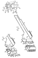
- 1 denotes the end of a load-bearing bracket facing an upright support 2.
- the bracket shown is intended to be connected to a similar bracket running parallel in order to support a shelf.
- the brackets are connected by means of a transverse plate (not shown), the ends of which are brought down into a slot 3 in a flange 4 running along each bracket.
- the flange 4 may then serve as bearing surface for a shelf plane.
- a shelf plane formed from bars can be fitted to the brackets by introducing the ends of the said bars in through holes 5 in the brackets.
- the shelf may be of the type, for example, described in our Swedish patent application No. 9903198-1, which has an extendable shelf plane.
- the end section of the bracket 1 is designed with two projecting engaging members 6, 7.
- the latter are intended to interact with an adapter 8, which is made up of two side plates 9 and an intermediate spacer plate 10.
- the spacer plate 10 is designed with indentations 11 along two opposite edges, the said indentations together with the side plates 9 forming a vertical row of fitting apertures 12 along two opposite edge surfaces of the adapter 8.
- One row of the said apertures is intended to interact with the engaging members 6 and 7 on the bracket 1, whilst the second row of engagement apertures 12 is intended to interact with engaging members 13, 14, which project in one direction from a plate-shaped fitting member 15.
- the adapter 8 is provided with a number, suitably at least three pairs, of fitting apertures 12 with spacing interval equal to the distance between the engaging members 6 and 7 of the bracket 1. It likewise contains a number of apertures 12, suitably at least two pairs, with a spacing interval equal to the distance between the engaging members 13 and 14 on the fitting member 15.
- At least the upper engaging members 6 and 13 are each made with a notch formation 19 and 20 respectively, which are designed to be capable of interlocking with corresponding notch formations 21 and 22 respectively in indentations in the spacer plate 10 in the adapter 8.
- the procedure is as follows. First an adapter 8 is fitted at a suitable height on engaging members 6 and 7 of the bracket 1. This can be done by means of a pivoting movement, as illustrated in Figure 3. A fitting member 15 is then fitted at a suitable height on the adapter 8, likewise by means of a pivoting movement. The bracket 1 with its adapter 8 and fitting member 15 is then fitted at the desired height to the upright support 1 with the aid of the engaging members 16 and 17, see Figure 3. In their bottom edges there are indentations 23, 24, which permit a certain angular adjustment in the horizontal plane of the bracket 1. Fitting may, of course, also be done in a different order.
- the device described provides great scope for fine adjustment of the height of the bracket, since the fitting member 15 can be fitted both at different heights on the upright 1, and at different heights on the adapter 8.
- the bracket 1 can also be fitted at different heights on the adapter 8. The height of a shelf can also be easily adjusted later.
- Figure 4 shows a simplified design of a device according to the invention, in which the adapter 8 is fastened to the end of a bracket 1.
- the end of the bracket may be designed in the form of an adapter with fitting apertures 12.
- the bracket is provided with a fitting device for an extendable shelf, which device does not constitute any part of the present invention and will consequently not be described here.
- one engaging member 13 on the fitting part is designed with an upward-facing notch formation 25 in order to improve the engagement in the adapter 8.
- a shelf manufacturer can use a standard bracket for all shelves by providing it with a loose or fixed adapter 8 and a fitting member 15. It is therefore only the distance between the engaging members 16 and 17 of the fitting member 15 that needs to be specially adapted to the respective upright support.
- Other parts of the device can be manufactured in one design, which means longer production runs and hence lower costs. Use of a device according to the invention also facilitates stock-keeping and fitting.
Landscapes
- Assembled Shelves (AREA)
- Display Racks (AREA)
- Spinning Or Twisting Of Yarns (AREA)
- Furniture Connections (AREA)
- Rolls And Other Rotary Bodies (AREA)
- Motor Or Generator Frames (AREA)
- Vehicle Step Arrangements And Article Storage (AREA)
- Rear-View Mirror Devices That Are Mounted On The Exterior Of The Vehicle (AREA)
- Forklifts And Lifting Vehicles (AREA)
Claims (10)
- Dispositif destiné à assembler une équerre de support de charge, par exemple, pour une étagère ou analogue, sur un montant vertical (2) comportant au moins une rangée verticale d'ouvertures de montage espacées (18), l'extrémité de l'équerre (1) étant orientée face au montant vertical (2), comporte un adaptateur (8), le dispositif comprend un élément de montage (15) afin d'assembler l'adaptateur sur le montant vertical (2), caractérisé en ce que ledit élément de montage (15) est conçu avec des paires opposées d'éléments de couplage (13, 14 ; 16, 17) séparés dans la direction verticale, en ce que la surface de bord de l'adaptateur (8) orientée face au montant vertical (2) présente une rangée verticale d'ouvertures de montage espacées (12), en ce que l'intervalle entre des paires desdites ouvertures est égal à la distance séparant la première paire d'éléments de couplage (13, 14) sur ledit élément de montage (15), et en ce que la distance séparant l'autre paire d'éléments de couplage (16, 17) sur ledit élément de montage (15) est égale à l'intervalle compris entre des paires d'ouvertures de montage (18) sur le montant vertical (2).
- Dispositif selon la revendication 1, caractérisé en ce que l'adaptateur (8) est fixé sur l'équerre (1) et présente au moins deux paires d'ouvertures de montage (12) afin de coopérer avec les éléments de couplage (13, 14) sur l'élément de montage (15).
- Dispositif selon la revendication 1 ou 2, caractérisé en ce que l'adaptateur (8) comprend deux plaques latérales sensiblement rectangulaires (9) et une entretoise en forme de plaque intermédiaire (10), et en ce que l'entretoise est conçue avec des entailles (11) sur un bord latéral qui, ensemble avec les plaques latérales (9), forment lesdites ouvertures de montage (12).
- Dispositif selon la revendication 3, caractérisé en ce qu'au moins l'une desdites entailles (11) dans chaque paire d'ouvertures de montage (12) est conçue avec un élément formant encoche (22) qui coopère avec un élément formant encoche correspondant (20) sur l'un des éléments de couplage (13) de l'élément de montage (15).
- Dispositif selon la revendication 4, caractérisé en ce que l'ouverture de montage supérieure (12) de chaque paire d'ouvertures comporte un élément formant encoche (22) sur son bord inférieur avant.
- Dispositif selon l'une quelconque des revendications 1 à 5, destiné à assembler une équerre de support de charge, par exemple, pour une étagère ou analogue sur un montant vertical, l'équerre (1), à son extrémité face au montant (2), comportant deux éléments de couplage (6, 7) verticalement séparés, caractérisé en ce qu'il comprend un adaptateur (8) qui peut être monté sur l'équerre (1), en ce que deux surfaces de bord opposées de l'adaptateur (8) comportent chacune une rangée verticale d'ouvertures de montage espacées (12), en ce que l'intervalle entre des paires d'ouvertures sur une première surface de bord de l'adaptateur (8) est égal à la distance entre des éléments de couplage (6, 7) de l'équerre (1), en ce que l'intervalle entre des paires d'ouvertures (12) sur l'autre surface de bord de l'adaptateur (8) est égal à la distance séparant la première paire d'éléments de couplage (13, 14) sur ledit élément de montage (15), et en ce que la distance séparant la seconde paire d'éléments de couplage (16, 17) sur ledit élément de montage est égale à l'intervalle entre des paires d'ouvertures de montage (18) sur le montant vertical (2).
- Dispositif selon la revendication 6, caractérisé en ce que l'adaptateur (8) comporte au moins trois paires d'ouvertures de montage (12) afin de coopérer avec les éléments de couplage (6, 7) sur l'équerre (1) et au moins deux paires d'ouvertures de montage (12) afin de coopérer avec les éléments de couplage (13, 14) sur l'élément de montage (15).
- Dispositif selon l'une quelconque des revendications 1 à 7, caractérisé en ce que les éléments de couplage (16, 17) de l'élément de montage (15) destinés à coopérer avec les ouvertures de montage (18) sur le montant vertical (2) sont conçus avec des entailles (23, 24) sur leur surface de bord inférieur de manière à recevoir une paroi de définition inférieure de chaque ouverture de montage (18).
- Dispositif selon la revendication 8, caractérisé en ce que chacun desdits éléments de couplage (16, 17) comportent au moins deux entailles (23, 24) afin de permettre le réglage de l'angle d'inclinaison de l'équerre (1).
- Etagère supportée par une équerre le long de chaque côté, caractérisée en ce que chaque équerre (1) est montée sur un montant vertical (2) associé, au moyen d'un dispositif (8, 15) selon l'une quelconque des revendications 1 à 9.
Applications Claiming Priority (5)
| Application Number | Priority Date | Filing Date | Title |
|---|---|---|---|
| SE9904545 | 1999-12-13 | ||
| SE9904545A SE516331C2 (sv) | 1999-12-13 | 1999-12-13 | Anordning för montering av en lastbärande konsol samt hylla uppburen av en konsol monterad medelst en sådan anordning |
| SE0003001 | 2000-08-24 | ||
| SE0003001A SE517489C2 (sv) | 1999-12-13 | 2000-08-24 | Anordning för montering av en lastbärande konsol på en stativstolpe samt hylla uppburen av konsoler monterade med dylika anordningar |
| PCT/SE2000/002472 WO2001045535A1 (fr) | 1999-12-13 | 2000-12-08 | Dispositif destine a monter une equerre sur un montant vertical |
Publications (2)
| Publication Number | Publication Date |
|---|---|
| EP1237443A1 EP1237443A1 (fr) | 2002-09-11 |
| EP1237443B1 true EP1237443B1 (fr) | 2004-10-13 |
Family
ID=26655218
Family Applications (1)
| Application Number | Title | Priority Date | Filing Date |
|---|---|---|---|
| EP00987874A Expired - Lifetime EP1237443B1 (fr) | 1999-12-13 | 2000-12-08 | Dispositif destine a monter une equerre sur un montant vertical |
Country Status (7)
| Country | Link |
|---|---|
| US (1) | US20020179797A1 (fr) |
| EP (1) | EP1237443B1 (fr) |
| AT (1) | ATE279134T1 (fr) |
| AU (1) | AU2414901A (fr) |
| DE (1) | DE60014963T2 (fr) |
| SE (1) | SE517489C2 (fr) |
| WO (1) | WO2001045535A1 (fr) |
Families Citing this family (4)
| Publication number | Priority date | Publication date | Assignee | Title |
|---|---|---|---|---|
| US6959021B2 (en) * | 2001-02-07 | 2005-10-25 | Ocg Technology Licensing, Llc | Raman fiber laser |
| US7322483B2 (en) * | 2005-08-31 | 2008-01-29 | Suncast Corporation | Cantilever shelving for utility shed |
| WO2010009298A2 (fr) * | 2008-07-16 | 2010-01-21 | Nucor Corporation | Système et appareil porteur de charge |
| US9456692B2 (en) * | 2014-10-09 | 2016-10-04 | Knape & Vogt Manufacturing Company | Multi-piece shelf brackets and methods of assembling the same |
Family Cites Families (3)
| Publication number | Priority date | Publication date | Assignee | Title |
|---|---|---|---|---|
| US3353684A (en) * | 1965-10-22 | 1967-11-21 | Chesley Ind Inc | Shelf structure |
| US4684094A (en) * | 1984-09-10 | 1987-08-04 | Tusco Manufacturing Co. | Adjustable bracket assembly |
| US5535972A (en) * | 1994-12-28 | 1996-07-16 | Fallago; Richard P. | Adapter for adjustable shelving system |
-
2000
- 2000-08-24 SE SE0003001A patent/SE517489C2/sv not_active IP Right Cessation
- 2000-12-08 DE DE60014963T patent/DE60014963T2/de not_active Expired - Fee Related
- 2000-12-08 EP EP00987874A patent/EP1237443B1/fr not_active Expired - Lifetime
- 2000-12-08 AT AT00987874T patent/ATE279134T1/de not_active IP Right Cessation
- 2000-12-08 US US10/148,834 patent/US20020179797A1/en not_active Abandoned
- 2000-12-08 WO PCT/SE2000/002472 patent/WO2001045535A1/fr not_active Ceased
- 2000-12-08 AU AU24149/01A patent/AU2414901A/en not_active Abandoned
Also Published As
| Publication number | Publication date |
|---|---|
| SE517489C2 (sv) | 2002-06-11 |
| AU2414901A (en) | 2001-07-03 |
| DE60014963D1 (de) | 2004-11-18 |
| DE60014963T2 (de) | 2006-03-09 |
| ATE279134T1 (de) | 2004-10-15 |
| SE0003001D0 (sv) | 2000-08-24 |
| SE0003001L (sv) | 2001-06-14 |
| EP1237443A1 (fr) | 2002-09-11 |
| US20020179797A1 (en) | 2002-12-05 |
| WO2001045535A1 (fr) | 2001-06-28 |
Similar Documents
| Publication | Publication Date | Title |
|---|---|---|
| US4493425A (en) | Rack assembly apparatus | |
| US6684929B2 (en) | Panel system | |
| US4405052A (en) | Shelf support bracket | |
| US4205815A (en) | Shelf bracket, shelf bracket-stud combination and shelf bracket-clip combination | |
| US5412912A (en) | Modular slatwall assembly | |
| US4821649A (en) | Sheet metal shelving | |
| US4189123A (en) | Locking modular assembly | |
| US6349911B1 (en) | Workplace apparatus including mounting bracket | |
| US5595127A (en) | Shelving system | |
| US20050056749A1 (en) | Attachment bracket for shelf support system | |
| EP1237443B1 (fr) | Dispositif destine a monter une equerre sur un montant vertical | |
| US3160281A (en) | Partition structure | |
| US4334571A (en) | Screen and shelving system | |
| US3624780A (en) | Floor and ceiling mounting for rack and shelving system | |
| US4394809A (en) | Coreless hung panel assembly | |
| US3978631A (en) | Display units with socket-mounted standards | |
| EP0129626A1 (fr) | Dispositif et méthode pour suspendre des placards ou similaires | |
| US4884854A (en) | Interconnecting panels for knockdown structures | |
| US6227507B1 (en) | Closet shelving system | |
| EP0477125B1 (fr) | Système d'étagères sous forme de boîtes | |
| JPS62111071A (ja) | ユニツトル−ムにおける側パネルの立設構造及び立設方法 | |
| US6314702B1 (en) | Assembled frame structure | |
| GB2148445A (en) | Rack assembly | |
| GB2205378A (en) | Clip for shelving system | |
| EP0442750A1 (fr) | Panneau d'affichage ou de revêtement |
Legal Events
| Date | Code | Title | Description |
|---|---|---|---|
| PUAI | Public reference made under article 153(3) epc to a published international application that has entered the european phase |
Free format text: ORIGINAL CODE: 0009012 |
|
| 17P | Request for examination filed |
Effective date: 20020425 |
|
| AK | Designated contracting states |
Kind code of ref document: A1 Designated state(s): AT BE CH CY DE DK ES FI FR GB GR IE IT LI LU MC NL PT SE TR |
|
| AX | Request for extension of the european patent |
Free format text: AL;LT PAYMENT 20020425;LV PAYMENT 20020425;MK;RO PAYMENT 20020425;SI PAYMENT 20020425 |
|
| GRAP | Despatch of communication of intention to grant a patent |
Free format text: ORIGINAL CODE: EPIDOSNIGR1 |
|
| GRAS | Grant fee paid |
Free format text: ORIGINAL CODE: EPIDOSNIGR3 |
|
| GRAA | (expected) grant |
Free format text: ORIGINAL CODE: 0009210 |
|
| AK | Designated contracting states |
Kind code of ref document: B1 Designated state(s): AT BE CH CY DE DK ES FI FR GB GR IE IT LI LU MC NL PT SE TR |
|
| AX | Request for extension of the european patent |
Extension state: LT LV RO SI |
|
| PG25 | Lapsed in a contracting state [announced via postgrant information from national office to epo] |
Ref country code: IT Free format text: LAPSE BECAUSE OF FAILURE TO SUBMIT A TRANSLATION OF THE DESCRIPTION OR TO PAY THE FEE WITHIN THE PRE;WARNING: LAPSES OF ITALIAN PATENTS WITH EFFECTIVE DATE BEFORE 2007 MAY HAVE OCCURRED AT ANY TIME BEFORE 2007. THE CORRECT EFFECTIVE DATE MAY BE DIFFERENT FROM THE ONE RECORDED.SCRIBED TIME-LIMIT Effective date: 20041013 Ref country code: LI Free format text: LAPSE BECAUSE OF FAILURE TO SUBMIT A TRANSLATION OF THE DESCRIPTION OR TO PAY THE FEE WITHIN THE PRESCRIBED TIME-LIMIT Effective date: 20041013 Ref country code: BE Free format text: LAPSE BECAUSE OF FAILURE TO SUBMIT A TRANSLATION OF THE DESCRIPTION OR TO PAY THE FEE WITHIN THE PRESCRIBED TIME-LIMIT Effective date: 20041013 Ref country code: NL Free format text: LAPSE BECAUSE OF FAILURE TO SUBMIT A TRANSLATION OF THE DESCRIPTION OR TO PAY THE FEE WITHIN THE PRESCRIBED TIME-LIMIT Effective date: 20041013 Ref country code: TR Free format text: LAPSE BECAUSE OF FAILURE TO SUBMIT A TRANSLATION OF THE DESCRIPTION OR TO PAY THE FEE WITHIN THE PRESCRIBED TIME-LIMIT Effective date: 20041013 Ref country code: FI Free format text: LAPSE BECAUSE OF FAILURE TO SUBMIT A TRANSLATION OF THE DESCRIPTION OR TO PAY THE FEE WITHIN THE PRESCRIBED TIME-LIMIT Effective date: 20041013 Ref country code: AT Free format text: LAPSE BECAUSE OF FAILURE TO SUBMIT A TRANSLATION OF THE DESCRIPTION OR TO PAY THE FEE WITHIN THE PRESCRIBED TIME-LIMIT Effective date: 20041013 Ref country code: CH Free format text: LAPSE BECAUSE OF FAILURE TO SUBMIT A TRANSLATION OF THE DESCRIPTION OR TO PAY THE FEE WITHIN THE PRESCRIBED TIME-LIMIT Effective date: 20041013 Ref country code: SE Free format text: LAPSE BECAUSE OF FAILURE TO SUBMIT A TRANSLATION OF THE DESCRIPTION OR TO PAY THE FEE WITHIN THE PRESCRIBED TIME-LIMIT Effective date: 20041013 Ref country code: CY Free format text: LAPSE BECAUSE OF FAILURE TO SUBMIT A TRANSLATION OF THE DESCRIPTION OR TO PAY THE FEE WITHIN THE PRESCRIBED TIME-LIMIT Effective date: 20041013 |
|
| REG | Reference to a national code |
Ref country code: GB Ref legal event code: FG4D |
|
| REG | Reference to a national code |
Ref country code: CH Ref legal event code: EP |
|
| REG | Reference to a national code |
Ref country code: IE Ref legal event code: FG4D |
|
| REF | Corresponds to: |
Ref document number: 60014963 Country of ref document: DE Date of ref document: 20041118 Kind code of ref document: P |
|
| PG25 | Lapsed in a contracting state [announced via postgrant information from national office to epo] |
Ref country code: LU Free format text: LAPSE BECAUSE OF NON-PAYMENT OF DUE FEES Effective date: 20041208 Ref country code: IE Free format text: LAPSE BECAUSE OF NON-PAYMENT OF DUE FEES Effective date: 20041208 |
|
| PG25 | Lapsed in a contracting state [announced via postgrant information from national office to epo] |
Ref country code: MC Free format text: LAPSE BECAUSE OF NON-PAYMENT OF DUE FEES Effective date: 20041231 |
|
| PG25 | Lapsed in a contracting state [announced via postgrant information from national office to epo] |
Ref country code: DK Free format text: LAPSE BECAUSE OF FAILURE TO SUBMIT A TRANSLATION OF THE DESCRIPTION OR TO PAY THE FEE WITHIN THE PRESCRIBED TIME-LIMIT Effective date: 20050113 Ref country code: GR Free format text: LAPSE BECAUSE OF FAILURE TO SUBMIT A TRANSLATION OF THE DESCRIPTION OR TO PAY THE FEE WITHIN THE PRESCRIBED TIME-LIMIT Effective date: 20050113 |
|
| PG25 | Lapsed in a contracting state [announced via postgrant information from national office to epo] |
Ref country code: ES Free format text: LAPSE BECAUSE OF FAILURE TO SUBMIT A TRANSLATION OF THE DESCRIPTION OR TO PAY THE FEE WITHIN THE PRESCRIBED TIME-LIMIT Effective date: 20050124 |
|
| LTIE | Lt: invalidation of european patent or patent extension |
Effective date: 20041013 |
|
| NLV1 | Nl: lapsed or annulled due to failure to fulfill the requirements of art. 29p and 29m of the patents act | ||
| REG | Reference to a national code |
Ref country code: CH Ref legal event code: PL |
|
| ET | Fr: translation filed | ||
| PLBE | No opposition filed within time limit |
Free format text: ORIGINAL CODE: 0009261 |
|
| STAA | Information on the status of an ep patent application or granted ep patent |
Free format text: STATUS: NO OPPOSITION FILED WITHIN TIME LIMIT |
|
| REG | Reference to a national code |
Ref country code: IE Ref legal event code: MM4A |
|
| 26N | No opposition filed |
Effective date: 20050714 |
|
| PGFP | Annual fee paid to national office [announced via postgrant information from national office to epo] |
Ref country code: GB Payment date: 20051121 Year of fee payment: 6 |
|
| PGFP | Annual fee paid to national office [announced via postgrant information from national office to epo] |
Ref country code: FR Payment date: 20051130 Year of fee payment: 6 |
|
| PGFP | Annual fee paid to national office [announced via postgrant information from national office to epo] |
Ref country code: DE Payment date: 20051223 Year of fee payment: 6 |
|
| PG25 | Lapsed in a contracting state [announced via postgrant information from national office to epo] |
Ref country code: DE Free format text: LAPSE BECAUSE OF NON-PAYMENT OF DUE FEES Effective date: 20070703 |
|
| GBPC | Gb: european patent ceased through non-payment of renewal fee |
Effective date: 20061208 |
|
| REG | Reference to a national code |
Ref country code: FR Ref legal event code: ST Effective date: 20070831 |
|
| PG25 | Lapsed in a contracting state [announced via postgrant information from national office to epo] |
Ref country code: GB Free format text: LAPSE BECAUSE OF NON-PAYMENT OF DUE FEES Effective date: 20061208 |
|
| PG25 | Lapsed in a contracting state [announced via postgrant information from national office to epo] |
Ref country code: PT Free format text: LAPSE BECAUSE OF NON-PAYMENT OF DUE FEES Effective date: 20050313 |
|
| PG25 | Lapsed in a contracting state [announced via postgrant information from national office to epo] |
Ref country code: FR Free format text: LAPSE BECAUSE OF NON-PAYMENT OF DUE FEES Effective date: 20070102 |