EP1237298A1 - Relaissystem mit Funktion zum Unterdrücken von Schwingungen sowie einer automatischen Abschaltfunktion des Ausgangsfür Nichtteilnehmer und ein dazugehöriges Regelverfahren - Google Patents
Relaissystem mit Funktion zum Unterdrücken von Schwingungen sowie einer automatischen Abschaltfunktion des Ausgangsfür Nichtteilnehmer und ein dazugehöriges Regelverfahren Download PDFInfo
- Publication number
- EP1237298A1 EP1237298A1 EP01104878A EP01104878A EP1237298A1 EP 1237298 A1 EP1237298 A1 EP 1237298A1 EP 01104878 A EP01104878 A EP 01104878A EP 01104878 A EP01104878 A EP 01104878A EP 1237298 A1 EP1237298 A1 EP 1237298A1
- Authority
- EP
- European Patent Office
- Prior art keywords
- signal
- output
- receiver
- repeater system
- power
- Prior art date
- Legal status (The legal status is an assumption and is not a legal conclusion. Google has not performed a legal analysis and makes no representation as to the accuracy of the status listed.)
- Granted
Links
Images


Classifications
-
- H—ELECTRICITY
- H04—ELECTRIC COMMUNICATION TECHNIQUE
- H04B—TRANSMISSION
- H04B7/00—Radio transmission systems, i.e. using radiation field
- H04B7/14—Relay systems
- H04B7/15—Active relay systems
- H04B7/155—Ground-based stations
- H04B7/15528—Control of operation parameters of a relay station to exploit the physical medium
- H04B7/15535—Control of relay amplifier gain
-
- H—ELECTRICITY
- H04—ELECTRIC COMMUNICATION TECHNIQUE
- H04B—TRANSMISSION
- H04B7/00—Radio transmission systems, i.e. using radiation field
- H04B7/14—Relay systems
- H04B7/15—Active relay systems
- H04B7/155—Ground-based stations
- H04B7/15564—Relay station antennae loop interference reduction
Definitions
- the present invention relates to a repeater system having an oscillation preventing function and a control method thereof. More specifically, the present invention relates to a repeater system interlocked with a base station transceiver system of a mobile communication system, and a control method thereof.
- a mobile communication system includes a base station transceiver system, a base station controller, a mobile switching center, and a mobile station.
- the base station transceiver system is in communications with mobile stations in a predetermined frequency band, each mobile station having a predetermined service radius.
- a plurality of base station transceiver systems are properly arranged so that the service radii of the individual base station transceiver systems are overlapped, in order to extend the service area.
- non-service areas including underground areas of a large building, interior space of a high-rise building.
- the repeater systems may have self-oscillations depending on the installation place or according to circumstances.
- the forward oscillation causes no more than a failure of connection to the corresponding service area, but the reverse oscillation results in serious defects in a reception path of the base station transceiver system connected to the repeater systems.
- a repeater system comprising: a transmitter for amplifying data received from an external base station transceiver system, converting the amplified data to a service frequency, and sending the service frequency to a mobile station in a corresponding service area; a receiver for amplifying the signal received from the mobile station and outputting the amplified signal to the base station transceiver system; and a controller for detecting the power level of the receiver, and preventing the output signal of the receiver being sent to the base station transceiver system when the power level is above a first reference value during a first time or below a second reference value during a second time.
- a method for controlling a repeater system comprising the steps of: discriminating between an oscillation signal of the repeater system, and a talking signal and an access signal, disabling a reverse output of the repeater system during oscillation of the repeater system, and after an elapse of a first time, detecting the state of power of the reverse output; disabling the reverse output of the repeater system when the power is in an oscillation state; and enabling the reverse output of the repeater system when the power not in the oscillation state and the reverse output is an access or talking signal.
- PCS personal communication service
- FIG. 1 is a schematic block diagram of a repeater system in accordance with an embodiment of the present invention.
- the repeater system includes: a first duplexer 400 for transmitting data from an external base station transceiver system on a corresponding path; a transmitter 100 for amplifying a signal received from the first duplexer 400 into a service frequency; a second duplexer 600 for transmitting the output signal of the transmitter 100 to a mobile station located in a corresponding service area in a wireless manner, and receiving a signal from the mobile station; a receiver 500 for amplifying the signal received from the second duplexer 600; and a controller 200 coupled to the output signal of the receiver 500 for detecting the power level of the receiver 500, the controller 200 preventing the output of the receiver 500 being sent to the first duplexer 400 when the detected power level is above a first reference value during a first time period or below a second reference value during a second time period.
- FIG. 2 is a detailed diagram of the controller 200 shown in FIG. 1.
- the controller 200 includes: a high level detector 220 coupled to the output of the receiver 500 for detecting a high power level of the receiver 500; a low level detector 230 coupled to the output of the receiver 500 for detecting a low power level of the receiver 500; an integrated circuit 210 for generating a control signal to prevent the output of the receiver 500 being sent to the first duplexer when the power level detected by the high level detector 220 is above the first reference value during the first time period, or when the power level detected by the low level detector 230 is below the second reference value during the second time period; and a switch SW1 for enabling or disabling transmission of the output signal of the receiver 500 to the first duplexer 400 based on the control signal of the integrated circuit 210.
- the transmitter 100 includes: a first mixer 110 for converting a signal having a high frequency received from the first duplexer 400 to a signal having an intermediate frequency; a first surface acoustic wave (SAW) filter 120 for filtering the output signal of the first mixer 110 and outputting a desired signal having an intermediate frequency; a second mixer 130 for modulating the output signal of the first SAW filter 120 to a signal having a high frequency; and a first power amplifier 140 for amplifying the output signal of the second mixer 130 and outputting the amplified signal to the second duplexer 600.
- SAW surface acoustic wave
- the receiver 500 includes: a low-noise amplifier 550 for amplifying the signal having a high frequency received from the second duplexer 600; a third mixer 540 for modulating the output signal of the low-noise amplifier 550 into a signal having an intermediate frequency; a second SAW filter 530 for filtering the output signal of the third mixer 540 and outputting a desired signal having a high frequency; a fourth mixer 520 for modulating the output signal of the second SAW filter 530 into a signal having a high frequency; and a second power amplifier 510 for amplifying the output signal of the fourth mixer 520.
- the first duplexer 400 receives an input radio signal having a high frequency of 1.8 to 1.9 MHz from a base station transceiver system.
- the input signal may be received at the first duplexer 400 via a wire depending on the repeater system.
- the first mixer 110 converts the signal having a high frequency from the duplexer 400 to a signal having an intermediate frequency, and simultaneously, receives a signal having a frequency for intermediate frequency modulation from an oscillator 300.
- the first SAW filter 120 filters the output of the first mixer 110 and outputs a signal having an intermediate frequency.
- the second mixer 130 modulates the output signal of the first SAW filter 120 into a signal having a high frequency, and simultaneously, receives a signal having a frequency for high frequency modulation from the oscillator 300.
- the first power amplifier 140 amplifies the output signal of the second mixer 130 and outputs the amplified signal to the second duplexer 600.
- the second duplexer 600 sends this signal to the mobile telephone of the subscriber via an antenna. Then, the subscriber in the corresponding service area receives the signal.
- the signal output from the mobile telephone of the subscriber is input to the second duplexer 600, amplified at the low-noise amplifier 550 and converted to a signal having an intermediate frequency at the third mixer 540.
- the second SAW filter 530 filters the output signal of the third mixer 540 and outputs a signal having an intermediate frequency.
- the fourth mixer 520 modulates the output signal of the second SAW filter 530 into a signal having a high frequency.
- the signal having a high frequency is amplified at the second power amplifier 510 and sent to the base station transceiver system via the controller 200 and the first duplexer 400 in a wireless manner.
- the mobile telephone gets in connection to the base station transceiver system in the above-described procedure.
- the second power amplifier 510 has a very low power and the power oscillates, in which case the controller 200 interrupts the output signal of the second power amplifier 510 on the reverse channel, i.e., to the first duplexer 400.
- the subscriber can adjust a voltage corresponding to the high and low limits using switches 212 and 216, and enables/disables both an oscillation preventing function and an automatic reverse output disabling function for non-subscriber intervals when no subscriber exists in the corresponding service area.
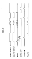
- FIG. 3 is a timing diagram showing a logic flow in the controller 300.
- the high level detector 220 of the controller 200 detects a high level component from the output of the second power amplifier 510 via a coupler 240, i.e., a highest access signal of the subscriber or an oscillation power level.
- the high level detector 220 detects the reverse access signal of the subscriber, a talking signal and an oscillation signal. If the detected level is above a predetermined reference value, i.e., in case of high-level detect, very high access signal or oscillation, the high level detector 220 generates a high-level power detect signal and a delayed detect signal DELAYED DETECT having the same power level as the power level detect signal.
- the high level detector 220 If the power detect signal POWER DETECT is 'high' and the delayed detect signal DELAYED DETECT is 'low', the high level detector 220 generates a rising signal RISING; and otherwise, the high level detector 220 generates a falling signal FALLING.
- the rising and falling signals RISING and FALLING are event triggers.
- the high limit check circuit 215 of the detector check logic circuit 210 turns off the switch SW1 immediately after a predetermined time T1 from generation of the rising signal, and checks the level of the power detect signal POWER DETECT for a predetermined time T2 when the switch SW1 is off. If the power detect signal POWER DETECT has a high level detected during the time T2, the high limit check circuit 215 turns on the switch SW1. Otherwise, if the power detect signal POWER DETECT has a low level detected during the time T2, the switch SW1 is turned off. In a case where a falling signal FALLING is generated prior to the time T1 from generation of the rising signal RISING, the rising signal RISING is generated again and the switch SW1 is not turned off until the time T1.
- the talking signal is continuously 'high' and hardly detected due to characteristic of the CDMA, with the oscillation signal continuously in a 'high' state.
- the switch SW1 is turned on again. If the oscillation signal is detected repeatedly in this case, the system is completely down (in order to protect the base station transceiver system because repeated oscillation implies something wrong, in which case the switch SW1 is not ON even if the subscriber has access to). With the high level signal detected, it is possible to discriminate oscillation signal, terminal access signal and terminal talking signal.
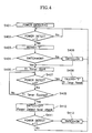
- FIG. 4 is a flowchart explaining an operation for programming the procedure.
- the high limit check circuit 215 determines in step 402 whether the power detect signal S1 is converted from low level "0" (in step 401) to high level "1".
- the high limit check circuit 215 generates a rising signal RISING and determines in step 404 whether the switch SW1 is ON. If the switch SW1 is OFF, the high limit check circuit 215 turns the switch SW1 on and activates the timer during a predetermined time T1, in step 405.
- the high limit check circuit 215 determines in step 407 whether the power detect signal POWER DETECT is "0" after generation of the rising signal RISING, and if the power detect signal is "0", generates a falling signal RISING and resets the timer T1, in step 408.
- the high limit check circuit 215 turns the switch SW1 off and checks the level of the power detect signal POWER DETECT during a predetermined time T2 with the switch SW1 OFF, in step 410.
- the high limit check circuit 215 turns the switch SW1 on, in step 412.
- the high limit check circuit 215 turns the switch SW1 off.
- FIG. 5 is a timing diagram showing a logic flow in the low limit check circuit 213 of the controller 300.
- the low level detector 230 of the controller 200 detects a low level component from the output of the second power amplifier 510 via the coupler 240, i.e., when no subscriber is connected.
- the low level detector 230 detects the reverse access signal of the subscriber, a talking signal and a non-signal output level. If the detected level is below a predetermined reference value, which implies that there is the non-signal output level without a reverse access signal of the subscriber nor a talking signal, the low level detector 230 turns the reverse output off to protect the reverse channel of the base station transceiver system.
- the low level detector 230 compares the detect signal being above a predetermine value to a delayed detect signal delayed detect2 to generate a rising signal RISING2 and a falling signal FALLING2, and after an elapse of a predetermined time T3 from generation of the falling signal FALLING2, turns the switch SW1 off.
- the low level detector 230 turns the switch SW1 on. As such, the reverse output of the repeater system is disabled without a subscriber connection, so that reduction of the reverse capacity of the base station transceiver system due to the repeater system can be improved.
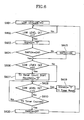
- FIG. 6 is a flowchart explaining an operation for programming the procedure.
- the low limit check circuit 213 determines in step 602 whether the low level detect signal LOW LEVEL DETECT is converted from low level "0" (in step 601) to high level "1".
- the low limit check circuit 213 generates a rising signal RISING2 and determines in step 604 whether the switch SW1 is ON. If the switch SW1 is OFF, the low limit check circuit 213 turns the switch SW1 on and determines in step 606 whether the low level detect signal LOW LEVEL DETECT is "0".
- the low limit check circuit 213 If the low level detect signal LOW LEVEL DETECT is "0", the low limit check circuit 213 generates a falling signal FALLING2 and activates a timer T3, in step 607.
- the low limit check circuit 213 determines in step 608 whether the low level detect signal LOW LEVEL DETECT is "1" after generation of the falling signal FALLING2. If so, the low limit check circuit 213 generates a rising signal RISING2 and resets the timer, in step 609.
- the low limit check circuit 213 turns the switch SW1 off immediately.
- the present invention is not specifically limited to the PCS and may be applied to any general mobile communication system.
- the embodiment of the present invention provides a repeater system and a control method thereof, in which the reverse output of the repeater system is disabled upon detection of a non-subscriber interval in the service area or a reverse oscillation so as to prevent a drop in the capacity of a base station transceiver system and protect a reception path.
Landscapes
- Engineering & Computer Science (AREA)
- Computer Networks & Wireless Communication (AREA)
- Signal Processing (AREA)
- Radio Relay Systems (AREA)
- Mobile Radio Communication Systems (AREA)
- Interface Circuits In Exchanges (AREA)
- Selective Calling Equipment (AREA)
- Arrangements For Transmission Of Measured Signals (AREA)
Priority Applications (4)
| Application Number | Priority Date | Filing Date | Title |
|---|---|---|---|
| AT01104878T ATE407484T1 (de) | 2001-02-28 | 2001-02-28 | Regelverfahren für ein relaissystem mit funktion zum unterdrücken von schwingungen sowie einer automatischen abschaltfunktion des ausgangs für nichtteilnehmer |
| DE60135630T DE60135630D1 (de) | 2001-02-28 | 2001-02-28 | Regelverfahren für ein Relaissystem mit Funktion zum Unterdrücken von Schwingungen sowie einer automatischen Abschaltfunktion des Ausgangs für Nichtteilnehmer |
| EP01104878A EP1237298B1 (de) | 2001-02-28 | 2001-02-28 | Regelverfahren für ein Relaissystem mit Funktion zum Unterdrücken von Schwingungen sowie einer automatischen Abschaltfunktion des Ausgangs für Nichtteilnehmer |
| HK02106794.3A HK1045417B (en) | 2001-02-28 | 2002-09-17 | Control method for a repeater system having oscillation preventing function and automatic reverse output disabling function for non-subscriber |
Applications Claiming Priority (1)
| Application Number | Priority Date | Filing Date | Title |
|---|---|---|---|
| EP01104878A EP1237298B1 (de) | 2001-02-28 | 2001-02-28 | Regelverfahren für ein Relaissystem mit Funktion zum Unterdrücken von Schwingungen sowie einer automatischen Abschaltfunktion des Ausgangs für Nichtteilnehmer |
Publications (2)
| Publication Number | Publication Date |
|---|---|
| EP1237298A1 true EP1237298A1 (de) | 2002-09-04 |
| EP1237298B1 EP1237298B1 (de) | 2008-09-03 |
Family
ID=8176627
Family Applications (1)
| Application Number | Title | Priority Date | Filing Date |
|---|---|---|---|
| EP01104878A Expired - Lifetime EP1237298B1 (de) | 2001-02-28 | 2001-02-28 | Regelverfahren für ein Relaissystem mit Funktion zum Unterdrücken von Schwingungen sowie einer automatischen Abschaltfunktion des Ausgangs für Nichtteilnehmer |
Country Status (4)
| Country | Link |
|---|---|
| EP (1) | EP1237298B1 (de) |
| AT (1) | ATE407484T1 (de) |
| DE (1) | DE60135630D1 (de) |
| HK (1) | HK1045417B (de) |
Cited By (1)
| Publication number | Priority date | Publication date | Assignee | Title |
|---|---|---|---|---|
| US9344141B2 (en) | 2013-07-01 | 2016-05-17 | Industrial Technology Research Institute | Electronic device and data control method |
Citations (3)
| Publication number | Priority date | Publication date | Assignee | Title |
|---|---|---|---|---|
| EP0851606A2 (de) * | 1996-12-30 | 1998-07-01 | Lucent Technologies Inc. | Wiederholer für Telekommunikationssanordnung |
| US5815795A (en) * | 1995-08-25 | 1998-09-29 | Sumitomo Electric Industries, Ltd. | Oscillation detecting system for wireless repeater |
| JPH10313271A (ja) * | 1997-05-12 | 1998-11-24 | Kokusai Electric Co Ltd | 周波数選択形無線中継装置の異常発振検出回路 |
Family Cites Families (1)
| Publication number | Priority date | Publication date | Assignee | Title |
|---|---|---|---|---|
| US3411088A (en) * | 1965-02-09 | 1968-11-12 | Bell Telephone Labor Inc | Automatic input power level adjustment apparatus for amplifier of a broadband repeater |
-
2001
- 2001-02-28 EP EP01104878A patent/EP1237298B1/de not_active Expired - Lifetime
- 2001-02-28 AT AT01104878T patent/ATE407484T1/de not_active IP Right Cessation
- 2001-02-28 DE DE60135630T patent/DE60135630D1/de not_active Expired - Lifetime
-
2002
- 2002-09-17 HK HK02106794.3A patent/HK1045417B/en not_active IP Right Cessation
Patent Citations (3)
| Publication number | Priority date | Publication date | Assignee | Title |
|---|---|---|---|---|
| US5815795A (en) * | 1995-08-25 | 1998-09-29 | Sumitomo Electric Industries, Ltd. | Oscillation detecting system for wireless repeater |
| EP0851606A2 (de) * | 1996-12-30 | 1998-07-01 | Lucent Technologies Inc. | Wiederholer für Telekommunikationssanordnung |
| JPH10313271A (ja) * | 1997-05-12 | 1998-11-24 | Kokusai Electric Co Ltd | 周波数選択形無線中継装置の異常発振検出回路 |
Non-Patent Citations (1)
| Title |
|---|
| PATENT ABSTRACTS OF JAPAN vol. 1999, no. 02 26 February 1999 (1999-02-26) * |
Cited By (1)
| Publication number | Priority date | Publication date | Assignee | Title |
|---|---|---|---|---|
| US9344141B2 (en) | 2013-07-01 | 2016-05-17 | Industrial Technology Research Institute | Electronic device and data control method |
Also Published As
| Publication number | Publication date |
|---|---|
| DE60135630D1 (de) | 2008-10-16 |
| HK1045417A1 (en) | 2002-11-22 |
| EP1237298B1 (de) | 2008-09-03 |
| ATE407484T1 (de) | 2008-09-15 |
| HK1045417B (en) | 2008-11-28 |
Similar Documents
| Publication | Publication Date | Title |
|---|---|---|
| US5950127A (en) | Mode switching method for mobile station | |
| US5023930A (en) | Booster with detectable boost operation | |
| US5152002A (en) | System and method for extending cell site coverage | |
| EP0976272B1 (de) | Verfahren und system zur beseitigung von durch mobile kommunikationsgeräte verursachte störungen | |
| JP2546347B2 (ja) | 無線送受信装置 | |
| US6748194B2 (en) | Repeater system having oscillation preventing function and automatic reverse output disabling function for non-subscriber and control method thereof | |
| US5515365A (en) | Method and apparatus for reducing interference in a time division duplex communication system | |
| US6493537B1 (en) | Apparatus and method for preventing oscillations in a radio repeater device | |
| EP0302455A2 (de) | Booster-Verstärker | |
| US6125138A (en) | Base station transmitter-receiver | |
| EP0746951A1 (de) | Verfahren zur übertragung von anrufen verschiedener priorität in einem zellularen netzwerk | |
| HK1004310B (en) | Booster | |
| US7103321B2 (en) | Power amplifier bypass in a half-duplex IC | |
| KR100385611B1 (ko) | 이동통신시스템의 무선 중계장치 | |
| AU662449B2 (en) | An apparatus and a method for preserving coverage in an overlapping coverage area | |
| KR100573932B1 (ko) | 발진 방지기능 및 무가입자시 역방향 출력 자동 차단 기능을갖는 중계기 시스템 및 그 제어방법 | |
| JPH03231523A (ja) | 移動通信制御方式 | |
| KR20030049031A (ko) | 전력제어 기능을 갖는 중간 주파수 방식의 중계기와전력제어 방법 | |
| EP1237298B1 (de) | Regelverfahren für ein Relaissystem mit Funktion zum Unterdrücken von Schwingungen sowie einer automatischen Abschaltfunktion des Ausgangs für Nichtteilnehmer | |
| JP3809725B2 (ja) | 周波数ホッピング方式を用いた無線通信装置 | |
| KR100287751B1 (ko) | Cdma이동전화특수지역서비스시스템 | |
| KR100376416B1 (ko) | 이동통신 중계기 발진검출 및 방지시스템 | |
| KR100324027B1 (ko) | 중계기의 동작 제어회로 | |
| JP3054901B2 (ja) | 移動無線受信方法および装置 | |
| KR0184488B1 (ko) | 무선호출기의 상호 변조 방지회로 및 방법 |
Legal Events
| Date | Code | Title | Description |
|---|---|---|---|
| PUAI | Public reference made under article 153(3) epc to a published international application that has entered the european phase |
Free format text: ORIGINAL CODE: 0009012 |
|
| 17P | Request for examination filed |
Effective date: 20011027 |
|
| AK | Designated contracting states |
Kind code of ref document: A1 Designated state(s): AT BE CH CY DE DK ES FI FR GB GR IE IT LI LU MC NL PT SE TR |
|
| AX | Request for extension of the european patent |
Free format text: AL;LT;LV;MK;RO;SI |
|
| RAP1 | Party data changed (applicant data changed or rights of an application transferred) |
Owner name: KTFREETEL CO., LTD |
|
| AKX | Designation fees paid | ||
| RBV | Designated contracting states (corrected) |
Designated state(s): AT BE CH CY DE DK ES FI FR GB GR IE IT LI LU MC NL PT SE TR |
|
| REG | Reference to a national code |
Ref country code: DE Ref legal event code: 8566 |
|
| 17Q | First examination report despatched |
Effective date: 20050627 |
|
| 17Q | First examination report despatched |
Effective date: 20050627 |
|
| RTI1 | Title (correction) |
Free format text: CONTROL METHOD FOR A REPEATER SYSTEM HAVING OSCILLATION PREVENTING FUNCTION AND AUTOMATIC REVERSE OUTPUT DISABLING FUNCTION FOR NON-SUBSCRIBER |
|
| GRAP | Despatch of communication of intention to grant a patent |
Free format text: ORIGINAL CODE: EPIDOSNIGR1 |
|
| GRAS | Grant fee paid |
Free format text: ORIGINAL CODE: EPIDOSNIGR3 |
|
| GRAA | (expected) grant |
Free format text: ORIGINAL CODE: 0009210 |
|
| AK | Designated contracting states |
Kind code of ref document: B1 Designated state(s): AT BE CH CY DE DK ES FI FR GB GR IE IT LI LU MC NL PT SE TR |
|
| REG | Reference to a national code |
Ref country code: GB Ref legal event code: FG4D |
|
| REG | Reference to a national code |
Ref country code: CH Ref legal event code: EP |
|
| REG | Reference to a national code |
Ref country code: IE Ref legal event code: FG4D |
|
| REF | Corresponds to: |
Ref document number: 60135630 Country of ref document: DE Date of ref document: 20081016 Kind code of ref document: P |
|
| REG | Reference to a national code |
Ref country code: SE Ref legal event code: TRGR |
|
| REG | Reference to a national code |
Ref country code: HK Ref legal event code: GR Ref document number: 1045417 Country of ref document: HK |
|
| PG25 | Lapsed in a contracting state [announced via postgrant information from national office to epo] |
Ref country code: ES Free format text: LAPSE BECAUSE OF FAILURE TO SUBMIT A TRANSLATION OF THE DESCRIPTION OR TO PAY THE FEE WITHIN THE PRESCRIBED TIME-LIMIT Effective date: 20081214 |
|
| PG25 | Lapsed in a contracting state [announced via postgrant information from national office to epo] |
Ref country code: AT Free format text: LAPSE BECAUSE OF FAILURE TO SUBMIT A TRANSLATION OF THE DESCRIPTION OR TO PAY THE FEE WITHIN THE PRESCRIBED TIME-LIMIT Effective date: 20080903 |
|
| PG25 | Lapsed in a contracting state [announced via postgrant information from national office to epo] |
Ref country code: BE Free format text: LAPSE BECAUSE OF FAILURE TO SUBMIT A TRANSLATION OF THE DESCRIPTION OR TO PAY THE FEE WITHIN THE PRESCRIBED TIME-LIMIT Effective date: 20080903 |
|
| PG25 | Lapsed in a contracting state [announced via postgrant information from national office to epo] |
Ref country code: PT Free format text: LAPSE BECAUSE OF FAILURE TO SUBMIT A TRANSLATION OF THE DESCRIPTION OR TO PAY THE FEE WITHIN THE PRESCRIBED TIME-LIMIT Effective date: 20090203 |
|
| PLBE | No opposition filed within time limit |
Free format text: ORIGINAL CODE: 0009261 |
|
| STAA | Information on the status of an ep patent application or granted ep patent |
Free format text: STATUS: NO OPPOSITION FILED WITHIN TIME LIMIT |
|
| PG25 | Lapsed in a contracting state [announced via postgrant information from national office to epo] |
Ref country code: DK Free format text: LAPSE BECAUSE OF FAILURE TO SUBMIT A TRANSLATION OF THE DESCRIPTION OR TO PAY THE FEE WITHIN THE PRESCRIBED TIME-LIMIT Effective date: 20080903 |
|
| 26N | No opposition filed |
Effective date: 20090604 |
|
| PG25 | Lapsed in a contracting state [announced via postgrant information from national office to epo] |
Ref country code: IT Free format text: LAPSE BECAUSE OF FAILURE TO SUBMIT A TRANSLATION OF THE DESCRIPTION OR TO PAY THE FEE WITHIN THE PRESCRIBED TIME-LIMIT Effective date: 20080903 |
|
| PG25 | Lapsed in a contracting state [announced via postgrant information from national office to epo] |
Ref country code: MC Free format text: LAPSE BECAUSE OF NON-PAYMENT OF DUE FEES Effective date: 20090228 |
|
| REG | Reference to a national code |
Ref country code: CH Ref legal event code: PL |
|
| PG25 | Lapsed in a contracting state [announced via postgrant information from national office to epo] |
Ref country code: LI Free format text: LAPSE BECAUSE OF NON-PAYMENT OF DUE FEES Effective date: 20090228 Ref country code: CH Free format text: LAPSE BECAUSE OF NON-PAYMENT OF DUE FEES Effective date: 20090228 |
|
| PG25 | Lapsed in a contracting state [announced via postgrant information from national office to epo] |
Ref country code: IE Free format text: LAPSE BECAUSE OF NON-PAYMENT OF DUE FEES Effective date: 20090228 |
|
| PG25 | Lapsed in a contracting state [announced via postgrant information from national office to epo] |
Ref country code: GR Free format text: LAPSE BECAUSE OF FAILURE TO SUBMIT A TRANSLATION OF THE DESCRIPTION OR TO PAY THE FEE WITHIN THE PRESCRIBED TIME-LIMIT Effective date: 20081204 |
|
| PG25 | Lapsed in a contracting state [announced via postgrant information from national office to epo] |
Ref country code: LU Free format text: LAPSE BECAUSE OF NON-PAYMENT OF DUE FEES Effective date: 20090228 |
|
| PG25 | Lapsed in a contracting state [announced via postgrant information from national office to epo] |
Ref country code: TR Free format text: LAPSE BECAUSE OF FAILURE TO SUBMIT A TRANSLATION OF THE DESCRIPTION OR TO PAY THE FEE WITHIN THE PRESCRIBED TIME-LIMIT Effective date: 20080903 |
|
| PG25 | Lapsed in a contracting state [announced via postgrant information from national office to epo] |
Ref country code: CY Free format text: LAPSE BECAUSE OF FAILURE TO SUBMIT A TRANSLATION OF THE DESCRIPTION OR TO PAY THE FEE WITHIN THE PRESCRIBED TIME-LIMIT Effective date: 20080903 |
|
| REG | Reference to a national code |
Ref country code: FR Ref legal event code: PLFP Year of fee payment: 16 |
|
| REG | Reference to a national code |
Ref country code: FR Ref legal event code: PLFP Year of fee payment: 17 |
|
| REG | Reference to a national code |
Ref country code: FR Ref legal event code: PLFP Year of fee payment: 18 |
|
| PGFP | Annual fee paid to national office [announced via postgrant information from national office to epo] |
Ref country code: DE Payment date: 20190122 Year of fee payment: 19 Ref country code: GB Payment date: 20190125 Year of fee payment: 19 Ref country code: NL Payment date: 20190128 Year of fee payment: 19 Ref country code: FI Payment date: 20190123 Year of fee payment: 19 Ref country code: FR Payment date: 20190123 Year of fee payment: 19 |
|
| PGFP | Annual fee paid to national office [announced via postgrant information from national office to epo] |
Ref country code: SE Payment date: 20190128 Year of fee payment: 19 |
|
| REG | Reference to a national code |
Ref country code: DE Ref legal event code: R119 Ref document number: 60135630 Country of ref document: DE |
|
| REG | Reference to a national code |
Ref country code: FI Ref legal event code: MAE |
|
| REG | Reference to a national code |
Ref country code: NL Ref legal event code: MM Effective date: 20200301 |
|
| GBPC | Gb: european patent ceased through non-payment of renewal fee |
Effective date: 20200228 |
|
| PG25 | Lapsed in a contracting state [announced via postgrant information from national office to epo] |
Ref country code: FI Free format text: LAPSE BECAUSE OF NON-PAYMENT OF DUE FEES Effective date: 20200228 |
|
| PG25 | Lapsed in a contracting state [announced via postgrant information from national office to epo] |
Ref country code: NL Free format text: LAPSE BECAUSE OF NON-PAYMENT OF DUE FEES Effective date: 20200301 |
|
| PG25 | Lapsed in a contracting state [announced via postgrant information from national office to epo] |
Ref country code: FR Free format text: LAPSE BECAUSE OF NON-PAYMENT OF DUE FEES Effective date: 20200229 Ref country code: SE Free format text: LAPSE BECAUSE OF NON-PAYMENT OF DUE FEES Effective date: 20200229 Ref country code: GB Free format text: LAPSE BECAUSE OF NON-PAYMENT OF DUE FEES Effective date: 20200228 Ref country code: DE Free format text: LAPSE BECAUSE OF NON-PAYMENT OF DUE FEES Effective date: 20200901 |