EP1237267A3 - Converter - Google Patents
Converter Download PDFInfo
- Publication number
- EP1237267A3 EP1237267A3 EP02100196A EP02100196A EP1237267A3 EP 1237267 A3 EP1237267 A3 EP 1237267A3 EP 02100196 A EP02100196 A EP 02100196A EP 02100196 A EP02100196 A EP 02100196A EP 1237267 A3 EP1237267 A3 EP 1237267A3
- Authority
- EP
- European Patent Office
- Prior art keywords
- voltage
- converter
- output
- full
- circuit
- Prior art date
- Legal status (The legal status is an assumption and is not a legal conclusion. Google has not performed a legal analysis and makes no representation as to the accuracy of the status listed.)
- Withdrawn
Links
Classifications
-
- H—ELECTRICITY
- H02—GENERATION; CONVERSION OR DISTRIBUTION OF ELECTRIC POWER
- H02M—APPARATUS FOR CONVERSION BETWEEN AC AND AC, BETWEEN AC AND DC, OR BETWEEN DC AND DC, AND FOR USE WITH MAINS OR SIMILAR POWER SUPPLY SYSTEMS; CONVERSION OF DC OR AC INPUT POWER INTO SURGE OUTPUT POWER; CONTROL OR REGULATION THEREOF
- H02M3/00—Conversion of DC power input into DC power output
- H02M3/22—Conversion of DC power input into DC power output with intermediate conversion into AC
- H02M3/24—Conversion of DC power input into DC power output with intermediate conversion into AC by static converters
- H02M3/28—Conversion of DC power input into DC power output with intermediate conversion into AC by static converters using discharge tubes with control electrode or semiconductor devices with control electrode to produce the intermediate AC
- H02M3/325—Conversion of DC power input into DC power output with intermediate conversion into AC by static converters using discharge tubes with control electrode or semiconductor devices with control electrode to produce the intermediate AC using devices of a triode or a transistor type requiring continuous application of a control signal
- H02M3/335—Conversion of DC power input into DC power output with intermediate conversion into AC by static converters using discharge tubes with control electrode or semiconductor devices with control electrode to produce the intermediate AC using devices of a triode or a transistor type requiring continuous application of a control signal using semiconductor devices only
- H02M3/337—Conversion of DC power input into DC power output with intermediate conversion into AC by static converters using discharge tubes with control electrode or semiconductor devices with control electrode to produce the intermediate AC using devices of a triode or a transistor type requiring continuous application of a control signal using semiconductor devices only in push-pull configuration
- H02M3/3376—Conversion of DC power input into DC power output with intermediate conversion into AC by static converters using discharge tubes with control electrode or semiconductor devices with control electrode to produce the intermediate AC using devices of a triode or a transistor type requiring continuous application of a control signal using semiconductor devices only in push-pull configuration with automatic control of output voltage or current
-
- H—ELECTRICITY
- H02—GENERATION; CONVERSION OR DISTRIBUTION OF ELECTRIC POWER
- H02M—APPARATUS FOR CONVERSION BETWEEN AC AND AC, BETWEEN AC AND DC, OR BETWEEN DC AND DC, AND FOR USE WITH MAINS OR SIMILAR POWER SUPPLY SYSTEMS; CONVERSION OF DC OR AC INPUT POWER INTO SURGE OUTPUT POWER; CONTROL OR REGULATION THEREOF
- H02M3/00—Conversion of DC power input into DC power output
- H02M3/22—Conversion of DC power input into DC power output with intermediate conversion into AC
- H02M3/24—Conversion of DC power input into DC power output with intermediate conversion into AC by static converters
- H02M3/28—Conversion of DC power input into DC power output with intermediate conversion into AC by static converters using discharge tubes with control electrode or semiconductor devices with control electrode to produce the intermediate AC
-
- H—ELECTRICITY
- H02—GENERATION; CONVERSION OR DISTRIBUTION OF ELECTRIC POWER
- H02M—APPARATUS FOR CONVERSION BETWEEN AC AND AC, BETWEEN AC AND DC, OR BETWEEN DC AND DC, AND FOR USE WITH MAINS OR SIMILAR POWER SUPPLY SYSTEMS; CONVERSION OF DC OR AC INPUT POWER INTO SURGE OUTPUT POWER; CONTROL OR REGULATION THEREOF
- H02M1/00—Details of apparatus for conversion
- H02M1/0003—Details of control, feedback or regulation circuits
- H02M1/0012—Control circuits using digital or numerical techniques
Landscapes
- Engineering & Computer Science (AREA)
- Power Engineering (AREA)
- Dc-Dc Converters (AREA)
- Inverter Devices (AREA)
Abstract
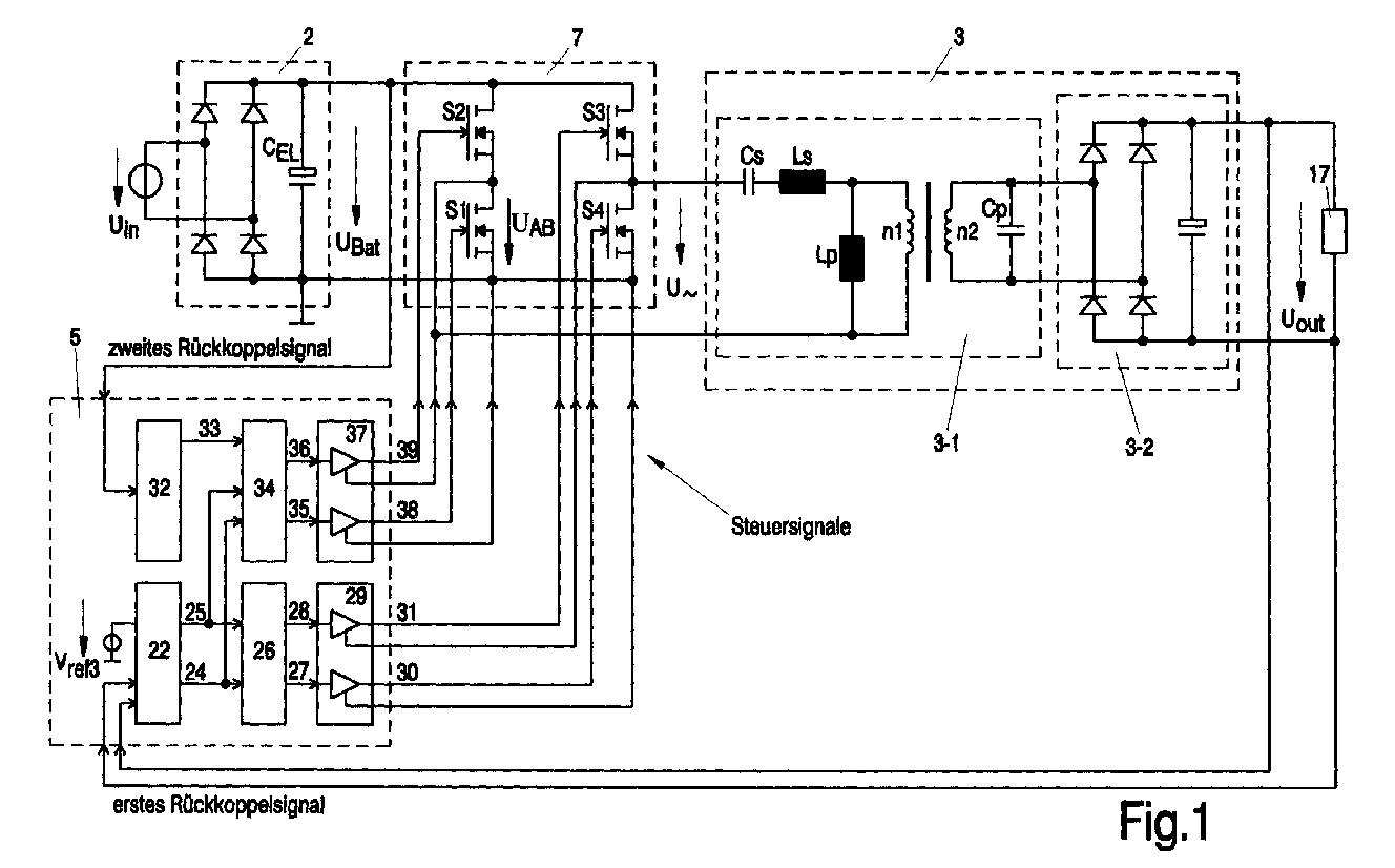
Die Erfindung betrifft einen Konverter zum Umsetzen einer DC-Spannung UBat in eine
Ausgangs-Gleichspannung Uout, insbesondere bei TV- oder Computerbildschirmen. Der
Konverter umfasst eine Vollbrückenschaltung 7 zum Zerhacken der DC-Spannung UBat in
eine AC-Spannung U∼ an ihrem Ausgang und einen Schaltkreis 3 zum Umwandeln der
AC-Spannung U∼ in die Ausgangs-Gleichspannung Uout des Konverters. Der Konverter
umfasst weiterhin eine Steuerschaltung 5 zum Erzeugen von Steuersignalen zum Ansteuern
von steuerbaren Schaltelementen S1 ... S4 in der Vollbrückenschaltung. Es ist die Aufgabe
der Erfindung, einen derartigen Konverter so weiterzubilden, dass die von ihm erzeugte
Ausgangsspannung Uout auch während einer Umschaltung der Vollbrückenschaltung
zwischen zwei Betriebsmodi stabil bleibt. Diese Aufgabe wird erfindungsgemäß dadurch
gelöst, dass die Steuerschaltung 5 diese Umschaltung nur während eines Totzeitintervalls
ttot vornimmt, währenddessen zumindest eines der Schaltelemente S1 ... S4 ausgeschaltet
ist.
Applications Claiming Priority (2)
| Application Number | Priority Date | Filing Date | Title |
|---|---|---|---|
| DE10109967A DE10109967A1 (en) | 2001-03-01 | 2001-03-01 | converter |
| DE10109967 | 2001-03-01 |
Publications (2)
| Publication Number | Publication Date |
|---|---|
| EP1237267A2 EP1237267A2 (en) | 2002-09-04 |
| EP1237267A3 true EP1237267A3 (en) | 2004-03-03 |
Family
ID=7675995
Family Applications (1)
| Application Number | Title | Priority Date | Filing Date |
|---|---|---|---|
| EP02100196A Withdrawn EP1237267A3 (en) | 2001-03-01 | 2002-02-28 | Converter |
Country Status (5)
| Country | Link |
|---|---|
| US (1) | US6643146B2 (en) |
| EP (1) | EP1237267A3 (en) |
| JP (1) | JP2002281754A (en) |
| CN (1) | CN1374740B (en) |
| DE (1) | DE10109967A1 (en) |
Families Citing this family (30)
| Publication number | Priority date | Publication date | Assignee | Title |
|---|---|---|---|---|
| CN100403646C (en) * | 2004-02-23 | 2008-07-16 | 联昌电子企业股份有限公司 | Circuit for driving full-bridge type current converter by using push-pull type control chip |
| DE102004035248B4 (en) | 2004-07-21 | 2011-08-18 | Puls GmbH, 81925 | resonant converter |
| JP4582318B2 (en) * | 2005-02-23 | 2010-11-17 | ミツミ電機株式会社 | Resonant power supply |
| EP1878107B1 (en) * | 2005-04-26 | 2012-08-15 | Koninklijke Philips Electronics N.V. | Resonant dc/dc converter with zero current switching |
| WO2007116444A1 (en) * | 2006-03-30 | 2007-10-18 | Fujitsu Limited | Power supply apparatus and power supply control method |
| US20090085543A1 (en) * | 2007-09-28 | 2009-04-02 | Astec International Limited | Variable Output Voltage Power Converter |
| US8242754B2 (en) * | 2009-08-14 | 2012-08-14 | System General Corp. | Resonant power converter with half bridge and full bridge operations and method for control thereof |
| DE102009047572A1 (en) * | 2009-12-07 | 2011-06-09 | Osram Gesellschaft mit beschränkter Haftung | Circuit arrangement for operating at least one discharge lamp |
| CN103259391A (en) * | 2012-02-21 | 2013-08-21 | 凹凸电子(武汉)有限公司 | Load driving circuit, power converter and controller |
| US10343535B2 (en) | 2010-04-08 | 2019-07-09 | Witricity Corporation | Wireless power antenna alignment adjustment system for vehicles |
| US9561730B2 (en) * | 2010-04-08 | 2017-02-07 | Qualcomm Incorporated | Wireless power transmission in electric vehicles |
| US8264265B2 (en) * | 2010-09-30 | 2012-09-11 | Kimberly-Clark Worldwide, Inc. | Automatic darkening filter (ADF) eye protection device with improved drive circuitry |
| DE102010060957A1 (en) * | 2010-12-02 | 2012-06-06 | Sma Solar Technology Ag | Method for operating a DC-DC converter |
| US9948204B2 (en) | 2011-05-19 | 2018-04-17 | Enphase Energy, Inc. | Method and apparatus for controlling resonant converter output power |
| CN102510223A (en) * | 2011-11-03 | 2012-06-20 | 东文高压电源(天津)有限公司 | Quasi-resonant half-bridge type adjustable high-voltage power circuit |
| JP6017804B2 (en) * | 2012-03-09 | 2016-11-02 | シャープ株式会社 | DC / DC converter and system |
| US20150180345A1 (en) * | 2012-07-19 | 2015-06-25 | Damien Frost | Multi-mode control of a full bridge resonant converter |
| CN103997219B (en) * | 2013-02-20 | 2017-04-12 | 台达电子工业股份有限公司 | Power converter and power conversion method |
| US20150049515A1 (en) * | 2013-08-13 | 2015-02-19 | Delphi Technologies, Inc. | Resonant converter and method of operating the same |
| CN103618461B (en) * | 2013-12-10 | 2017-10-13 | 广东易事特电源股份有限公司 | The control method and control device of a kind of bridge conversion circuit |
| CN104811041B (en) * | 2014-01-29 | 2019-03-05 | 维谛技术有限公司 | A kind of resonance circuit |
| US9627979B2 (en) * | 2014-10-03 | 2017-04-18 | Bombardier Transportation Gmbh | Dual mode DC-DC converter |
| JP6390450B2 (en) * | 2015-01-26 | 2018-09-19 | 株式会社デンソー | Power transmission device for contactless power supply system |
| JP6004555B1 (en) * | 2015-09-11 | 2016-10-12 | Hoya Candeo Optronics株式会社 | Switching power supply device and light irradiation device including the same |
| US11043847B2 (en) | 2015-09-25 | 2021-06-22 | The Hong Kong University Of Science And Technology | Wireless charging receiver |
| KR101769335B1 (en) * | 2015-10-22 | 2017-08-18 | 월드탑텍(주) | Dc/dc converter for using multi topology |
| US10038390B1 (en) * | 2017-03-16 | 2018-07-31 | Kabushiki Kaisha Toshiba | Power conversion circuit |
| US10097102B1 (en) * | 2017-03-16 | 2018-10-09 | Kabushiki Kaisha Toshiba | Power conversion circuit |
| CN109921670B (en) * | 2019-03-28 | 2021-01-19 | 苏州汇川联合动力系统有限公司 | Inverter control method, inverter and readable storage medium |
| CN112769204B (en) * | 2020-12-29 | 2023-05-23 | Oppo广东移动通信有限公司 | Power supply device, charging method and system |
Citations (4)
| Publication number | Priority date | Publication date | Assignee | Title |
|---|---|---|---|---|
| US4742442A (en) * | 1986-06-17 | 1988-05-03 | Nilssen Ole K | Controlled magnetron power supply including dual-mode inverter |
| US5189602A (en) * | 1989-05-12 | 1993-02-23 | General Electric Cgr S.A. | High-voltage generator with selective half-bridge and full-bridge operation |
| EP0838893A2 (en) * | 1996-10-28 | 1998-04-29 | Sony Corporation | Power source apparatus |
| US5859771A (en) * | 1996-07-31 | 1999-01-12 | Transtechnik Gmbh | Half/full bridge converter |
Family Cites Families (8)
| Publication number | Priority date | Publication date | Assignee | Title |
|---|---|---|---|---|
| US4628426A (en) * | 1985-10-31 | 1986-12-09 | General Electric Company | Dual output DC-DC converter with independently controllable output voltages |
| US4672528A (en) * | 1986-05-27 | 1987-06-09 | General Electric Company | Resonant inverter with improved control |
| US4855888A (en) * | 1988-10-19 | 1989-08-08 | Unisys Corporation | Constant frequency resonant power converter with zero voltage switching |
| DE19529941A1 (en) | 1995-08-16 | 1997-02-20 | Philips Patentverwaltung | Voltage converter |
| KR100199506B1 (en) * | 1996-10-29 | 1999-06-15 | 윤문수 | A zero voltage/current switching circuit for reduced ripple current of the full-bridge dc/dc converter |
| JP3318240B2 (en) * | 1997-09-12 | 2002-08-26 | 松下電器産業株式会社 | Switching power supply |
| US6442047B1 (en) * | 1999-10-08 | 2002-08-27 | Lambda Electronics, Inc. | Power conversion apparatus and methods with reduced current and voltage switching |
| DE60009043T2 (en) * | 1999-12-18 | 2004-09-30 | Koninklijke Philips Electronics N.V. | CONVERTER WITH RESONANT CIRCUIT ELEMENTS |
-
2001
- 2001-03-01 DE DE10109967A patent/DE10109967A1/en not_active Withdrawn
-
2002
- 2002-02-25 US US10/084,737 patent/US6643146B2/en not_active Expired - Fee Related
- 2002-02-26 CN CN021080976A patent/CN1374740B/en not_active Expired - Fee Related
- 2002-02-28 EP EP02100196A patent/EP1237267A3/en not_active Withdrawn
- 2002-02-28 JP JP2002052979A patent/JP2002281754A/en not_active Ceased
Patent Citations (4)
| Publication number | Priority date | Publication date | Assignee | Title |
|---|---|---|---|---|
| US4742442A (en) * | 1986-06-17 | 1988-05-03 | Nilssen Ole K | Controlled magnetron power supply including dual-mode inverter |
| US5189602A (en) * | 1989-05-12 | 1993-02-23 | General Electric Cgr S.A. | High-voltage generator with selective half-bridge and full-bridge operation |
| US5859771A (en) * | 1996-07-31 | 1999-01-12 | Transtechnik Gmbh | Half/full bridge converter |
| EP0838893A2 (en) * | 1996-10-28 | 1998-04-29 | Sony Corporation | Power source apparatus |
Also Published As
| Publication number | Publication date |
|---|---|
| CN1374740A (en) | 2002-10-16 |
| US6643146B2 (en) | 2003-11-04 |
| CN1374740B (en) | 2010-05-26 |
| US20020126515A1 (en) | 2002-09-12 |
| EP1237267A2 (en) | 2002-09-04 |
| JP2002281754A (en) | 2002-09-27 |
| DE10109967A1 (en) | 2002-09-12 |
Similar Documents
| Publication | Publication Date | Title |
|---|---|---|
| EP1237267A3 (en) | Converter | |
| ATE268956T1 (en) | METHOD FOR OPERATING A MATRIX CONVERTER AND MATRIX CONVERTER FOR IMPLEMENTING THE METHOD | |
| DE69832220T2 (en) | Cost-effective current transformer with high efficiency | |
| EP1083654A3 (en) | Motor drive unit and method of detecting malfunction of the motor drive unit | |
| EP0982841A3 (en) | Pulse-width modulated d.c.-d.c. converter | |
| EP1499308A4 (en) | Tri-substituted heteroaryls and methods of making and using the same | |
| EA200401061A1 (en) | CATALYTIC COMPOSITIONS, INCLUDING MOLECULAR SITES, THEIR PREPARATION AND APPLICATION IN THE TRANSITION PROCESS | |
| EP1220580A3 (en) | Drive device and drive method for a cold cathode fluorescent lamp | |
| EP1148621A3 (en) | Charge pump device | |
| DE102004047399A1 (en) | Simplified topology for HID lamps | |
| EP1235334A3 (en) | Gate driver for thyristor | |
| EP0938922A3 (en) | Fluidized bed reactor and its use | |
| EP1249925A3 (en) | DC/DC-converter | |
| EP1289109A3 (en) | Soft-switching power supply | |
| EP1708346A3 (en) | Active primary side circuit for a switch mode power supply | |
| EP1148768A3 (en) | Stabilization of gas dicharge lamps operation | |
| EP1069672A3 (en) | Power supply with transformer choke | |
| EP3284319A1 (en) | Converter for light sources | |
| EP1014550A3 (en) | An AC/DC converter | |
| EP1760872A3 (en) | Inverter circuit free from power-source-voltage fluctuation | |
| EP1306287A3 (en) | Power steering apparatus | |
| EP1475881A3 (en) | Power converter | |
| EP1589645A3 (en) | Circuit for converting an AC voltage into a DC voltage | |
| EP1311003A3 (en) | Method of charging and discharging a piezoelectric element | |
| EP1643623A3 (en) | Inverter and inverter driving method for enabling soft start of a load |
Legal Events
| Date | Code | Title | Description |
|---|---|---|---|
| PUAI | Public reference made under article 153(3) epc to a published international application that has entered the european phase |
Free format text: ORIGINAL CODE: 0009012 |
|
| AK | Designated contracting states |
Kind code of ref document: A2 Designated state(s): AT BE CH CY DE DK ES FI FR GB GR IE IT LI LU MC NL PT SE TR |
|
| AX | Request for extension of the european patent |
Free format text: AL;LT;LV;MK;RO;SI |
|
| RAP1 | Party data changed (applicant data changed or rights of an application transferred) |
Owner name: KONINKLIJKE PHILIPS ELECTRONICS N.V. Owner name: PHILIPS CORPORATE INTELLECTUAL PROPERTY GMBH |
|
| RAP1 | Party data changed (applicant data changed or rights of an application transferred) |
Owner name: KONINKLIJKE PHILIPS ELECTRONICS N.V. Owner name: PHILIPS INTELLECTUAL PROPERTY & STANDARDS GMBH |
|
| PUAL | Search report despatched |
Free format text: ORIGINAL CODE: 0009013 |
|
| AK | Designated contracting states |
Kind code of ref document: A3 Designated state(s): AT BE CH CY DE DK ES FI FR GB GR IE IT LI LU MC NL PT SE TR |
|
| AX | Request for extension of the european patent |
Extension state: AL LT LV MK RO SI |
|
| RIC1 | Information provided on ipc code assigned before grant |
Ipc: 7H 02M 1/10 B Ipc: 7H 02M 3/337 B Ipc: 7H 02M 3/28 A |
|
| 17P | Request for examination filed |
Effective date: 20040903 |
|
| AKX | Designation fees paid |
Designated state(s): AT BE CH CY DE DK ES FI FR GB GR IE IT LI LU MC NL PT SE TR |
|
| 17Q | First examination report despatched |
Effective date: 20050204 |
|
| GRAP | Despatch of communication of intention to grant a patent |
Free format text: ORIGINAL CODE: EPIDOSNIGR1 |
|
| STAA | Information on the status of an ep patent application or granted ep patent |
Free format text: STATUS: THE APPLICATION IS DEEMED TO BE WITHDRAWN |
|
| 18D | Application deemed to be withdrawn |
Effective date: 20071206 |