EP1237237B1 - Braid folding unit and a braid folding method of a shielded wire - Google Patents
Braid folding unit and a braid folding method of a shielded wire Download PDFInfo
- Publication number
- EP1237237B1 EP1237237B1 EP02004767A EP02004767A EP1237237B1 EP 1237237 B1 EP1237237 B1 EP 1237237B1 EP 02004767 A EP02004767 A EP 02004767A EP 02004767 A EP02004767 A EP 02004767A EP 1237237 B1 EP1237237 B1 EP 1237237B1
- Authority
- EP
- European Patent Office
- Prior art keywords
- braid
- shielded wire
- expanding
- wire
- pipe
- Prior art date
- Legal status (The legal status is an assumption and is not a legal conclusion. Google has not performed a legal analysis and makes no representation as to the accuracy of the status listed.)
- Expired - Lifetime
Links
- 238000000034 method Methods 0.000 title claims description 10
- 238000010009 beating Methods 0.000 claims description 2
- 239000002184 metal Substances 0.000 description 7
- 238000002788 crimping Methods 0.000 description 6
- 238000003780 insertion Methods 0.000 description 5
- 230000037431 insertion Effects 0.000 description 5
- 238000005520 cutting process Methods 0.000 description 4
- 239000006185 dispersion Substances 0.000 description 3
- 238000004519 manufacturing process Methods 0.000 description 3
- 239000004020 conductor Substances 0.000 description 2
- 238000012986 modification Methods 0.000 description 2
- 230000004048 modification Effects 0.000 description 2
- 235000008331 Pinus X rigitaeda Nutrition 0.000 description 1
- 235000011613 Pinus brutia Nutrition 0.000 description 1
- 241000018646 Pinus brutia Species 0.000 description 1
- 238000005452 bending Methods 0.000 description 1
- 230000001419 dependent effect Effects 0.000 description 1
- 239000000835 fiber Substances 0.000 description 1
- 238000003754 machining Methods 0.000 description 1
- 238000003672 processing method Methods 0.000 description 1
- 238000004080 punching Methods 0.000 description 1
- 230000006641 stabilisation Effects 0.000 description 1
- 238000003466 welding Methods 0.000 description 1
Images


Classifications
-
- H—ELECTRICITY
- H01—ELECTRIC ELEMENTS
- H01R—ELECTRICALLY-CONDUCTIVE CONNECTIONS; STRUCTURAL ASSOCIATIONS OF A PLURALITY OF MUTUALLY-INSULATED ELECTRICAL CONNECTING ELEMENTS; COUPLING DEVICES; CURRENT COLLECTORS
- H01R43/00—Apparatus or processes specially adapted for manufacturing, assembling, maintaining, or repairing of line connectors or current collectors or for joining electric conductors
- H01R43/04—Apparatus or processes specially adapted for manufacturing, assembling, maintaining, or repairing of line connectors or current collectors or for joining electric conductors for forming connections by deformation, e.g. crimping tool
- H01R43/048—Crimping apparatus or processes
- H01R43/05—Crimping apparatus or processes with wire-insulation stripping
-
- H—ELECTRICITY
- H01—ELECTRIC ELEMENTS
- H01R—ELECTRICALLY-CONDUCTIVE CONNECTIONS; STRUCTURAL ASSOCIATIONS OF A PLURALITY OF MUTUALLY-INSULATED ELECTRICAL CONNECTING ELEMENTS; COUPLING DEVICES; CURRENT COLLECTORS
- H01R43/00—Apparatus or processes specially adapted for manufacturing, assembling, maintaining, or repairing of line connectors or current collectors or for joining electric conductors
- H01R43/28—Apparatus or processes specially adapted for manufacturing, assembling, maintaining, or repairing of line connectors or current collectors or for joining electric conductors for wire processing before connecting to contact members, not provided for in groups H01R43/02 - H01R43/26
-
- H—ELECTRICITY
- H01—ELECTRIC ELEMENTS
- H01R—ELECTRICALLY-CONDUCTIVE CONNECTIONS; STRUCTURAL ASSOCIATIONS OF A PLURALITY OF MUTUALLY-INSULATED ELECTRICAL CONNECTING ELEMENTS; COUPLING DEVICES; CURRENT COLLECTORS
- H01R43/00—Apparatus or processes specially adapted for manufacturing, assembling, maintaining, or repairing of line connectors or current collectors or for joining electric conductors
- H01R43/04—Apparatus or processes specially adapted for manufacturing, assembling, maintaining, or repairing of line connectors or current collectors or for joining electric conductors for forming connections by deformation, e.g. crimping tool
- H01R43/058—Crimping mandrels
- H01R43/0585—Crimping mandrels for crimping apparatus with more than two radially actuated mandrels
-
- H—ELECTRICITY
- H01—ELECTRIC ELEMENTS
- H01R—ELECTRICALLY-CONDUCTIVE CONNECTIONS; STRUCTURAL ASSOCIATIONS OF A PLURALITY OF MUTUALLY-INSULATED ELECTRICAL CONNECTING ELEMENTS; COUPLING DEVICES; CURRENT COLLECTORS
- H01R9/00—Structural associations of a plurality of mutually-insulated electrical connecting elements, e.g. terminal strips or terminal blocks; Terminals or binding posts mounted upon a base or in a case; Bases therefor
- H01R9/03—Connectors arranged to contact a plurality of the conductors of a multiconductor cable, e.g. tapping connections
- H01R9/05—Connectors arranged to contact a plurality of the conductors of a multiconductor cable, e.g. tapping connections for coaxial cables
- H01R9/0518—Connection to outer conductor by crimping or by crimping ferrule
-
- Y—GENERAL TAGGING OF NEW TECHNOLOGICAL DEVELOPMENTS; GENERAL TAGGING OF CROSS-SECTIONAL TECHNOLOGIES SPANNING OVER SEVERAL SECTIONS OF THE IPC; TECHNICAL SUBJECTS COVERED BY FORMER USPC CROSS-REFERENCE ART COLLECTIONS [XRACs] AND DIGESTS
- Y10—TECHNICAL SUBJECTS COVERED BY FORMER USPC
- Y10T—TECHNICAL SUBJECTS COVERED BY FORMER US CLASSIFICATION
- Y10T29/00—Metal working
- Y10T29/49—Method of mechanical manufacture
- Y10T29/49002—Electrical device making
- Y10T29/49117—Conductor or circuit manufacturing
- Y10T29/49123—Co-axial cable
Definitions
- the present invention relates to a braid folding unit and a braid folding method of a shielded wire, wherein a braid of a relatively large-diameter shielded wire used for an electric vehicle and the like can be automatically efficiently folded back toward a shield contactor.
- a sheath outer cover
- a shield contactor made of conductive metal
- the braid is folded back toward the shield contactor.
- a shield pipe made of conductive metal is applied over the wire by hand, and the shield pipe is crimped by a crimping device in a state that the braid is put between the shield contactor and the shield pipe.
- a connecting flange is fitted to the shield pipe, and the connecting flange is grounded to a vehicle body.
- the terminal is connected to a motor, an inverter or a battery of the electric vehicle.
- DE 40 27 904 A1 is disclosed a method and a device for machining shielded electric cables, wherein upon pilling off a cable the ends of the conductors of the cable inclusive of the fibers for stabilisation are inserted in the mouthpiece of a turn up element, wherein the shielding braid is tuned up by further advancing the cable against the mouthpiece and by the shape of the mouthpiece.
- an object of the present invention is to provide a braid folding unit and a braid folding method of a shielded wire, wherein a braid of a relatively large-diameter shielded wire used for an electric vehicle and the like can be automatically efficiently folded back toward a shield contactor.
- a braid folding unit of a shielded wire comprises: a primary expanding means to beat a braid exposed on an inner cover of the shielded wire so as to outwardly expand the braid; an expanding pipe to enter an inside of the braid along the inner cover so as to further outwardly expand the braid; wherein the expanding pipe has an inner bore diameter which is larger than the outside diameter of the inner cover and being openable and closable by an opening-closing means, and the braid can be further expanded by opening the expanding pipe and a braid folding member formed to advance along an outside surface of the closed expanding pipe so as to push the braid in an axial direction of the shielded wire and to fold back the braid over the outer surface of a shield contactor disposed on the shielded wire.
- the braid can be expanded large by two means of the braid primary expanding means and the expanding pipe, the folding of the braid by the braid folding member can be carried out without dispersion of the folding angle. By this, the fitting of the shield pipe on the folded braid at the next step can be securely carried out, thereby improving the product quality. And, because the opening Operation and the folding Operation are sequentially automatically carried out, man-hours required for folding the braid and the manufacturing cost can be reduced.
- the primary expanding means has a pair of openable-and-closable expanding teeth, a pair of sliding members fixing the respective expanding teeth, and a driving means to open and close the pair of sliding members in opposite directions.
- a pair of sliders open or close integrally with the respective expanding teeth by a driving means and the braid of the shielded wire is repeatedly pressed by the expanding teeth, thereby expanding the braid in a bell-like shape.
- a braid folding method of a shielded wire comprises the steps of: beating a braid exposed on an inner cover of the shielded wire by a primary expanding means so as to outwardly expand the braid; entering an expanding pipe into an inside of the braid along the inner cover so as to further outwardly expand the braid by an end sloping portion of the expanding pipe, wherein the braid can be further outwardly expanded by opening the openable-and-closable expanding pipe; and advancing a braid folding member along an outside surface of the expanding pipe so as to push the braid in an axial direction of the shielded wire and to fold back the braid over the outer surface of a contactor disposed on the shielded wire.
- the braid can be expanded large by two means of the braid primary expanding means and the expanding pipe, the folding of the braid by the braid folding member can be carried out without dispersion of the folding angle. By this, the fitting of the shield pipe on the folded braid at the next Step can be securely carried out, thereby improving the product quality. And, because the opening operation and the folding operation are sequentially automatically carried out, man-hours required for folding the braid and the manufacturing cost can be reduced.
- FIG.1 is a perspective view showing an embodiment of a shielded wire processing apparatus including the inventive braid folding unit of a shielded wire.
- This shielded wire processing apparatus 1 has, successively from the right, a console 2 to change the article number, automatic/manual operation and so on, a wire setting unit 3, a shield contactor insertion unit 4, a sheath cutting unit 5, a sheath pulling out unit 6, a braid cutting unit 7, a braid folding unit 8, a shielding pipe inserting unit 9, a shield pipe crimping unit 10, a stripping unit 11, a terminal crimping unit 12, a product picking-off unit 13, and a carrying unit 14 to shift the shielded wire 15 along the units 3-13.
- a unit carrying out the braid folding and the shield pipe insertion is adopted in FIG.1, but the braid folding unit 8 and the shielding pipe inserting unit 9 may be arranged in parallel.
- the units 3-13 are arranged in parallel with almost the same intervals.
- reference 16 denotes a hopper for feeding the shield contactor
- 17 denotes another hopper for feeding the shield pipe.
- the shielded wire 15 can be thick up to a cross section of about 15mm 2 ,which shielded wire 15 is set on the wire setting unit 3 in a U-bent state or a straight state.
- FIGS. 1 and 2 The shielded wire processing method and the action using the shielded wire processing apparatus 1 are described using FIGS. 1 and 2 hereinafter.
- an operator sets the shielded wire 15 cut off in a determined length in advance as shown in FIG. 2A on the wire setting unit 3 of FIG.1. Only the setting of the wire has to be carried out by an operator.
- the wire carrying unit 14 moves to the left by one pitch so as to send the shielded wire 15 to the shield contactor insertion unit 4.
- the circular shield contactor 19 made of conductive metal is fitted on the shielded wire 15 by the shield contactor insertion unit 4 as shown in FIG.2B.
- the shield contactor 19 consists of a large-diameter collar portion 19a and a small-diameter tube portion 19b.
- the shielded wire 15 having the shield contactor 19 is sent to the next sheath cutting unit 5 of the carrying unit 14.
- a cut 21 is provided circularly on an insulative sheath (outer cover) 20 of the shielded wire 15.
- the shielded wire 15 is sent to the sheath pulling out unit 6, and the outer cover 20 is pulled out as shown in FIG.2D, whereby an inside metal braid 22. is exposed by the determined length.
- the braid 22 is made up of conductive thin metal wires braided crossingly as shown in FIG.3.
- the shielded wire 15 is sent to the inventive braid cutting unit 7, and the braid 22 exposed as shown in FIG.2E is cut off in the determined length, whereby an insulative inner cover 24 is exposed.
- the shielded wire 15 is sent to the inventive braid folding unit 8, and the braid 22, as shown in FIG.2F, is folded back toward the small-diameter tube portion 19b of the shield contactor 19.
- a circular shield pipe 23 made of conductive metal is fitted on the shielded wire 15 from the end thereof by the shielding pipe inserting unit 9 as shown in FIGS.2G and 3.
- the braid 22 is put between the inner surface of the shield pipe 23 and the outer surface of the tube portion 19b of the shield contactor 19 at a longitudinal determined position of the shielded wire 15.
- a folding angle of the braid 22 is between 90° and 180°.
- the shielded wire 15 is sent to the shield pipe crimping unit 10, the shield pipe 23 is crimped hexagonally so as to be fastened to the shield contactor 19 as shown in FIG.2H. Because the braid 22 is put between the shield contactor 19 and the shield pipe 23, the shield pipe 23 and the shield contactor 19 are tightly fastened to the shielded wire 15.
- the shielded wire 15 is sent to the stripping unit 11, the end side of the inner cover 24 of the shielded wire 15 is stripped by a determined length as shown in FIG.2I, whereby the core wire (i.e. conductor portion) 25 is exposed.
- the shielded wire 15 is sent to the terminal crimping unit 12, the terminal 26 is crimped to the exposed core wire 25 as shown in FIG.2J.
- a product 27 is transferred from the processing apparatus 1 to an external pallet (not shown) by a product picking-off unit 13.
- the terminal crimping unit 12 may be separated from the shielded wire processing apparatus 1.
- FIGS.4-6 an embodiment of the inventive braid folding unit and method are described.
- reference 134 is a braid expanding tooth
- 135 is a braid expanding pipe
- 19 is the shield contactor
- 136 is a contactor pusher
- 137 is a braid folding member.
- the wire 15 is held at the middle portion thereof by a chuck 138, is supported ahead of the middle portion by the contactor pusher 136, and is supported at the end portion thereof by the expanding pipe 135.
- the contactor pusher 136 consists of a right and left pair of chucks, which do not hold, but support, the wire 15, is opened or closed by a vertically installed air-operated opening-closing cylinder (opening-closing means) 139, and is movable forward and backward along a guide shaft (a guiding means) 141 of a horizontally installed air-operated cylinder (a driving means) 140.
- the contactor pusher 136 acts as a wire aligning (or positioning) member.
- the chuck 138 is horizontally opened by an air-operated chuck cylinder 130. Behind the chuck 138, another chuck (not shown) of the carrying unit 14 (FIG.1) is positioned.
- the contactor pusher 136 consists of a plate portion 136a being vertical and an upper base portion 136b being horizontal and is formed in a generally L-shape.
- a wire support hole 136c is formed on the vertical plate portion 136a.
- a bore diameter of the wire support hole 136c is smaller than the outside diameter of a collar portion 19a (FIG.3) of the shield contactor 19.
- the front surface of the plate portion 136a is abuttable on the rear end surface of the collar portion 19a of the shield contactor 19.
- the front side in this specification is defined as the end side of the wire 15.
- the base portion 136b is connected with the opening-closing cylinder 139 at a rearward position so as not to interfere with the shield contactor 19.
- the opening-closing cylinder 139 is connected to a rod 140a of a rear horizontal cylinder 140 through a joint member.
- the cylinder 140 is fixed to an upper horizontal frame baseplate 129 by a bracket 128.
- the cylinder 139 slidably engages a guide shaft 141 by an upper bearing 127.
- the braid expanding pipe 135 shown in FIG.6 (a plan view) can be separated right and left and has a tapered slanting surface 142 at the end portion.
- the bore diameter of the expanding pipe 135 is a little large than the outside diameter of the inner cover of the shielded wire.
- the outside diameter of the expanding pipe 135 is desirably not less than the outside diameter of the tube portion 19b of the shield contactor 19.
- the expanding pipe 135 is connected to the air-operated opening-closing cylinder 143 (an opening-closing means) (FIG.4) and is openable-and-closable.
- the opening-closing cylinder 143 slidably engages an upper horizontal guide shaft 141 through a bearing and is connected with a rod 144a of a horizontal air-operated cylinder (a driving means) 144 through a joint member so as to be movable in a wire's longitudinal direction.
- the cylinder 144 is fixed to the upper frame baseplate 129 through the front bracket 126.
- the braid folding member 137 is arranged slidably in the wire longitudinal direction with a gap to the outside of the expanding pipe 135.
- the braid folding member 137 is provided with a circular hole 137a on its vertical plate portion, which circular hole 137a can be symmetrically separated right and left.
- the braid folding member 137 is openably-and-closably connected to the opening-closing cylinder (an opening-closing means) 143 like a pair of chucks.
- the bore diameter of the circular hole 137a is almost equal to, or a little larger than, the outside diameter of the tube portion 19b of the shield contactor 19.
- the opening-closing cylinder 143 is connected to the horizontal guide shaft 141 by an upper bearing 125.
- the guide shaft 141 also acts as a drive shaft.
- a drive shaft may be arranged in parallel with the guide shaft 141.
- the drive shaft 141 (the same reference as that of the guide shaft 141 being used) is connected with a rod 147 of a horizontal air-operated cylinder (a driving means) 146 and is movable in the wire longitudinal direction.
- the cylinder 146 may be replace with a motor (not shown)
- the guide shaft 141 may be replace with a ball screw shaft (not shown)
- the bearing 125 may be replace with a nut portion (not shown).
- a right and left pair of braid expanding teeth 134 are positioned under the wire 15.
- a braid primary expanding means 215 is shown.
- the right and left expanding teeth 134 are connected with a rod 148a of a horizontal floating air-operated cylinder (a driving means) 148 and a cylinder body (148 being also assigned), respectively, through respective sliding members 149, 150 and a horizontal rail 151.
- the right and left expanding teeth 134 are openable-and-closable in a wire's lateral direction by virtue of the cylinder 148.
- the expanding teeth 134 and the cylinder 148 are connected with a rod of a vertical air-operated cylinder (a driving means) 153 as shown in FIG.4 and are vertically movable.
- the vertical air cylinder 153 is fixed to the lower horizontal baseplate 154.
- the baseplate 154 slidably engages a horizontal guide rail (a guiding means) 155 and is movable in the wire longitudinal direction by a horizontal air-operated cylinder (a driving means) 156.
- the expanding tooth 134 is semicircular and has a wedge being not so sharp.
- the expanding teeth 134 are lifted by means of the cylinder 153 in their opened state by means of the cylinder 148.
- the braid 22 of the wire 15 is positioned between the pair of expanding teeth 134.
- FIG.6 (a plan view)
- the expanding teeth 134 push the braid 22 toward the inner cover 24 repeatedly so as to expand the braid 22 in a bell-like shape.
- the braid 22 of the shielded wire 15 can be repeatedly pressed by the expanding teeth 134 with an appropriate force, whereby the braid 22 can be securely opened in a bell-like shape without any damage.
- the inner cover 24 is covered, but not held, by the expanding pipe 135 by closing the expanding pipe 135 by means of the opening-closing cylinder 143.
- the expanding pipe 135 is advanced toward the braid 22 so that the slanting surface 142 pushes an inner surface of the bell-like shaped portion of the braid 22. thereby to further expand the braid 22 outward.
- the braid 22 can be further expanded outward.
- the folding member 137 has to be apart from the expanding pipe 135.
- the shield contactor 19 is pushed at the rear surface of the collar portion 19a by the pushing member 136 by virtue of the cylinder 140 and moves up to the front end position of the outer cover 20.
- the folding member 137 advances along the expanding pipe 135 by virtue of the cylinder 146 so that the braid 22 is folded back over the outer surface of the tube portion 19b of the contactor 19.
- the expanding teeth 134 is in an opened state by virtue of the cylinder 148 and also is at the lower position by virtue of the cylinder 153.
- the expanding teeth 134 can change its position in the wire longitudinal direction by virtue of the horizontal cylinder 156 on the frame.
- the wire 15 with the braid 22 having been folded back is then sent to the next shielding pipe inserting unit 9 by the carrying unit 14.
- the outline of the shielding pipe inserting unit 9 is shown in FIG.7.
- the shield pipe 23 is a circular member and is fitted on the folded braid 22 on the tube portion 19b of the shield contactor 19 so as to secure the braid 22 to the shield contactor 19.
- the shield pipe 23 is fitted on the wire 15 from its end by an axial movement of a parts transferring portion 42 driven by a cylinder (not shown).
- the end portion of the wire 15 is supported by the supporting member 157 of an openable-closable chuck type and is aligned.
- the parts transferring portion 42 pushes the supporting member 157 along a guide shaft 158 in the wire longitudinal direction and fits the shield pipe 23 on the wire 15.
- the supporting member 157 evades by separating right and left by virtue of the opening-closing cylinder 159.
- the shield contactor 19 is pushed by the pushing member 160 of a chuck-type until the shield contactor 19 is put into contact with the braid 22, and the parts transferring portion 42 advances so as to fit the shield pipe 23 on the braid 22.
- the braid 22 is further folded backward on the tube portion 19b of the shield contactor 19.
- the opening-closing cylinder 159 of the supporting member 157 is energized toward the parts transferring portion 42 by a coil spring (an energization member) 161 and is stopped while abutting against a stopper 162.
- the pushing member 160 is opened or closed by the opening-closing cylinder 163.
- the opening-closing cylinder 163 slidably engages the horizontal guide shaft 158 and is connected with the rod 165 of the horizontal air cylinder 164 movably in the wire longitudinal direction.
- the pushing member 160 advances along the wire 15 by virtue of the cylinder 164 and positions the shield contactor 19 behind the folded braid 22.
- the pushing member 160 is openable-and-closable and only supports, does not hold, the wire 15.
- the aligning of the wire 15 is securely carried out by the pushing member 160 so that the shield pipe 23 can be securely fitted on the folded braid.
- the wire 15 is held by the chuck 166 behind the pushing member 160.
- the pushing member 136 of FIG.4 may substitute for the pushing member 136 of FIG.4, the cylinder 139 of FIG.4 may substitute for the chuck 166 of FIG.7, and the chuck 138 of FIG.4 may substitute for the chuck 166 of FIG.7.
- the collar portion is set in a state that a peak of the collar portion is positioned downward and a right and left pair of positioning pins (not shown) are provided on the front surface of the contactor pusher member 136 so that the collar portion can be predeterminedly directed by putting the collar portion between the pines.
Landscapes
- Engineering & Computer Science (AREA)
- Manufacturing & Machinery (AREA)
- Processing Of Terminals (AREA)
- Cable Accessories (AREA)
- Braiding, Manufacturing Of Bobbin-Net Or Lace, And Manufacturing Of Nets By Knotting (AREA)
- Aerials With Secondary Devices (AREA)
Description
- The present invention relates to a braid folding unit and a braid folding method of a shielded wire, wherein a braid of a relatively large-diameter shielded wire used for an electric vehicle and the like can be automatically efficiently folded back toward a shield contactor.
- The following processing of a shielded wire has been conventionally carried out by hand. That is, a sheath (outer cover), having been cut off in a determined length, of an end portion of the shielded wire is stripped using a device so as to expose a braid made of conductive metal, the braid is cut with scissors in a determined length, a shield contactor made of conductive metal is applied over the wire by hand and positioned behind the braid, and the braid is folded back toward the shield contactor. Further, a shield pipe made of conductive metal is applied over the wire by hand, and the shield pipe is crimped by a crimping device in a state that the braid is put between the shield contactor and the shield pipe. (Refer to FIG.3 with respect to the form of the braid, the shield contactor, the shield pipe and so on.) Subsequently, an inner cover of the end portion of the wire is stripped using a device, and a terminal is connected to a core wire by a pressure-welding device.
- As for the shielded wire, a connecting flange is fitted to the shield pipe, and the connecting flange is grounded to a vehicle body. The terminal is connected to a motor, an inverter or a battery of the electric vehicle.
- With respect to the above prior folding method of the shielded wire, however, a worker folds back the braid by using a center punching in a sharp pin-like shape, which requires much man-hour and manufacturing costs and causes dispersion of the folding angle. And, when the folding angle is small, the next step of applying the shield pipe would not be carried out well.
- In DE 40 27 904 A1 is disclosed a method and a device for machining shielded electric cables, wherein upon pilling off a cable the ends of the conductors of the cable inclusive of the fibers for stabilisation are inserted in the mouthpiece of a turn up element, wherein the shielding braid is tuned up by further advancing the cable against the mouthpiece and by the shape of the mouthpiece.
- In view of the foregoing, an object of the present invention is to provide a braid folding unit and a braid folding method of a shielded wire, wherein a braid of a relatively large-diameter shielded wire used for an electric vehicle and the like can be automatically efficiently folded back toward a shield contactor.
- This is achieved by a braid folding unit of a shielded wire having the features in claim 1. Advantageous further embodiments are described in the respective dependent claims.
- In order to achieve the above object, as a first aspect of the present invention, a braid folding unit of a shielded wire comprises: a primary expanding means to beat a braid exposed on an inner cover of the shielded wire so as to outwardly expand the braid; an expanding pipe to enter an inside of the braid along the inner cover so as to further outwardly expand the braid; wherein the expanding pipe has an inner bore diameter which is larger than the outside diameter of the inner cover and being openable and closable by an opening-closing means, and the braid can be further expanded by opening the expanding pipe and a braid folding member formed to advance along an outside surface of the closed expanding pipe so as to push the braid in an axial direction of the shielded wire and to fold back the braid over the outer surface of a shield contactor disposed on the shielded wire.
- According to the above structure, because the braid can be expanded large by two means of the braid primary expanding means and the expanding pipe, the folding of the braid by the braid folding member can be carried out without dispersion of the folding angle. By this, the fitting of the shield pipe on the folded braid at the next step can be securely carried out, thereby improving the product quality. And, because the opening Operation and the folding Operation are sequentially automatically carried out, man-hours required for folding the braid and the manufacturing cost can be reduced.
- As a second aspect of the present invention, based on the first aspect, the primary expanding means has a pair of openable-and-closable expanding teeth, a pair of sliding members fixing the respective expanding teeth, and a driving means to open and close the pair of sliding members in opposite directions.
- According to the above structure, a pair of sliders open or close integrally with the respective expanding teeth by a driving means and the braid of the shielded wire is repeatedly pressed by the expanding teeth, thereby expanding the braid in a bell-like shape. By this, an insertion of the expanding pipe into the braid can be securely carried out, thereby preventing the end of the expanding pipe from bending the braid inward.
- As a third aspect of the present invention, a braid folding method of a shielded wire comprises the steps of: beating a braid exposed on an inner cover of the shielded wire by a primary expanding means so as to outwardly expand the braid; entering an expanding pipe into an inside of the braid along the inner cover so as to further outwardly expand the braid by an end sloping portion of the expanding pipe, wherein the braid can be further outwardly expanded by opening the openable-and-closable expanding pipe; and advancing a braid folding member along an outside surface of the expanding pipe so as to push the braid in an axial direction of the shielded wire and to fold back the braid over the outer surface of a contactor disposed on the shielded wire.
- According to the above structure, because the braid can be expanded large by two means of the braid primary expanding means and the expanding pipe, the folding of the braid by the braid folding member can be carried out without dispersion of the folding angle. By this, the fitting of the shield pipe on the folded braid at the next Step can be securely carried out, thereby improving the product quality. And, because the opening operation and the folding operation are sequentially automatically carried out, man-hours required for folding the braid and the manufacturing cost can be reduced.
- The above and other objects and features of the present invention will become more apparent from the following description taken in conjunction with the accompanying drawings.
-
- FIG.1 is a perspective view showing an embodiment of a shielded wire processing apparatus including the inventive braid folding unit of a shielded wire;
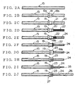
- FIGS.2A-2J are plan views sequentially showing the work process of the shielded wire by using the shielded wire processing apparatus;
- FIG.3 is an exploded perspective view showing a halfway state (a state of the braid being folded back) of the work process of the shielded wire;
- FIG.4 is a side view showing an embodiment of the inventive braid folding unit of the shielded wire;
- FIG.5 is a front view mainly showing a braid expanding means of the braid folding unit;
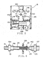
- FIG.6 is a partly sectional plan view showing a main portion (a portion of folding back the braid) of the braid folding unit; and
- FIG.7 is a side view showing a main portion of a shielding pipe inserting unit.
- Embodiment(s) of the present invention will now be described in further detail with' reference to the accompanying drawings. FIG.1 is a perspective view showing an embodiment of a shielded wire processing apparatus including the inventive braid folding unit of a shielded wire.
- This shielded wire processing apparatus 1 has, successively from the right, a
console 2 to change the article number, automatic/manual operation and so on, a wire setting unit 3, a shieldcontactor insertion unit 4, a sheath cutting unit 5, a sheath pulling outunit 6, a braid cutting unit 7, abraid folding unit 8, a shieldingpipe inserting unit 9, a shield pipe crimping unit 10, a stripping unit 11, aterminal crimping unit 12, a product picking-offunit 13, and a carryingunit 14 to shift the shieldedwire 15 along the units 3-13. A unit carrying out the braid folding and the shield pipe insertion is adopted in FIG.1, but thebraid folding unit 8 and the shieldingpipe inserting unit 9 may be arranged in parallel. The units 3-13 are arranged in parallel with almost the same intervals. - In FIG.1,
reference 16 denotes a hopper for feeding the shield contactor, and 17 denotes another hopper for feeding the shield pipe. The shieldedwire 15 can be thick up to a cross section of about 15mm2,which shieldedwire 15 is set on the wire setting unit 3 in a U-bent state or a straight state. - The shielded wire processing method and the action using the shielded wire processing apparatus 1 are described using FIGS. 1 and 2 hereinafter. First, an operator sets the shielded
wire 15 cut off in a determined length in advance as shown in FIG. 2A on the wire setting unit 3 of FIG.1. Only the setting of the wire has to be carried out by an operator. On setting the shieldedwire 15, thewire carrying unit 14 moves to the left by one pitch so as to send the shieldedwire 15 to the shieldcontactor insertion unit 4. - The
circular shield contactor 19 made of conductive metal is fitted on the shieldedwire 15 by the shieldcontactor insertion unit 4 as shown in FIG.2B. As also shown in FIG.3, theshield contactor 19 consists of a large-diameter collar portion 19a and a small-diameter tube portion 19b. The shieldedwire 15 having theshield contactor 19 is sent to the next sheath cutting unit 5 of the carryingunit 14. As shown in FIG.2C, at a determined position nearer the end side of the wire than theshield contactor 19 as shown in FIG.2C, acut 21 is provided circularly on an insulative sheath (outer cover) 20 of the shieldedwire 15. - Subsequently, the shielded
wire 15 is sent to the sheath pulling outunit 6, and theouter cover 20 is pulled out as shown in FIG.2D, whereby aninside metal braid 22. is exposed by the determined length. Thebraid 22 is made up of conductive thin metal wires braided crossingly as shown in FIG.3. Subsequently, the shieldedwire 15 is sent to the inventive braid cutting unit 7, and thebraid 22 exposed as shown in FIG.2E is cut off in the determined length, whereby an insulativeinner cover 24 is exposed. - Subsequently, the shielded
wire 15 is sent to the inventivebraid folding unit 8, and thebraid 22, as shown in FIG.2F, is folded back toward the small-diameter tube portion 19b of theshield contactor 19. Then, acircular shield pipe 23 made of conductive metal is fitted on the shieldedwire 15 from the end thereof by the shieldingpipe inserting unit 9 as shown in FIGS.2G and 3. Thebraid 22 is put between the inner surface of theshield pipe 23 and the outer surface of thetube portion 19b of theshield contactor 19 at a longitudinal determined position of the shieldedwire 15. A folding angle of thebraid 22 is between 90° and 180°. - Subsequently, the shielded
wire 15 is sent to the shield pipe crimping unit 10, theshield pipe 23 is crimped hexagonally so as to be fastened to theshield contactor 19 as shown in FIG.2H. Because thebraid 22 is put between theshield contactor 19 and theshield pipe 23, theshield pipe 23 and theshield contactor 19 are tightly fastened to the shieldedwire 15. - Subsequently, the shielded
wire 15 is sent to the stripping unit 11, the end side of theinner cover 24 of the shieldedwire 15 is stripped by a determined length as shown in FIG.2I, whereby the core wire (i.e. conductor portion) 25 is exposed. Subsequently, the shieldedwire 15 is sent to theterminal crimping unit 12, the terminal 26 is crimped to the exposedcore wire 25 as shown in FIG.2J. Finally, aproduct 27 is transferred from the processing apparatus 1 to an external pallet (not shown) by a product picking-offunit 13. Here, theterminal crimping unit 12 may be separated from the shielded wire processing apparatus 1. - Hereinafter, referring to FIGS.4-6, an embodiment of the inventive braid folding unit and method are described. In FIGS.4 and 5,
reference 134 is a braid expanding tooth, 135 is a braid expanding pipe, 19 is the shield contactor, 136 is a contactor pusher, and 137 is a braid folding member. - In FIG.4, the
wire 15 is held at the middle portion thereof by achuck 138, is supported ahead of the middle portion by thecontactor pusher 136, and is supported at the end portion thereof by the expandingpipe 135. Thecontactor pusher 136 consists of a right and left pair of chucks, which do not hold, but support, thewire 15, is opened or closed by a vertically installed air-operated opening-closing cylinder (opening-closing means) 139, and is movable forward and backward along a guide shaft (a guiding means) 141 of a horizontally installed air-operated cylinder (a driving means) 140. Thecontactor pusher 136 acts as a wire aligning (or positioning) member. Thechuck 138 is horizontally opened by an air-operatedchuck cylinder 130. Behind thechuck 138, another chuck (not shown) of the carrying unit 14 (FIG.1) is positioned. Thecontactor pusher 136 consists of a plate portion 136a being vertical and anupper base portion 136b being horizontal and is formed in a generally L-shape. A wire support hole 136c is formed on the vertical plate portion 136a. A bore diameter of the wire support hole 136c is smaller than the outside diameter of acollar portion 19a (FIG.3) of theshield contactor 19. The front surface of the plate portion 136a is abuttable on the rear end surface of thecollar portion 19a of theshield contactor 19. Here, the front side in this specification is defined as the end side of thewire 15. - The
base portion 136b is connected with the opening-closing cylinder 139 at a rearward position so as not to interfere with theshield contactor 19. The opening-closing cylinder 139 is connected to a rod 140a of a rearhorizontal cylinder 140 through a joint member. Thecylinder 140 is fixed to an upperhorizontal frame baseplate 129 by abracket 128. Thecylinder 139 slidably engages aguide shaft 141 by anupper bearing 127. - The
braid expanding pipe 135 shown in FIG.6 (a plan view) can be separated right and left and has a taperedslanting surface 142 at the end portion. The bore diameter of the expandingpipe 135 is a little large than the outside diameter of the inner cover of the shielded wire. The outside diameter of the expandingpipe 135 is desirably not less than the outside diameter of thetube portion 19b of theshield contactor 19. - The expanding
pipe 135 is connected to the air-operated opening-closing cylinder 143 (an opening-closing means) (FIG.4) and is openable-and-closable. The opening-closing cylinder 143 slidably engages an upperhorizontal guide shaft 141 through a bearing and is connected with a rod 144a of a horizontal air-operated cylinder (a driving means) 144 through a joint member so as to be movable in a wire's longitudinal direction. Thecylinder 144 is fixed to theupper frame baseplate 129 through thefront bracket 126. Thebraid folding member 137 is arranged slidably in the wire longitudinal direction with a gap to the outside of the expandingpipe 135. - The
braid folding member 137 is provided with a circular hole 137a on its vertical plate portion, which circular hole 137a can be symmetrically separated right and left. Thebraid folding member 137 is openably-and-closably connected to the opening-closing cylinder (an opening-closing means) 143 like a pair of chucks. The bore diameter of the circular hole 137a is almost equal to, or a little larger than, the outside diameter of thetube portion 19b of theshield contactor 19. - The opening-
closing cylinder 143 is connected to thehorizontal guide shaft 141 by anupper bearing 125. Theguide shaft 141 also acts as a drive shaft. A drive shaft may be arranged in parallel with theguide shaft 141. The drive shaft 141 (the same reference as that of theguide shaft 141 being used) is connected with arod 147 of a horizontal air-operated cylinder (a driving means) 146 and is movable in the wire longitudinal direction. Thecylinder 146 may be replace with a motor (not shown), theguide shaft 141 may be replace with a ball screw shaft (not shown), and thebearing 125 may be replace with a nut portion (not shown). - In FIG.4, a right and left pair of
braid expanding teeth 134 are positioned under thewire 15. In FIG.5, a braid primary expanding means 215 is shown. The right and left expandingteeth 134 are connected with a rod 148a of a horizontal floating air-operated cylinder (a driving means) 148 and a cylinder body (148 being also assigned), respectively, through respective slidingmembers horizontal rail 151. The right and left expandingteeth 134 are openable-and-closable in a wire's lateral direction by virtue of thecylinder 148. - The expanding
teeth 134 and thecylinder 148 are connected with a rod of a vertical air-operated cylinder (a driving means) 153 as shown in FIG.4 and are vertically movable. Thevertical air cylinder 153 is fixed to the lowerhorizontal baseplate 154. Thebaseplate 154 slidably engages a horizontal guide rail (a guiding means) 155 and is movable in the wire longitudinal direction by a horizontal air-operated cylinder (a driving means) 156. The expandingtooth 134 is semicircular and has a wedge being not so sharp. - Referring to FIG.4, the expanding
teeth 134 are lifted by means of thecylinder 153 in their opened state by means of thecylinder 148. Thebraid 22 of thewire 15 is positioned between the pair of expandingteeth 134. As shown in FIG.6 (a plan view), the expandingteeth 134 push thebraid 22 toward theinner cover 24 repeatedly so as to expand thebraid 22 in a bell-like shape. - By virtue of the
cylinder 148 as a driving means, thebraid 22 of the shieldedwire 15 can be repeatedly pressed by the expandingteeth 134 with an appropriate force, whereby thebraid 22 can be securely opened in a bell-like shape without any damage. - Subsequently, the
inner cover 24 is covered, but not held, by the expandingpipe 135 by closing the expandingpipe 135 by means of the opening-closing cylinder 143. The expandingpipe 135 is advanced toward thebraid 22 so that the slantingsurface 142 pushes an inner surface of the bell-like shaped portion of thebraid 22. thereby to further expand thebraid 22 outward. Here, by opening the expandingpipe 135 right and left by thecylinder 143, thebraid 22 can be further expanded outward. In this case, the foldingmember 137 has to be apart from the expandingpipe 135. - The
shield contactor 19 is pushed at the rear surface of thecollar portion 19a by the pushingmember 136 by virtue of thecylinder 140 and moves up to the front end position of theouter cover 20. The foldingmember 137 advances along the expandingpipe 135 by virtue of thecylinder 146 so that thebraid 22 is folded back over the outer surface of thetube portion 19b of thecontactor 19. At this time, the expandingteeth 134 is in an opened state by virtue of thecylinder 148 and also is at the lower position by virtue of thecylinder 153. The expandingteeth 134 can change its position in the wire longitudinal direction by virtue of thehorizontal cylinder 156 on the frame. - The
wire 15 with thebraid 22 having been folded back is then sent to the next shieldingpipe inserting unit 9 by the carryingunit 14. The outline of the shieldingpipe inserting unit 9 is shown in FIG.7. Theshield pipe 23 is a circular member and is fitted on the foldedbraid 22 on thetube portion 19b of theshield contactor 19 so as to secure thebraid 22 to theshield contactor 19. - As shown in FIG.7, the
shield pipe 23 is fitted on thewire 15 from its end by an axial movement of aparts transferring portion 42 driven by a cylinder (not shown). On this occasion, the end portion of thewire 15 is supported by the supportingmember 157 of an openable-closable chuck type and is aligned. Theparts transferring portion 42 pushes the supportingmember 157 along aguide shaft 158 in the wire longitudinal direction and fits theshield pipe 23 on thewire 15. At this time, the supportingmember 157 evades by separating right and left by virtue of the opening-closing cylinder 159. - The
shield contactor 19 is pushed by the pushingmember 160 of a chuck-type until theshield contactor 19 is put into contact with thebraid 22, and theparts transferring portion 42 advances so as to fit theshield pipe 23 on thebraid 22. Thebraid 22 is further folded backward on thetube portion 19b of theshield contactor 19. - The opening-
closing cylinder 159 of the supportingmember 157 is energized toward theparts transferring portion 42 by a coil spring (an energization member) 161 and is stopped while abutting against astopper 162. The pushingmember 160 is opened or closed by the opening-closing cylinder 163. The opening-closing cylinder 163 slidably engages thehorizontal guide shaft 158 and is connected with therod 165 of thehorizontal air cylinder 164 movably in the wire longitudinal direction. - The pushing
member 160 advances along thewire 15 by virtue of thecylinder 164 and positions theshield contactor 19 behind the foldedbraid 22. The pushingmember 160 is openable-and-closable and only supports, does not hold, thewire 15. The aligning of thewire 15 is securely carried out by the pushingmember 160 so that theshield pipe 23 can be securely fitted on the folded braid. Thewire 15 is held by thechuck 166 behind the pushingmember 160. - Here, the pushing
member 136 of FIG.4 may substitute for the pushingmember 136 of FIG.4, thecylinder 139 of FIG.4 may substitute for thechuck 166 of FIG.7, and thechuck 138 of FIG.4 may substitute for thechuck 166 of FIG.7. - When the
shield contactor 19 with a generally triangle collar portion (not shown) is used, the collar portion is set in a state that a peak of the collar portion is positioned downward and a right and left pair of positioning pins (not shown) are provided on the front surface of thecontactor pusher member 136 so that the collar portion can be predeterminedly directed by putting the collar portion between the pines. - Although the present invention has been fully described by way of examples with reference to the accompanying drawings, it is to be noted that various changes and modifications will be apparent to those skilled in the art. Therefore, unless otherwise such changes and modifications depart from the scope of the present invention, they should be construed as being included therein.
Claims (3)
- A braid folding unit of a shielded wire, comprising:a primary expanding means (215) to beat a braid (22) exposed on an inner cover (24) of the shielded wire (15) so as to outwardly expand the braid (22);an expanding pipe (135) to enter an inside of the braid (22) along the inner cover (24) so as to further outwardly expand the braid; wherein the expanding pipe (135) has an inner bore diameter which is larger than the outside diameter of the inner cover (24) and being openable and closable by an opening-closing means, and the braid (22) can be further expanded by opening the expanding pipe (135), anda braid folding member (137) formed to advance along an outside surface of the closed expanding pipe (135) so as to push the braid (22) in an axial direction of the shielded wire (15) and to fold back the braid (22) over the outer surface of a shield contactor (19) disposed on the shielded wire (15).
- The braid folding unit of the shielded wire as set forth in claim 1, wherein the primary expanding means (215) has a pair of openable-and-closable expanding teeth (134), a pair of sliding members fixing the respective expanding teeth (134), and a driving means to open and close the pair of sliding members in opposite directions.
- A braid folding method of a shielded wire, comprising the steps of:beating a braid (22) exposed on an inner cover (24) of the shielded wire (15) by a primary expanding means (215) so as to outwardly expand the braid (22);entering an expanding pipe (135) into an inside of the braid (22) along the inner cover(24) so as to further outwardly expand the braid (22) by an end sloping portion of the expanding pipe (135), wherein the braid (22) can be further outwardly expanded by opening the openable-and-closable expanding pipe (215); andadvancing a braid folding member (137) along an outside surface of the expanding pipe (135) so as to push the braid (22) in an axial direction of the shielded wire (15) and to fold back the braid (22) over the outer surface of a contactor (19) disposed on the shielded wire (15).
Applications Claiming Priority (2)
| Application Number | Priority Date | Filing Date | Title |
|---|---|---|---|
| JP2001058475A JP2002262429A (en) | 2001-03-02 | 2001-03-02 | Shield wire braiding device and braid folding method |
| JP2001058475 | 2001-03-02 |
Publications (3)
| Publication Number | Publication Date |
|---|---|
| EP1237237A2 EP1237237A2 (en) | 2002-09-04 |
| EP1237237A3 EP1237237A3 (en) | 2003-11-26 |
| EP1237237B1 true EP1237237B1 (en) | 2006-02-01 |
Family
ID=18918192
Family Applications (1)
| Application Number | Title | Priority Date | Filing Date |
|---|---|---|---|
| EP02004767A Expired - Lifetime EP1237237B1 (en) | 2001-03-02 | 2002-03-01 | Braid folding unit and a braid folding method of a shielded wire |
Country Status (4)
| Country | Link |
|---|---|
| US (1) | US6776196B2 (en) |
| EP (1) | EP1237237B1 (en) |
| JP (1) | JP2002262429A (en) |
| DE (1) | DE60208941T2 (en) |
Families Citing this family (25)
| Publication number | Priority date | Publication date | Assignee | Title |
|---|---|---|---|---|
| US7548477B2 (en) * | 2005-05-23 | 2009-06-16 | Infineon Technologies Flash Gmbh & Co. Kg | Method and apparatus for adapting circuit components of a memory module to changing operating conditions |
| DE102005024683B4 (en) * | 2005-05-30 | 2011-02-03 | Rosenberger Hochfrequenztechnik Gmbh & Co. Kg | Method of preparing a cable end for mounting a connector |
| JP4298709B2 (en) * | 2006-01-26 | 2009-07-22 | 矢崎総業株式会社 | Terminal processing method and terminal processing apparatus for shielded wire |
| US20090057376A1 (en) * | 2007-08-29 | 2009-03-05 | Honeywell International Inc. | Automated evacuation and sealing process |
| US8844602B2 (en) * | 2008-11-21 | 2014-09-30 | Sumitomo Electric Industries, Ltd. | Method of processing terminus of optical fiber and terminus processing tool |
| DE202009016970U1 (en) * | 2009-12-16 | 2011-04-28 | Huber + Suhner Ag | connecting device |
| JP5837739B2 (en) * | 2010-07-15 | 2015-12-24 | 矢崎総業株式会社 | Braided wire connection structure |
| JP5762219B2 (en) * | 2011-08-31 | 2015-08-12 | 矢崎総業株式会社 | Method of connecting braided shield layer of shielded wire and drain wire, and connection structure |
| DE202011105520U1 (en) * | 2011-09-09 | 2012-12-12 | Schäfer Werkzeug- und Sondermaschinenbau GmbH | crimper |
| JP5830354B2 (en) * | 2011-11-04 | 2015-12-09 | 矢崎総業株式会社 | Electric wire terminal processing jig and electric wire terminal processing method |
| JP5897980B2 (en) * | 2012-04-27 | 2016-04-06 | 矢崎総業株式会社 | Terminal processing method and terminal processing apparatus for coaxial cable |
| DE102012020798B3 (en) * | 2012-10-23 | 2014-04-10 | Rosenberger Hochfrequenztechnik Gmbh & Co. Kg | Apparatus and method for processing an end of a cable |
| US8991045B2 (en) * | 2013-03-12 | 2015-03-31 | Delphi Technologies, Inc. | Grounding arrangement and method for a shielded cable |
| EP2871736A1 (en) * | 2013-11-11 | 2015-05-13 | Schleuniger Holding AG | System for processing a multiple conductor cable |
| EP3021420B1 (en) * | 2014-11-12 | 2017-01-11 | MD Elektronik GmbH | Multi-core shielded cable and method for producing such a cable |
| DE102015009989A1 (en) | 2015-07-31 | 2017-02-02 | Komax SLE GmbH & Co. KG | Cable clamping device for widening screen braids of cables |
| CN111653923B (en) * | 2019-03-04 | 2025-08-05 | 泰科电子(上海)有限公司 | Metal foil expansion equipment |
| JP6929902B2 (en) * | 2019-06-28 | 2021-09-01 | 矢崎総業株式会社 | Braid folding device for the end of the coaxial wire |
| JP7181243B2 (en) * | 2020-02-06 | 2022-11-30 | 矢崎総業株式会社 | Braid folding device and braid folding method |
| JP7157100B2 (en) * | 2020-06-05 | 2022-10-19 | 矢崎総業株式会社 | Braid cuff cutting device and braid cuff cutting method |
| US12438347B2 (en) * | 2021-11-29 | 2025-10-07 | Aptiv Technologies AG | Method of cutting shielding conductor of a high voltage cable and apparatus to be used therefore |
| CN114871363A (en) * | 2022-04-02 | 2022-08-09 | 广东银钢智能科技有限公司 | Cable braid turning shielding net method and braid turning shielding net device |
| JP7787032B2 (en) * | 2022-07-27 | 2025-12-16 | 矢崎総業株式会社 | Wire end processing equipment |
| JP7754780B2 (en) * | 2022-07-27 | 2025-10-15 | 矢崎総業株式会社 | Wire end processing equipment |
| US20250385496A1 (en) * | 2024-06-17 | 2025-12-18 | Te Connectivity Solutions Gmbh | Method for Cable Braid Folding |
Family Cites Families (8)
| Publication number | Priority date | Publication date | Assignee | Title |
|---|---|---|---|---|
| US3621560A (en) | 1969-07-17 | 1971-11-23 | Bell Telephone Labor Inc | Method and apparatus for opening an end of a braided conductor of a coaxial cable |
| JPS5022712B1 (en) | 1969-09-04 | 1975-08-01 | ||
| US4719697A (en) | 1985-08-05 | 1988-01-19 | Amp Incorporated | Method of preparing coaxial cable for termination |
| DE4027904C2 (en) | 1990-09-03 | 1994-04-14 | Siemens Ag | Device for processing shielded electrical cables |
| US5595219A (en) * | 1994-12-01 | 1997-01-21 | The Whitaker Corporation | Apparatus and method for splaying the shield wires of a coaxial cable |
| JP2000032626A (en) | 1998-07-09 | 2000-01-28 | Yazaki Corp | Braid treatment method and braid treatment equipment for shielding wire |
| US6243947B1 (en) * | 1998-09-22 | 2001-06-12 | Sumitomo Wiring Systems, Ltd. | Method for processing an end of a shielded cable |
| US6536103B1 (en) * | 2000-08-24 | 2003-03-25 | Holland Electronics, Llc | Tool for installing a coaxial cable connector |
-
2001
- 2001-03-02 JP JP2001058475A patent/JP2002262429A/en not_active Abandoned
-
2002
- 2002-02-27 US US10/083,605 patent/US6776196B2/en not_active Expired - Fee Related
- 2002-03-01 EP EP02004767A patent/EP1237237B1/en not_active Expired - Lifetime
- 2002-03-01 DE DE60208941T patent/DE60208941T2/en not_active Expired - Lifetime
Also Published As
| Publication number | Publication date |
|---|---|
| JP2002262429A (en) | 2002-09-13 |
| EP1237237A2 (en) | 2002-09-04 |
| EP1237237A3 (en) | 2003-11-26 |
| DE60208941T2 (en) | 2006-09-21 |
| US20020121185A1 (en) | 2002-09-05 |
| DE60208941D1 (en) | 2006-04-13 |
| US6776196B2 (en) | 2004-08-17 |
Similar Documents
| Publication | Publication Date | Title |
|---|---|---|
| EP1237237B1 (en) | Braid folding unit and a braid folding method of a shielded wire | |
| CN104769796B (en) | For handling the device and method of the end of cable | |
| US5737835A (en) | Method and apparatus for manufacturing a wire crimping receptacle connector | |
| JP3908915B2 (en) | Braided cutting device for shielded wire and braided cutting method | |
| JPH09320347A (en) | Automotive wire harness and its manufacture | |
| US6883232B2 (en) | Apparatus for finishing stripped end of shield wire | |
| EP3163697B1 (en) | Separating a shielding of a coaxial cable | |
| US3555672A (en) | High speed semiautomatic termination of coaxial cable | |
| US6289573B1 (en) | Apparatus for making up a cable | |
| JP3039304B2 (en) | Terminal crimping equipment for shielded wires | |
| US7363693B2 (en) | Wire-processing device | |
| CN215184979U (en) | A accurate direction auxiliary device that is used for pencil terminal and connector to assemble | |
| JP2010277852A (en) | Terminal crimping apparatus and terminal crimping method | |
| JPS62105384A (en) | Manufacture of electric connector and apparatus for the same | |
| JP7374234B2 (en) | Magazine for processing wire-end ferrules and hand-held tool for crimping wire-end ferrules | |
| CN116565662A (en) | Manufacturing method of electric wire with terminal | |
| JPS63279586A (en) | Automatic apparatus for attaching connecting tool to end of conductor | |
| JP2769247B2 (en) | Manufacturing method of wire crimping harness | |
| WO2021241294A1 (en) | Terminal, and electric cable with terminal | |
| US4007534A (en) | Multi-conductor half tap | |
| EP4443678A1 (en) | Electrical wire stripping solution for automated splicing or welding | |
| EP4435983A1 (en) | Stripping tool for automated system, system and method | |
| US20250023313A1 (en) | Core wire alignment apparatus for multi-core cable | |
| CN218677937U (en) | Shielded wire turning-over device | |
| EP4589790A1 (en) | Member mounting device, electric wire processing device, and member mounting method |
Legal Events
| Date | Code | Title | Description |
|---|---|---|---|
| PUAI | Public reference made under article 153(3) epc to a published international application that has entered the european phase |
Free format text: ORIGINAL CODE: 0009012 |
|
| AK | Designated contracting states |
Kind code of ref document: A2 Designated state(s): AT BE CH CY DE DK ES FI FR GB GR IE IT LI LU MC NL PT SE TR |
|
| AX | Request for extension of the european patent |
Free format text: AL;LT;LV;MK;RO;SI |
|
| PUAL | Search report despatched |
Free format text: ORIGINAL CODE: 0009013 |
|
| AK | Designated contracting states |
Kind code of ref document: A3 Designated state(s): AT BE CH CY DE DK ES FI FR GB GR IE IT LI LU MC NL PT SE TR |
|
| AX | Request for extension of the european patent |
Extension state: AL LT LV MK RO SI |
|
| 17P | Request for examination filed |
Effective date: 20040510 |
|
| 17Q | First examination report despatched |
Effective date: 20040705 |
|
| AKX | Designation fees paid |
Designated state(s): CH DE FR LI |
|
| GRAC | Information related to communication of intention to grant a patent modified |
Free format text: ORIGINAL CODE: EPIDOSCIGR1 |
|
| GRAP | Despatch of communication of intention to grant a patent |
Free format text: ORIGINAL CODE: EPIDOSNIGR1 |
|
| GRAS | Grant fee paid |
Free format text: ORIGINAL CODE: EPIDOSNIGR3 |
|
| GRAA | (expected) grant |
Free format text: ORIGINAL CODE: 0009210 |
|
| RIN1 | Information on inventor provided before grant (corrected) |
Inventor name: YAMAKAWA, NOBUAKI, C/O YAZAKI PARTS CO., LTD. |
|
| AK | Designated contracting states |
Kind code of ref document: B1 Designated state(s): CH DE FR LI |
|
| REG | Reference to a national code |
Ref country code: CH Ref legal event code: EP |
|
| REF | Corresponds to: |
Ref document number: 60208941 Country of ref document: DE Date of ref document: 20060413 Kind code of ref document: P |
|
| REG | Reference to a national code |
Ref country code: CH Ref legal event code: NV Representative=s name: PATENTANWAELTE SCHAAD, BALASS, MENZL & PARTNER AG |
|
| ET | Fr: translation filed | ||
| PLBE | No opposition filed within time limit |
Free format text: ORIGINAL CODE: 0009261 |
|
| STAA | Information on the status of an ep patent application or granted ep patent |
Free format text: STATUS: NO OPPOSITION FILED WITHIN TIME LIMIT |
|
| 26N | No opposition filed |
Effective date: 20061103 |
|
| REG | Reference to a national code |
Ref country code: FR Ref legal event code: PLFP Year of fee payment: 14 |
|
| PGFP | Annual fee paid to national office [announced via postgrant information from national office to epo] |
Ref country code: CH Payment date: 20150313 Year of fee payment: 14 Ref country code: DE Payment date: 20150224 Year of fee payment: 14 |
|
| PGFP | Annual fee paid to national office [announced via postgrant information from national office to epo] |
Ref country code: FR Payment date: 20150309 Year of fee payment: 14 |
|
| REG | Reference to a national code |
Ref country code: DE Ref legal event code: R119 Ref document number: 60208941 Country of ref document: DE |
|
| REG | Reference to a national code |
Ref country code: CH Ref legal event code: PL |
|
| REG | Reference to a national code |
Ref country code: FR Ref legal event code: ST Effective date: 20161130 |
|
| PG25 | Lapsed in a contracting state [announced via postgrant information from national office to epo] |
Ref country code: DE Free format text: LAPSE BECAUSE OF NON-PAYMENT OF DUE FEES Effective date: 20161001 Ref country code: FR Free format text: LAPSE BECAUSE OF NON-PAYMENT OF DUE FEES Effective date: 20160331 Ref country code: LI Free format text: LAPSE BECAUSE OF NON-PAYMENT OF DUE FEES Effective date: 20160331 Ref country code: CH Free format text: LAPSE BECAUSE OF NON-PAYMENT OF DUE FEES Effective date: 20160331 |