EP1237223B1 - Filter apparatus, duplexer, and communication apparatus - Google Patents
Filter apparatus, duplexer, and communication apparatus Download PDFInfo
- Publication number
- EP1237223B1 EP1237223B1 EP02002584A EP02002584A EP1237223B1 EP 1237223 B1 EP1237223 B1 EP 1237223B1 EP 02002584 A EP02002584 A EP 02002584A EP 02002584 A EP02002584 A EP 02002584A EP 1237223 B1 EP1237223 B1 EP 1237223B1
- Authority
- EP
- European Patent Office
- Prior art keywords
- mode
- filter
- cavity
- dual
- resonator
- Prior art date
- Legal status (The legal status is an assumption and is not a legal conclusion. Google has not performed a legal analysis and makes no representation as to the accuracy of the status listed.)
- Expired - Lifetime
Links
- 238000004891 communication Methods 0.000 title claims description 17
- 230000005540 biological transmission Effects 0.000 claims description 27
- 230000000903 blocking effect Effects 0.000 claims description 2
- 238000010168 coupling process Methods 0.000 description 40
- 238000005859 coupling reaction Methods 0.000 description 40
- 230000008878 coupling Effects 0.000 description 32
- 239000004020 conductor Substances 0.000 description 13
- 230000005684 electric field Effects 0.000 description 12
- 239000013598 vector Substances 0.000 description 9
- 238000009826 distribution Methods 0.000 description 4
- 230000005672 electromagnetic field Effects 0.000 description 3
- 230000001413 cellular effect Effects 0.000 description 2
- 229910052751 metal Inorganic materials 0.000 description 2
- 239000002184 metal Substances 0.000 description 2
- BFTGQIQVUVTBJU-UHFFFAOYSA-N 5,6-dihydroimidazo[2,1-c][1,2,4]dithiazole-3-thione Chemical compound C1CN2C(=S)SSC2=N1 BFTGQIQVUVTBJU-UHFFFAOYSA-N 0.000 description 1
- 229910052782 aluminium Inorganic materials 0.000 description 1
- XAGFODPZIPBFFR-UHFFFAOYSA-N aluminium Chemical compound [Al] XAGFODPZIPBFFR-UHFFFAOYSA-N 0.000 description 1
- 239000000919 ceramic Substances 0.000 description 1
- 238000010586 diagram Methods 0.000 description 1
- 238000003780 insertion Methods 0.000 description 1
- 230000037431 insertion Effects 0.000 description 1
- 238000004519 manufacturing process Methods 0.000 description 1
- 239000000463 material Substances 0.000 description 1
- 238000010295 mobile communication Methods 0.000 description 1
- 238000000465 moulding Methods 0.000 description 1
- 239000011347 resin Substances 0.000 description 1
- 229920005989 resin Polymers 0.000 description 1
- 239000007787 solid Substances 0.000 description 1
Images


Classifications
-
- H—ELECTRICITY
- H01—ELECTRIC ELEMENTS
- H01P—WAVEGUIDES; RESONATORS, LINES, OR OTHER DEVICES OF THE WAVEGUIDE TYPE
- H01P1/00—Auxiliary devices
- H01P1/20—Frequency-selective devices, e.g. filters
- H01P1/207—Hollow waveguide filters
- H01P1/208—Cascaded cavities; Cascaded resonators inside a hollow waveguide structure
- H01P1/2084—Cascaded cavities; Cascaded resonators inside a hollow waveguide structure with dielectric resonators
- H01P1/2086—Cascaded cavities; Cascaded resonators inside a hollow waveguide structure with dielectric resonators multimode
-
- H—ELECTRICITY
- H01—ELECTRIC ELEMENTS
- H01P—WAVEGUIDES; RESONATORS, LINES, OR OTHER DEVICES OF THE WAVEGUIDE TYPE
- H01P1/00—Auxiliary devices
- H01P1/20—Frequency-selective devices, e.g. filters
- H01P1/213—Frequency-selective devices, e.g. filters combining or separating two or more different frequencies
- H01P1/2133—Frequency-selective devices, e.g. filters combining or separating two or more different frequencies using coaxial filters
Definitions
- the present invention relates to a filter apparatus having a plurality of resonators, a duplexer, and a communication apparatus, such as a base station communication apparatus.
- resonators used in the microwave band and capable of handling relatively large power include a cavity resonator and a semi-coaxial resonator.
- a semi-coaxial resonator is also known as a coaxial cavity resonator, and is relatively useful to form a compact filter etc. because of its relatively high Q factor and because it is more compact than a cavity resonator.
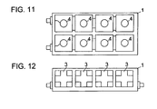
- Fig. 11 is a top view of a filter including semi-coaxial resonators, with a cavity lid removed.
- a filter having TM dual-mode dielectric resonators may also be useful to provide a compact resonator.
- Fig. 12 shows an example of a filter using TM dual-mode dielectric resonators.
- a cavity body 1 includes a cruciform dielectric core 3 in each resonator space so as to provide multiplexing of the two perpendicular TM modes.
- a filter apparatus having TM dual-mode resonators includes resonators formed of dielectric cores in all stages, and therefore may be compact as a whole; however, it requires a complicated manufacturing process for integral molding, thereby making it difficult to achieve cost-effectiveness.
- the present invention addresses the above problems by providing a compact and low-cost filter apparatus, a duplexer, and a communication apparatus incorporating these features.
- a filter apparatus includes a dual-mode resonator and a TEM single-mode resonator.
- the dual-mode resonator includes a conductive cavity that houses a conductive bar having at least one end electrically connected to the cavity and a dielectric core through which the bar is inserted.
- the dual-mode resonator duplexes and couples a TEM mode generated by the cavity and the bar and a TM mode generated by the cavity and the dielectric core.
- the TEM single-mode resonator includes a conductive cavity which houses a conductive bar having at least one end electrically connected to the cavity.
- a dual-mode, i.e., both TEM-mode and TM-mode, resonator may be used to achieve a compact filter apparatus.
- the dual-mode resonator is combined with a TEM single-mode resonator to construct a filter apparatus having a predetermined number of stages of resonators within a limited space at low cost.
- a duplexer in another aspect of the present invention, includes a reception filter and a transmission filter.
- the reception filter includes a plurality of dual-mode resonators as described above, wherein predetermined resonators between adjacent dual-mode resonators are coupled with each other.
- the transmission filter includes a dual-mode resonator and a TEM single-mode resonator, wherein predetermined resonators between adjacent resonators are coupled with each other.
- the duplexer further includes a shared input/output port which provides an input to the reception filter and an output from the transmission filter.
- a reception filter which generally requires a greater number of stages of resonators than a transmission filter is formed of a plurality of dual-mode resonators, and can therefore be reduced in size.
- a transmission filter includes a dual-mode resonator and a TEM single-mode resonator, and can thus provide the same resonator length in the alignment direction as that in the reception filter, while satisfying required frequency characteristics. Accordingly, a duplexer having such a reception filter and transmission filter can be made compact, in which the lengths of the resonators in the reception and transmission filters can be uniform in an alignment direction of the resonators. The duplexer can therefore be readily assembled into a communication device.
- the duplexer may further include a low-noise amplifier circuit for amplifying a reception signal output from the reception filter, wherein the low-noise amplifier circuit, the transmission filter, and the reception filter are housed by a housing. This provides a shorter distance from the reception filter to the low-noise amplifier circuit, thereby suppressing incoming noise, so that a reception signal having a high signal-to-noise ratio can be output from the duplexer.
- the duplexer may further include a low-pass filter between the shared input/output port and an antenna port, for transmitting a signal component in the transmission and reception frequency bands, and blocking a signal component in the frequency regions higher than the transmission and reception frequency bands. This can suppress emission of unwanted signals due to spurious modes.
- a communication apparatus such as a base station communication apparatus, includes the aforementioned duplexer, and a transmitter and a receiver which are connected to the duplexer.
- Abase station communication apparatus for example, can thus be made compact and cost-effective.
- Fig. 1 is a cross-sectional view of a dual-mode resonator.
- a cavity body 1 has an opening which is covered with a cavity lid 2.
- the cavity lid 2 includes a frequency-adjusting screw 16 in the center thereof for adjusting the resonant frequency by providing a predetermined gap length between the distal end of a conductive bar 4 and the inner surface of the cavity lid 2.
- Both lengthwise end surfaces of a dielectric core 3 are bonded to inner wall surfaces of the cavity body 1.
- the end surfaces of the dielectric core 3, which have been metalized with Ag electrodes, are soldered and bonded to the inner wall surfaces of the cavity body 1 so that the dielectric core 3 is positioned in the center of the cavity space.
- the cavity body 1 and the cavity lid2 areproducedbycastingorcuttingametalmaterial, orbydepositing a conductive film on a ceramic or resin member.
- a coupling-adjusting block 17 is installed in a predetermined position on the internal bottom surface of the cavity body 1.
- the coupling-adjusting block 17 may be integrally molded on the cavity body 1, or may be formed by screwing a rectangular metal block thereto.
- the coupling-adjusting block 17 allows the amount of coupling between a TEM mode and a TM mode, described later, to be adjusted.
- the dielectric core 3 has a coupling-adjusting hole h formed therein.
- a dielectric bar (not shown) can be externally inserted through the coupling-adjusting hole h, and, depending upon the amount of insertion, the amount of coupling between a TEM mode and a TM mode is adjusted.
- Figs. 2A to 2C show exemplary electromagnetic field distributions in the modes of the dual-mode resonator.
- solid arrows indicate electric field vectors
- broken arrows indicate magnetic field vectors.
- Fig. 2A is the electromagnetic field distribution in a TM mode generated by the dielectric core 3 and the cavity. In this mode, the electric field vectors are in the lengthwise direction of the dielectric core 3, and the magnetic vectors loop perpendicularly to the lengthwise direction of the dielectric core 3.
- the dielectric core 3 is rectangular, a cylindrical coordinate system is used herein for mode notation, and the number of waves in the electric field strength distribution is expressed as TM ⁇ rh, where value h is in the propagation direction, value r is in the in-plane radial direction perpendicular to the propagation direction, and value ⁇ is in the in-plane circumferential direction perpendicular to the propagation direction.
- the mode shown in Fig. 2A can thus be expressed as a TM010 mode, but this mode is different from a standard TM010 mode.
- this mode is a quasi TM010 mode.
- Fig. 2B is a top view of a semi-coaxial resonator formed of a cavity and a conductive bar
- Fig. 2C is a front view of the semi-coaxial resonator shown in Fig. 2B.
- This mode is a TEM mode in which the electric field vectors are directed in the radial direction from the conductive bar towards the inner wall surfaces of the cavity, while the magnetic field vectors loop in the circumferential direction about the conductive bar.
- the semi-coaxial resonator shown in Figs. 2B and 2C is loaded by the dielectric core 3, and a gap exists between the top of the conductive bar 4 and the upper surface of the cavity. Therefore, this mode is a quasi semi-coaxial resonator mode.
- the resonator parts shown in Fig. 1 are appropriately sized so that the resonator can be used as a 2 GHz band resonator having a TM mode resonant frequency of 1910 MHz and a TEM mode resonant frequency of 2155 MHz.
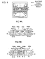
- Fig. 3 is a top view of an example of a mechanism for coupling the two modes with each other, showing the cavity body 1 after removal of the cavity lid 2.
- the TEM-mode electric field vectors E TEM are directed in the radial direction from the conductive bar 4, and the TM-mode electric field vectors E TM are directed along the dielectric core 3.
- the electric field strength from one lengthwise end of the dielectric core 3 to the center portion (the conductive bar 4) and the electric field strength from the other end of the dielectric core 3 to the center portion are made unbalanced.
- a coupling-adjusting hole h shown in Fig. 3 is provided, thereby causing the electric field strengths in the vicinity thereof to be asymmetrical.
- the amount of coupling depends upon the size (inner diameter or depth) of the coupling-adjusting hole h, or the amount by which a dielectric bar (not shown) is inserted into the coupling-adjusting hole h.
- a gap exists between the hole in the center of the dielectric core 3 and the conductive bar 4, thereby suppressing conductor loss due to current flowing in the conductive bar 4 and increasing the Q factor of the resonator.
- This gap is not essential, and, in some embodiments, a hole formed in the dielectric core may be engaged with a conductive bar.
- Figs. 4A and 4B are top views of two types of filter apparatuses, from which cavity lids have been removed.
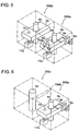
- Fig. 5 is a perspective view of the structure of resonators RWa and RWb shown in Fig. 4B.
- Fig. 6 is a perspective view of the structure of resonators RWa and RSb shown in Fig. 4A.
- cavity spaces are indicated by two-dot chain lines.
- An aluminum cavity body 1 is partitioned into four sections, by way of example. Cylindrical conductive bars 4a, 4b, 4c, and 4d are integrally formed on the cavity body 1. Each of the conductive bars 4a, 4b, 4c, and 4d make up a TEM mode resonator together with the cavity. In Figs. 4A and 4B, each of a plurality of substantially rectangular dielectric cores 3a, 3b, 3c, and 3d makes up a TM mode resonator together with the cavity.
- the resonators RWa and RWb are dual-mode resonators, and the resonators RSb and RSC are TEM single-mode resonators .
- Coupling loops 9a and 9d have first ends bonded to the inner wall surface of the cavity body 1, and second ends connected to the central conductors of coaxial connectors 8a and 8d, respectively.
- Coupling windows 15ab, 15bc, and 15cd are provided at the boundaries between the adjacent cavity spaces.
- the coupling loop 9a is coupled with a TM mode generated by the dielectric core 3a, and this TM mode is coupled with a TEM mode generated by the conductive bar 4a.
- This TEM mode is coupled with a TEM mode generated by the conductive bar 4b via the coupling window 15ab.
- This TEM mode is further coupled with a TEM mode generated by the conductive bar 4c via the coupling window 15bc.
- This TEM mode is coupled with a TEM mode generated by the conductive bar 4d via the coupling window 15cd.
- This TEM mode is coupled with a TM mode generated by the dielectric core 3d.
- the coupling loop 9d is coupled with this TM mode.
- a filter In Fig. 4B, dual-mode resonators RWa, RWb, and RWc, and a TEM single-mode resonator RSd, that is, a total of seven stages of resonators, form a filter.
- the coupling loop 9a is coupled with a TM mode generated by the dielectric core 3a, and this TM mode is coupled with a TEM mode generated by the conductive bar 4a.
- This TEM mode is coupled with a TEM mode generated by the conductive bar 4b via a coupling loop 10ab.
- This TEM mode is coupled with a TM mode generated by the dielectric core 3b.
- This TM mode is coupled with a TM mode generated by the dielectric core 3c via a coupling loop 10bc.
- This TMmode is coupled with a TEM mode generated by the conductive bar 4c.
- This TEM mode is coupled with a TEM mode generated by the conductive bar 4d via the coupling window 15cd.
- the coupling loop 9d connects the conductive bar 4d to the central conductor of the coaxial connector 8d. Therefore, the coupling loop 9d is coupled with the TEM mode generated by the conductive bar 4d.
- the coupling loop 10ab is not coupled with either the TM mode generated by the dielectric core 3a or the TM mode generated by the dielectric core 3b, and these two TM modes are not directly coupled with each other.
- the coupling loop 10bc is not coupled with either the TEM mode generated by the conductive bar 4b or the TEM mode generated by the conductive bar 4c, and these two TEM modes are not directly coupled with each other.
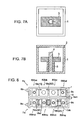
- Fig. 7A is a top view of a filter apparatus according to a second embodiment of the present invention with a cavity lid removed
- Fig. 7B is a longitudinal cross-sectional view of the filter apparatus.
- the end surfaces of the dielectric core 3 are spaced apart from the inner wall surfaces of the cavity.
- a support 5 for supporting the dielectric core 3 is a tube made of a material having a low dielectric constant, and is bonded to the dielectric core 3.
- the conductive bar 4 is inserted through the dielectric core 3 to which the support 5 is attached, whereby the dielectric core 3 is fixed in substantially the center of the cavity.
- the electric field strength also varies in the propagation direction, so that this resonant mode can be expressed as the TM01 ⁇ mode, where ⁇ is a number less than 1, meaning that although complete waves are not carried in the propagation direction, the strength varies.
- electrostatic capacitance is generated in the gaps between the end surfaces of the dielectric core 3 and the inner wall surfaces of the cavity, thereby reducing the electrostatic capacitance between the two inner wall surfaces of the cavity which face the lengthwise end surfaces of the dielectric core 3.
- This introduces an increase in the size of the cavity (distance between the facing inner wall surfaces of the cavity) in order to obtain the required resonant frequency in a TM mode.
- the current density of the current flowing in the cavity is reduced, thereby increasing the Q factor of the resonator.
- a transmission filter Ftx includes dual-mode resonators RWtxa and RWtxd, and TEM single-mode resonators RStxb and RStxc.
- a reception filter Frx includes dual-mode resonators RWrxa, RWrxb, RWrxc, and RWrxd.
- the duplexer further includes a coaxial connector 8tx for inputting a transmission signal, a coaxial connector 8ant for connecting an antenna cable, and a coaxial connector 8rx for outputting a reception signal.
- a TEM mode of the dual-mode resonator RWrxc is coupled with a TEM mode of the dual-mode resonator RWrxd via a coupling loop 10cd.
- a coupling loop 9rx is coupled to a TM mode of the dual-mode resonator RWrxa.
- a coupling loop 9tx is coupled to a TM mode of the dual-mode resonator RWtxd.
- a combining conductor 18 connects first ends of the coupling loops 9tx and 9rx with each other, and combines a transmission signal with a reception signal with a predetermined phase to connect the resulting signal to the central conductor of the antenna coaxial connector 8ant.
- a skip-coupling conductor 19rx(24) provides magnetic field coupling into a TEM mode of the dual-mode resonator RWrxa, and magnetic field coupling into a TM mode of the dual-mode resonator RWrxb.
- the skip-coupling conductor 19rx(24) enables the resonators at the second and fourth stages in the reception filter Frx to be coupled with each other.
- a skip-coupling conductor 19rx(57) provides magnetic field coupling into a TEM mode of the dual-mode resonator RWrxd, and magnetic field coupling into a TM mode of the dual-mode resonator RWrxc.
- the skip-coupling conductor 19rx(57) enables the resonators at the fifth and seventh stages in the reception filter Frx to be coupled with each other. In this way, resonators are coupled every other stage, and the polarity of the coupling is selected, thereby yielding a large attenuation in the vicinity of the reception band.
- a skip-coupling conductor 19tx (13) allows a TM mode of the dual-mode resonator RWtxa to be coupled with a TEM mode of the TEM single-mode resonator RStxb.
- the resonators at the first and third stages are thus coupled with each other, thereby yielding a large attenuation around the reception band in the transmission filter Ftx.
- a skip-coupling conductor 19tx(367) allows a TM mode of the TEM single-mode resonator RStxb to be coupled with a TM mode of the dual-mode resonator RWtxd, and further with the coupling loop 9tx.
- the skip-coupling conductor 19tx(367) enables the resonators at the third and sixth stages to be coupled with each other. At the same time, it allows the resonator at the third stage and the output coupling loop at the seventh stage to be coupled with each other. In this way, the resonators at the third and sixth stages are coupled with each other, and the resonator at the third stage and the output coupling loop are coupled with each other. This yields a large attenuation in the vicinity of the high frequency region and in the vicinity of the low frequency region of the transmission band.
- skip-coupling conductors may be provided at predetermined positions in order to readily couple predetermined resonators in a plurality of stages of resonators with each other.
- a communication apparatus according to a fourth embodiment of the present invention is now described with reference to Figs. 9 and 10.
- the described apparatus is a base station in this example, but the invention is equally applicable to a portable communication apparatus.
- Fig. 9 illustrates a connection relationship between the components
- Fig. 10 is an exploded perspective view of the overall apparatus.
- a coaxial connector for connection to an antenna cable is indicated by ANT
- a coaxial connector to be connected to a transmitter is indicated by TX
- a coaxial connector to be connected to a receiver is indicated by RX.
- a coaxial connector for connection to another space-diversity antenna cable is indicated by Div.ANT.
- the communication apparatus includes low-pass filters LPF which transmit signal components in the transmission and reception frequency bands and which block signal components in the frequency regions higher than the transmission and reception frequency bands.
- the two low-pass filters LPF are distributed-constant-type coaxial line filters.
- a duplexer DPX is the same type as that shown in Fig.
- the communication apparatus further includes a band-pass filter GGF, if necessary or desirable, which transmits a signal component in the transmission frequency band.
- a signal transmitted through the band-pass filter GGF is output through the Div.TX terminal. More specifically, radio waves emitted from an antenna (not shown) connected to the coaxial connector ANT are directly received by another space-diversity antenna (not shown) which is connected to the terminal Div.ANT.
- the received signal is passed through the low-pass filter LPF and the band-pass filter GGF, and is then output from the Div.TX terminal. The output signal is used to monitor the transmission signal.
- the communication apparatus further includes low-noise amplifier circuits LNA which amplify the output signal from the reception filter Frx in the duplexer DPX and the reception signal from the space-diversity reception filter BPF, respectively, at a predetermined gain.
- the amplified signals are distributed into four routes, which are then output from the corresponding coaxial connectors.
- a chassis 20 houses the two low-noise amplifier circuits LNA installed therein, and an intermediate plate 22 on which the two low-pass filters LPF, the duplexer DPX, and the space-diversity reception filter BPF are seated.
- a front plate 23 is attached to the side opening of the chassis 20, and the chassis 20 is covered by a lid 21, thus constructing the base station communication apparatus.
- the output connectors for the reception filter Frx in the duplexer DPX and for the space-diversity reception filter BPF are directly connected to the coaxial connectors of the low-noise amplifier circuits LNA through cutout portions of the intermediate plate 22.
- An output signal from each of the low-noise amplifier circuits LNA is led by four coaxial connectors to be output from the front plate 23.
Landscapes
- Control Of Motors That Do Not Use Commutators (AREA)
Description
- The present invention relates to a filter apparatus having a plurality of resonators, a duplexer, and a communication apparatus, such as a base station communication apparatus.
- In the related art, resonators used in the microwave band and capable of handling relatively large power include a cavity resonator and a semi-coaxial resonator. A semi-coaxial resonator is also known as a coaxial cavity resonator, and is relatively useful to form a compact filter etc. because of its relatively high Q factor and because it is more compact than a cavity resonator.
- Fig. 11 is a top view of a filter including semi-coaxial resonators, with a cavity lid removed. A
cavity body 1 having an opening, which is covered by a cavity lid, includes cylindricalconductive bars 4 in the centers of the cavities of the resonators in order to form a plurality of semi-coaxial resonators. Adjacent resonators are coupled to each other by known arrangements. - A filter having TM dual-mode dielectric resonators may also be useful to provide a compact resonator.
- Fig. 12 shows an example of a filter using TM dual-mode dielectric resonators. In Fig. 12, a
cavity body 1 includes a cruciformdielectric core 3 in each resonator space so as to provide multiplexing of the two perpendicular TM modes. - Document US-A-4271399 describes a resonator comprising a dielectric ring with a metal rod inserted in the hollow part of the dielectric member, supporting a hybrid TEM and TE10g mode.
- With the advent of micro-cell cellular mobile communication systems such as cellular phones, the demand for more compact filters in base stations has increased. In addition, as the number of installed filters has increased, more cost-effective filters have been increasingly required.
- However, a filter having semi-coaxial resonators still requires a large volume for each resonator, and thus the overall filter apparatus cannot be reduced in size. A filter apparatus having TM dual-mode resonators includes resonators formed of dielectric cores in all stages, and therefore may be compact as a whole; however, it requires a complicated manufacturing process for integral molding, thereby making it difficult to achieve cost-effectiveness.
- Accordingly, the present invention addresses the above problems by providing a compact and low-cost filter apparatus, a duplexer, and a communication apparatus incorporating these features.
- To this end, in a first aspect of the present invention, a filter apparatus includes a dual-mode resonator and a TEM single-mode resonator. The dual-mode resonator includes a conductive cavity that houses a conductive bar having at least one end electrically connected to the cavity and a dielectric core through which the bar is inserted. The dual-mode resonator duplexes and couples a TEM mode generated by the cavity and the bar and a TM mode generated by the cavity and the dielectric core. The TEM single-mode resonator includes a conductive cavity which houses a conductive bar having at least one end electrically connected to the cavity.
- A dual-mode, i.e., both TEM-mode and TM-mode, resonator may be used to achieve a compact filter apparatus. In addition, the dual-mode resonator is combined with a TEM single-mode resonator to construct a filter apparatus having a predetermined number of stages of resonators within a limited space at low cost.
- In another aspect of the present invention, a duplexer includes a reception filter and a transmission filter. The reception filter includes a plurality of dual-mode resonators as described above, wherein predetermined resonators between adjacent dual-mode resonators are coupled with each other. The transmission filter includes a dual-mode resonator and a TEM single-mode resonator, wherein predetermined resonators between adjacent resonators are coupled with each other. The duplexer further includes a shared input/output port which provides an input to the reception filter and an output from the transmission filter.
- A reception filter which generally requires a greater number of stages of resonators than a transmission filter is formed of a plurality of dual-mode resonators, and can therefore be reduced in size. A transmission filter includes a dual-mode resonator and a TEM single-mode resonator, and can thus provide the same resonator length in the alignment direction as that in the reception filter, while satisfying required frequency characteristics. Accordingly, a duplexer having such a reception filter and transmission filter can be made compact, in which the lengths of the resonators in the reception and transmission filters can be uniform in an alignment direction of the resonators. The duplexer can therefore be readily assembled into a communication device.
- The duplexer may further include a low-noise amplifier circuit for amplifying a reception signal output from the reception filter, wherein the low-noise amplifier circuit, the transmission filter, and the reception filter are housed by a housing. This provides a shorter distance from the reception filter to the low-noise amplifier circuit, thereby suppressing incoming noise, so that a reception signal having a high signal-to-noise ratio can be output from the duplexer.
- The duplexer may further include a low-pass filter between the shared input/output port and an antenna port, for transmitting a signal component in the transmission and reception frequency bands, and blocking a signal component in the frequency regions higher than the transmission and reception frequency bands. This can suppress emission of unwanted signals due to spurious modes.
- In still another aspect of the present invention, a communication apparatus, such as a base station communication apparatus, includes the aforementioned duplexer, and a transmitter and a receiver which are connected to the duplexer. Abase station communication apparatus, for example, can thus be made compact and cost-effective.
- Other features and advantages of the present invention will become apparent from the following description of embodiments of the invention which refers to the accompanying drawings.
- Fig. 1 is a cross-sectional view of a dual-mode resonator in a filter apparatus according to a first embodiment of the present invention;
- Figs. 2A to 2C are exemplary electromagnetic field distributions in resonant modes of the dual-mode resonator in the filter apparatus shown in Fig. 1;
- Fig. 3 is a top view showing that the two resonant modes of the dual-mode resonator are coupled with each other;
- Figs. 4A and 4B are top views of two implementations of the filter apparatus according to the first embodiment;
- Fig. 5 is a perspective view of the structure of two dual-mode resonators which are coupled with each other;
- Fig. 6 is a perspective view of the structure of a dual-mode resonator and a TEM single-mode resonator which are coupled with each other;
- Figs. 7A and 7B are a top view and a longitudinal cross-sectional view of a dual-mode resonator, respectively, according to a second embodiment of the present invention;
- Fig. 8 is a cross-sectional view of a duplexer according to a third embodiment of the present invention;
- Fig. 9 is a block diagram of a base station communication apparatus according to a fourth embodiment of the present invention;
- Fig. 10 is an exploded perspective view of the base station communication apparatus shown in Fig. 9;
- Fig. 11 is a structural view of a conventional filter apparatus; and
- Fig. 12 is a structural view of another conventional filter apparatus.
-
- The structure of a filter apparatus according to a first embodiment of the present invention is now described with reference to Figs. 1 to 6.
- Fig. 1 is a cross-sectional view of a dual-mode resonator. In Fig. 1, a
cavity body 1 has an opening which is covered with acavity lid 2. Thecavity lid 2 includes a frequency-adjustingscrew 16 in the center thereof for adjusting the resonant frequency by providing a predetermined gap length between the distal end of aconductive bar 4 and the inner surface of thecavity lid 2. - Both lengthwise end surfaces of a
dielectric core 3 are bonded to inner wall surfaces of thecavity body 1. For example, the end surfaces of thedielectric core 3, which have been metalized with Ag electrodes, are soldered and bonded to the inner wall surfaces of thecavity body 1 so that thedielectric core 3 is positioned in the center of the cavity space. Thecavity body 1 and the cavity lid2areproducedbycastingorcuttingametalmaterial, orbydepositing a conductive film on a ceramic or resin member. - A coupling-adjusting
block 17 is installed in a predetermined position on the internal bottom surface of thecavity body 1. The coupling-adjustingblock 17 may be integrally molded on thecavity body 1, or may be formed by screwing a rectangular metal block thereto. The coupling-adjustingblock 17 allows the amount of coupling between a TEM mode and a TM mode, described later, to be adjusted. Thedielectric core 3 has a coupling-adjusting hole h formed therein. A dielectric bar (not shown) can be externally inserted through the coupling-adjusting hole h, and, depending upon the amount of insertion, the amount of coupling between a TEM mode and a TM mode is adjusted. - Figs. 2A to 2C show exemplary electromagnetic field distributions in the modes of the dual-mode resonator. In Figs. 2A to 2C, solid arrows indicate electric field vectors, and broken arrows indicate magnetic field vectors. Fig. 2A is the electromagnetic field distribution in a TM mode generated by the
dielectric core 3 and the cavity. In this mode, the electric field vectors are in the lengthwise direction of thedielectric core 3, and the magnetic vectors loop perpendicularly to the lengthwise direction of thedielectric core 3. Although thedielectric core 3 is rectangular, a cylindrical coordinate system is used herein for mode notation, and the number of waves in the electric field strength distribution is expressed as TMrh, where value h is in the propagation direction, value r is in the in-plane radial direction perpendicular to the propagation direction, and value is in the in-plane circumferential direction perpendicular to the propagation direction. The mode shown in Fig. 2A can thus be expressed as a TM010 mode, but this mode is different from a standard TM010 mode. In this example, since thedielectric core 3 is not cylindrical, and theconductive bar 4 is located in the center of thedielectric core 3, this mode is a quasi TM010 mode. - Fig. 2B is a top view of a semi-coaxial resonator formed of a cavity and a conductive bar, and Fig. 2C is a front view of the semi-coaxial resonator shown in Fig. 2B. This mode is a TEM mode in which the electric field vectors are directed in the radial direction from the conductive bar towards the inner wall surfaces of the cavity, while the magnetic field vectors loop in the circumferential direction about the conductive bar. However, unlike a standard semi-coaxial resonator, the semi-coaxial resonator shown in Figs. 2B and 2C is loaded by the
dielectric core 3, and a gap exists between the top of theconductive bar 4 and the upper surface of the cavity. Therefore, this mode is a quasi semi-coaxial resonator mode. - The resonator parts shown in Fig. 1 are appropriately sized so that the resonator can be used as a 2 GHz band resonator having a TM mode resonant frequency of 1910 MHz and a TEM mode resonant frequency of 2155 MHz.
- In Figs. 2A to 2C, since the strengths of the electric field vectors in the lengthwise direction of the
dielectric core 3 are balanced in the TM mode and the TEM mode, these modes are not coupled with each other, if unchanged. Therefore, the electric field strengths in the two modes are made unbalanced, so that the two modes are coupled with each other. - Fig. 3 is a top view of an example of a mechanism for coupling the two modes with each other, showing the
cavity body 1 after removal of thecavity lid 2. The TEM-mode electric field vectors ETEM are directed in the radial direction from theconductive bar 4, and the TM-mode electric field vectors ETM are directed along thedielectric core 3. In order to couple the two modes with each other, the electric field strength from one lengthwise end of thedielectric core 3 to the center portion (the conductive bar 4) and the electric field strength from the other end of thedielectric core 3 to the center portion are made unbalanced. For this purpose, a coupling-adjusting hole h shown in Fig. 3 is provided, thereby causing the electric field strengths in the vicinity thereof to be asymmetrical. This results in coupling of the TEM mode and the TM mode. The amount of coupling depends upon the size (inner diameter or depth) of the coupling-adjusting hole h, or the amount by which a dielectric bar (not shown) is inserted into the coupling-adjusting hole h. - According to the first embodiment, a gap exists between the hole in the center of the
dielectric core 3 and theconductive bar 4, thereby suppressing conductor loss due to current flowing in theconductive bar 4 and increasing the Q factor of the resonator. This gap is not essential, and, in some embodiments, a hole formed in the dielectric core may be engaged with a conductive bar. - Figs. 4A and 4B are top views of two types of filter apparatuses, from which cavity lids have been removed. Fig. 5 is a perspective view of the structure of resonators RWa and RWb shown in Fig. 4B. Fig. 6 is a perspective view of the structure of resonators RWa and RSb shown in Fig. 4A. In Figs. 5 and 6, cavity spaces are indicated by two-dot chain lines.
- An
aluminum cavity body 1 is partitioned into four sections, by way of example. Cylindricalconductive bars cavity body 1. Each of theconductive bars dielectric cores - In Fig. 4A, the resonators RWa and RWb are dual-mode resonators, and the resonators RSb and RSC are TEM single-mode resonators . Coupling
loops cavity body 1, and second ends connected to the central conductors ofcoaxial connectors - The
coupling loop 9a is coupled with a TM mode generated by thedielectric core 3a, and this TM mode is coupled with a TEM mode generated by theconductive bar 4a. This TEM mode is coupled with a TEM mode generated by theconductive bar 4b via the coupling window 15ab. This TEM mode is further coupled with a TEM mode generated by theconductive bar 4c via the coupling window 15bc. This TEM mode is coupled with a TEM mode generated by theconductive bar 4d via the coupling window 15cd. This TEM mode is coupled with a TM mode generated by thedielectric core 3d. Thecoupling loop 9d is coupled with this TM mode. Eventually, with the structure shown in Fig. 4A, the two dual-mode resonators and the two TEM single-mode resonators, that is, a total of six stages of resonators, are in turn coupled with each other, and act as a filter having a band-pass characteristic. - In Fig. 4B, dual-mode resonators RWa, RWb, and RWc, and a TEM single-mode resonator RSd, that is, a total of seven stages of resonators, form a filter. Specifically, the
coupling loop 9a is coupled with a TM mode generated by thedielectric core 3a, and this TM mode is coupled with a TEM mode generated by theconductive bar 4a. This TEM mode is coupled with a TEM mode generated by theconductive bar 4b via a coupling loop 10ab. This TEM mode is coupled with a TM mode generated by thedielectric core 3b. This TM mode is coupled with a TM mode generated by thedielectric core 3c via a coupling loop 10bc. This TMmode is coupled with a TEM mode generated by theconductive bar 4c. This TEM mode is coupled with a TEM mode generated by theconductive bar 4d via the coupling window 15cd. Thecoupling loop 9d connects theconductive bar 4d to the central conductor of thecoaxial connector 8d. Therefore, thecoupling loop 9d is coupled with the TEM mode generated by theconductive bar 4d. - The coupling loop 10ab is not coupled with either the TM mode generated by the
dielectric core 3a or the TM mode generated by thedielectric core 3b, and these two TM modes are not directly coupled with each other. The coupling loop 10bc is not coupled with either the TEM mode generated by theconductive bar 4b or the TEM mode generated by theconductive bar 4c, and these two TEM modes are not directly coupled with each other. - Fig. 7A is a top view of a filter apparatus according to a second embodiment of the present invention with a cavity lid removed, and Fig. 7B is a longitudinal cross-sectional view of the filter apparatus. In the second embodiment, the end surfaces of the
dielectric core 3 are spaced apart from the inner wall surfaces of the cavity. In Fig. 7B, asupport 5 for supporting thedielectric core 3 is a tube made of a material having a low dielectric constant, and is bonded to thedielectric core 3. Theconductive bar 4 is inserted through thedielectric core 3 to which thesupport 5 is attached, whereby thedielectric core 3 is fixed in substantially the center of the cavity. - If gaps exist between the lengthwise end surfaces of the
dielectric core 3 and the inner wall surfaces of the cavity, the electric field strength also varies in the propagation direction, so that this resonant mode can be expressed as the TM01δ mode, where δ is a number less than 1, meaning that although complete waves are not carried in the propagation direction, the strength varies. - With this structure, electrostatic capacitance is generated in the gaps between the end surfaces of the
dielectric core 3 and the inner wall surfaces of the cavity, thereby reducing the electrostatic capacitance between the two inner wall surfaces of the cavity which face the lengthwise end surfaces of thedielectric core 3. This introduces an increase in the size of the cavity (distance between the facing inner wall surfaces of the cavity) in order to obtain the required resonant frequency in a TM mode. However, the current density of the current flowing in the cavity is reduced, thereby increasing the Q factor of the resonator. - The structure of a duplexer according to a third embodiment of the present invention is now described with reference to Fig. 8.
- In Fig. 8, a transmission filter Ftx includes dual-mode resonators RWtxa and RWtxd, and TEM single-mode resonators RStxb and RStxc. A reception filter Frx includes dual-mode resonators RWrxa, RWrxb, RWrxc, and RWrxd. The duplexer further includes a coaxial connector 8tx for inputting a transmission signal, a coaxial connector 8ant for connecting an antenna cable, and a coaxial connector 8rx for outputting a reception signal.
- A TEM mode of the dual-mode resonator RWrxc is coupled with a TEM mode of the dual-mode resonator RWrxd via a coupling loop 10cd. A coupling loop 9rx is coupled to a TM mode of the dual-mode resonator RWrxa. A coupling loop 9tx is coupled to a TM mode of the dual-mode resonator RWtxd. A combining
conductor 18 connects first ends of the coupling loops 9tx and 9rx with each other, and combines a transmission signal with a reception signal with a predetermined phase to connect the resulting signal to the central conductor of the antenna coaxial connector 8ant. - In Fig. 8, a skip-coupling conductor 19rx(24) provides magnetic field coupling into a TEM mode of the dual-mode resonator RWrxa, and magnetic field coupling into a TM mode of the dual-mode resonator RWrxb. The skip-coupling conductor 19rx(24) enables the resonators at the second and fourth stages in the reception filter Frx to be coupled with each other. A skip-coupling conductor 19rx(57) provides magnetic field coupling into a TEM mode of the dual-mode resonator RWrxd, and magnetic field coupling into a TM mode of the dual-mode resonator RWrxc. The skip-coupling conductor 19rx(57) enables the resonators at the fifth and seventh stages in the reception filter Frx to be coupled with each other. In this way, resonators are coupled every other stage, and the polarity of the coupling is selected, thereby yielding a large attenuation in the vicinity of the reception band.
- A skip-coupling conductor 19tx (13) allows a TM mode of the dual-mode resonator RWtxa to be coupled with a TEM mode of the TEM single-mode resonator RStxb. The resonators at the first and third stages are thus coupled with each other, thereby yielding a large attenuation around the reception band in the transmission filter Ftx.
- A skip-coupling conductor 19tx(367) allows a TM mode of the TEM single-mode resonator RStxb to be coupled with a TM mode of the dual-mode resonator RWtxd, and further with the coupling loop 9tx. The skip-coupling conductor 19tx(367) enables the resonators at the third and sixth stages to be coupled with each other. At the same time, it allows the resonator at the third stage and the output coupling loop at the seventh stage to be coupled with each other. In this way, the resonators at the third and sixth stages are coupled with each other, and the resonator at the third stage and the output coupling loop are coupled with each other. This yields a large attenuation in the vicinity of the high frequency region and in the vicinity of the low frequency region of the transmission band.
- Therefore, skip-coupling conductors may be provided at predetermined positions in order to readily couple predetermined resonators in a plurality of stages of resonators with each other.
- The structure of a communication apparatus according to a fourth embodiment of the present invention is now described with reference to Figs. 9 and 10. The described apparatus is a base station in this example, but the invention is equally applicable to a portable communication apparatus.
- Fig. 9 illustrates a connection relationship between the components, and Fig. 10 is an exploded perspective view of the overall apparatus. A coaxial connector for connection to an antenna cable is indicated by ANT, a coaxial connector to be connected to a transmitter is indicated by TX, and a coaxial connector to be connected to a receiver is indicated by RX. A coaxial connector for connection to another space-diversity antenna cable is indicated by Div.ANT. The communication apparatus includes low-pass filters LPF which transmit signal components in the transmission and reception frequency bands and which block signal components in the frequency regions higher than the transmission and reception frequency bands. The two low-pass filters LPF are distributed-constant-type coaxial line filters. A duplexer DPX is the same type as that shown in Fig. 8, and is formed of a transmission filter Ftx and a reception filter Frx. A space-diversity reception filter BPF has the same configuration as that of the reception filter Frx in the duplexer DPX. The communication apparatus further includes a band-pass filter GGF, if necessary or desirable, which transmits a signal component in the transmission frequency band.
- A signal transmitted through the band-pass filter GGF is output through the Div.TX terminal. More specifically, radio waves emitted from an antenna (not shown) connected to the coaxial connector ANT are directly received by another space-diversity antenna (not shown) which is connected to the terminal Div.ANT. The received signal is passed through the low-pass filter LPF and the band-pass filter GGF, and is then output from the Div.TX terminal. The output signal is used to monitor the transmission signal.
- The communication apparatus further includes low-noise amplifier circuits LNA which amplify the output signal from the reception filter Frx in the duplexer DPX and the reception signal from the space-diversity reception filter BPF, respectively, at a predetermined gain. The amplified signals are distributed into four routes, which are then output from the corresponding coaxial connectors.
- In Fig. 10, a
chassis 20 houses the two low-noise amplifier circuits LNA installed therein, and anintermediate plate 22 on which the two low-pass filters LPF, the duplexer DPX, and the space-diversity reception filter BPF are seated. Afront plate 23 is attached to the side opening of thechassis 20, and thechassis 20 is covered by alid 21, thus constructing the base station communication apparatus. - The output connectors for the reception filter Frx in the duplexer DPX and for the space-diversity reception filter BPF are directly connected to the coaxial connectors of the low-noise amplifier circuits LNA through cutout portions of the
intermediate plate 22. An output signal from each of the low-noise amplifier circuits LNA is led by four coaxial connectors to be output from thefront plate 23.
Claims (5)
- A filter apparatus comprising a TEM single-mode resonator (RSb, RSc; RStxb, Rstxe) including a conductive cavity (1) which houses a conductive bar having at least one end electrically connected to said cavity (1), characterized in that it further comprises
a dual-mode resonator (Rwa, RWb; Rwtxa, RWtxd, Rwrxa, RWrxb, RWrxc, RWrxd) including a conductive cavity (1) that houses a conductive bar (4; 4a, 4b, 4c, 4d) having at least one end electrically connected to the cavity and a dielectric core (3, 3a, 3b, 3c, 3d)through which the bar (4; 4a, 4b, 4c, 4d) is inserted, wherein said dual-mode resonator duplexes and couples a TEM mode generated by the cavity (1)and the bar and a TM mode generated by the cavity and the dielectric core (3; 3a, 3b, 3c, 3d). - A duplexer comprising:a filter (Ftx) apparatus according to Claim 1 serving as a transmission filter, including a transmission filter including the dual-mode resonator (Rwtxa, RWtxd) and the TEM single-mode resonator (RStxb, Rstxe), wherein predetermined resonators (Rwtxa, RStxb, RWtxd) are coupled with each other;a reception filter (Frx) including a plurality of dual-mode resonators (Rwrxa, RWrxb, RWrxc, RWrxd), each dual-mode resonator including a conductive cavity (1)that houses a conductive bar having at least one end electrically connected to the cavity and a dielectric core through which the bar is inserted, wherein said dual-mode resonator duplexes and couples a TEM mode generated by the cavity and the bar and a TM mode generated by the cavity and the dielectric core, and wherein predetermined (Rwrxa, RWrxb, Rwrxe, RWrxd) resonators are coupled with each other; anda shared input and output port (8ant)which provides an input for the reception filter (Frx) and an output for the transmission filter (Ftx).
- A duplexer (DPX) according to Claim 2, further comprising a low-noise amplifier circuit (LNA) for amplifying a reception signal output from the reception filter (Frx), wherein the low-noise amplifier circuit (LNA), the transmission filter (Ftx), and the reception filter (Frx) are housed by a housing.
- A duplexer (DPX) according to Claim 2, further comprising a low-pass filter (LPF) between the shared input and output port and an antenna port (ANT), for transmitting a signal component in the transmission and reception frequency bands, and blocking a signal component in the frequency regions higher than the transmission and reception frequency bands.
- A communication apparatus comprising:the duplexer (DPX) according to Claim 2; anda transmitter and a receiver which are connected respectively to the transmission filter (Ftx) and the reception filter (Frx) of the duplexer (DPX).
Applications Claiming Priority (2)
| Application Number | Priority Date | Filing Date | Title |
|---|---|---|---|
| JP2001054571 | 2001-02-28 | ||
| JP2001054571A JP3506124B2 (en) | 2001-02-28 | 2001-02-28 | Filter device, duplexer and communication device for base station |
Publications (3)
| Publication Number | Publication Date |
|---|---|
| EP1237223A2 EP1237223A2 (en) | 2002-09-04 |
| EP1237223A3 EP1237223A3 (en) | 2003-08-13 |
| EP1237223B1 true EP1237223B1 (en) | 2004-07-28 |
Family
ID=18914882
Family Applications (1)
| Application Number | Title | Priority Date | Filing Date |
|---|---|---|---|
| EP02002584A Expired - Lifetime EP1237223B1 (en) | 2001-02-28 | 2002-02-04 | Filter apparatus, duplexer, and communication apparatus |
Country Status (5)
| Country | Link |
|---|---|
| US (1) | US6614327B2 (en) |
| EP (1) | EP1237223B1 (en) |
| JP (1) | JP3506124B2 (en) |
| CN (1) | CN1169256C (en) |
| DE (1) | DE60200796T2 (en) |
Families Citing this family (20)
| Publication number | Priority date | Publication date | Assignee | Title |
|---|---|---|---|---|
| JP3596505B2 (en) * | 2001-09-27 | 2004-12-02 | 株式会社村田製作所 | Dielectric resonator, filter, duplexer and communication device |
| WO2006026826A1 (en) * | 2004-09-09 | 2006-03-16 | Filtronic Pty Ltd | Multiband filter |
| FI117684B (en) | 2004-12-02 | 2007-01-15 | Filtronic Comtek Oy | Antenna head filter arrangement |
| CN101098034B (en) * | 2006-06-29 | 2010-05-26 | 奥雷通光通讯设备(上海)有限公司 | Waveguide antenna aperture metal ring coupled structure |
| WO2009067056A1 (en) * | 2007-11-20 | 2009-05-28 | Telefonaktiebolaget Lm Ericsson (Publ) | A filter for use in a wireless communications network |
| US7956707B2 (en) * | 2008-10-21 | 2011-06-07 | Radio Frequency Systems, Inc. | Angled metallic ridge for coupling combline and ceramic resonators |
| US8198961B2 (en) * | 2008-12-23 | 2012-06-12 | Gemtek Technology Co., Ltd. | Microwave filter based on a novel combination of single-mode and dual-mode cavities |
| CN101521305B (en) * | 2009-04-09 | 2012-11-07 | 成都赛纳赛德科技有限公司 | Double-mode duplexer |
| CN102377002A (en) * | 2010-08-19 | 2012-03-14 | 安徽信安通讯技术有限公司 | Radio-frequency filter in mixed mode |
| CN102074775A (en) * | 2011-01-24 | 2011-05-25 | 成都赛纳赛德科技有限公司 | Band elimination filter |
| US9559729B2 (en) * | 2011-03-30 | 2017-01-31 | Alcatel Lucent | Same-band combiner using dual-bandpass channel filters |
| US10230144B2 (en) * | 2014-07-24 | 2019-03-12 | Nec Corporation | Filter, branching filter, wireless communication module, base station, and control method |
| GB201500571D0 (en) * | 2015-01-14 | 2015-02-25 | Radio Design Ltd | Ceramic waveguide filter apparatus and method of use thereof |
| EP3280000B1 (en) * | 2015-04-29 | 2021-06-02 | Huawei Technologies Co., Ltd. | Dielectric filter |
| EP3089259B1 (en) * | 2015-05-01 | 2024-03-20 | Alcatel Lucent | A resonator assembly and filter |
| CN110364788B (en) * | 2018-04-11 | 2021-05-18 | 上海华为技术有限公司 | Filter device |
| CN110808441B (en) * | 2019-11-26 | 2021-07-09 | 深圳国人科技股份有限公司 | Dual-mode filter |
| CN113036330B (en) * | 2021-03-25 | 2022-04-12 | 南通大学 | Same-frequency dual-channel filtering balun based on dual-mode dielectric resonator |
| CN115441137B (en) * | 2022-09-29 | 2024-05-17 | 武汉凡谷电子技术股份有限公司 | Dielectric dual-mode filter |
| KR102768281B1 (en) * | 2023-12-27 | 2025-02-17 | 주식회사 디스링크 | Waveguide filter |
Family Cites Families (11)
| Publication number | Priority date | Publication date | Assignee | Title |
|---|---|---|---|---|
| JPS54151351A (en) * | 1978-04-24 | 1979-11-28 | Nec Corp | Dielectric resonator |
| FR2539565A1 (en) * | 1983-01-19 | 1984-07-20 | Thomson Csf | TUNABLE HYPERFREQUENCY FILTER WITH DIELECTRIC RESONATORS IN TM010 MODE |
| JP3309610B2 (en) * | 1994-12-15 | 2002-07-29 | 株式会社村田製作所 | Dielectric resonator device |
| US5969584A (en) * | 1997-07-02 | 1999-10-19 | Adc Solitra Inc. | Resonating structure providing notch and bandpass filtering |
| JPH11112264A (en) * | 1997-10-08 | 1999-04-23 | Murata Mfg Co Ltd | Filter |
| US6002311A (en) * | 1997-10-23 | 1999-12-14 | Allgon Ab | Dielectric TM mode resonator for RF filters |
| US6081175A (en) * | 1998-09-11 | 2000-06-27 | Radio Frequency Systems Inc. | Coupling structure for coupling cavity resonators |
| US6472952B1 (en) * | 1998-11-10 | 2002-10-29 | Matsushita Electric Industrial Co., Ltd. | Antenna duplexer circuit with a phase shifter on the receive side |
| JP3506104B2 (en) * | 1999-10-04 | 2004-03-15 | 株式会社村田製作所 | Resonator device, filter, composite filter device, duplexer, and communication device |
| JP3506076B2 (en) * | 1999-11-24 | 2004-03-15 | 株式会社村田製作所 | Multi-mode dielectric resonator device, filter, duplexer, and communication device |
| JP3506121B2 (en) * | 2000-03-30 | 2004-03-15 | 株式会社村田製作所 | Dielectric resonator, filter, duplexer and communication device |
-
2001
- 2001-02-28 JP JP2001054571A patent/JP3506124B2/en not_active Expired - Fee Related
-
2002
- 2002-02-04 DE DE60200796T patent/DE60200796T2/en not_active Expired - Lifetime
- 2002-02-04 EP EP02002584A patent/EP1237223B1/en not_active Expired - Lifetime
- 2002-02-15 US US10/078,220 patent/US6614327B2/en not_active Expired - Lifetime
- 2002-02-26 CN CNB021065063A patent/CN1169256C/en not_active Expired - Fee Related
Also Published As
| Publication number | Publication date |
|---|---|
| EP1237223A2 (en) | 2002-09-04 |
| JP2002261511A (en) | 2002-09-13 |
| EP1237223A3 (en) | 2003-08-13 |
| DE60200796D1 (en) | 2004-09-02 |
| CN1169256C (en) | 2004-09-29 |
| JP3506124B2 (en) | 2004-03-15 |
| DE60200796T2 (en) | 2005-09-08 |
| US20020118080A1 (en) | 2002-08-29 |
| US6614327B2 (en) | 2003-09-02 |
| CN1373532A (en) | 2002-10-09 |
Similar Documents
| Publication | Publication Date | Title |
|---|---|---|
| EP1237223B1 (en) | Filter apparatus, duplexer, and communication apparatus | |
| US6686815B1 (en) | Microwave filter | |
| EP1162684B1 (en) | Dielectric resonator filter | |
| US6313797B1 (en) | Dielectric antenna including filter, dielectric antenna including duplexer, and radio apparatus | |
| US7482897B2 (en) | Band stop filter | |
| JP3506104B2 (en) | Resonator device, filter, composite filter device, duplexer, and communication device | |
| KR100313717B1 (en) | Band Pass Filter of Dielectric Resonator Type Having Symmetrically Upper and Lower Notch Points | |
| JP2001274605A (en) | Antenna system and communication unit | |
| WO2002058185A1 (en) | High frequency circuit element and high frequency circuit module | |
| US6445263B1 (en) | Dielectric resonator, dielectric filter, duplexer, and communication device | |
| US5969584A (en) | Resonating structure providing notch and bandpass filtering | |
| US20080122559A1 (en) | Microwave Filter Including an End-Wall Coupled Coaxial Resonator | |
| JPH11186819A (en) | Band rejection filter and duplexer | |
| CA2235460C (en) | Dielectric filter, transmitting/receiving duplexer, and communication apparatus | |
| US6756865B2 (en) | Resonator device, filter, duplexer, and communication apparatus using the same | |
| US6529094B1 (en) | Dielectric resonance device, dielectric filter, composite dielectric filter device, dielectric duplexer, and communication apparatus | |
| EP1158596A2 (en) | Dielectric filter, duplexer, and communication apparatus incorporating the same | |
| US6201456B1 (en) | Dielectric filter, dielectric duplexer, and communication device, with non-electrode coupling parts | |
| JP2001085908A (en) | Multimode resonator device, filter, composite filter device, duplexer and communication equipment | |
| CN116454576B (en) | A dielectric-filled high-selectivity waveguide filter | |
| KR20030078346A (en) | Resonator with multi-resonation mode and multi-mode band pass filter using it | |
| EP1249887A2 (en) | Dielectric duplexer, and communication apparatus | |
| JP2001060807A (en) | Circulator and module using the circulator | |
| JP2001267808A (en) | Antenna sharing equipment | |
| KR20020045228A (en) | Duplexer using dielectric resonator |
Legal Events
| Date | Code | Title | Description |
|---|---|---|---|
| PUAI | Public reference made under article 153(3) epc to a published international application that has entered the european phase |
Free format text: ORIGINAL CODE: 0009012 |
|
| 17P | Request for examination filed |
Effective date: 20020204 |
|
| AK | Designated contracting states |
Kind code of ref document: A2 Designated state(s): AT BE CH CY DE DK ES FI FR GB GR IE IT LI LU MC NL PT SE TR |
|
| AX | Request for extension of the european patent |
Free format text: AL;LT;LV;MK;RO;SI |
|
| PUAL | Search report despatched |
Free format text: ORIGINAL CODE: 0009013 |
|
| AK | Designated contracting states |
Designated state(s): AT BE CH CY DE DK ES FI FR GB GR IE IT LI LU MC NL PT SE TR |
|
| AX | Request for extension of the european patent |
Extension state: AL LT LV MK RO SI |
|
| RIC1 | Information provided on ipc code assigned before grant |
Ipc: 7H 01P 7/04 B Ipc: 7H 01P 1/205 B Ipc: 7H 01P 1/208 A Ipc: 7H 01P 1/213 B Ipc: 7H 01P 7/10 B |
|
| GRAP | Despatch of communication of intention to grant a patent |
Free format text: ORIGINAL CODE: EPIDOSNIGR1 |
|
| AKX | Designation fees paid |
Designated state(s): DE FR GB |
|
| GRAS | Grant fee paid |
Free format text: ORIGINAL CODE: EPIDOSNIGR3 |
|
| GRAA | (expected) grant |
Free format text: ORIGINAL CODE: 0009210 |
|
| AK | Designated contracting states |
Kind code of ref document: B1 Designated state(s): DE FR GB |
|
| REG | Reference to a national code |
Ref country code: GB Ref legal event code: FG4D |
|
| RIN1 | Information on inventor provided before grant (corrected) |
Inventor name: SAITO, KENJI,(A170)INTELLECTUAL PROPERTY DPT. Inventor name: WAKAMATSU, HIROKI,(A170)INTELLECTUAL PROPERTY DPT |
|
| REG | Reference to a national code |
Ref country code: IE Ref legal event code: FG4D |
|
| REF | Corresponds to: |
Ref document number: 60200796 Country of ref document: DE Date of ref document: 20040902 Kind code of ref document: P |
|
| PLBE | No opposition filed within time limit |
Free format text: ORIGINAL CODE: 0009261 |
|
| STAA | Information on the status of an ep patent application or granted ep patent |
Free format text: STATUS: NO OPPOSITION FILED WITHIN TIME LIMIT |
|
| ET | Fr: translation filed | ||
| 26N | No opposition filed |
Effective date: 20050429 |
|
| REG | Reference to a national code |
Ref country code: FR Ref legal event code: PLFP Year of fee payment: 15 |
|
| REG | Reference to a national code |
Ref country code: FR Ref legal event code: PLFP Year of fee payment: 16 |
|
| REG | Reference to a national code |
Ref country code: FR Ref legal event code: PLFP Year of fee payment: 17 |
|
| PGFP | Annual fee paid to national office [announced via postgrant information from national office to epo] |
Ref country code: GB Payment date: 20180216 Year of fee payment: 17 Ref country code: DE Payment date: 20180219 Year of fee payment: 17 |
|
| PGFP | Annual fee paid to national office [announced via postgrant information from national office to epo] |
Ref country code: FR Payment date: 20180222 Year of fee payment: 17 |
|
| REG | Reference to a national code |
Ref country code: DE Ref legal event code: R119 Ref document number: 60200796 Country of ref document: DE |
|
| GBPC | Gb: european patent ceased through non-payment of renewal fee |
Effective date: 20190204 |
|
| PG25 | Lapsed in a contracting state [announced via postgrant information from national office to epo] |
Ref country code: DE Free format text: LAPSE BECAUSE OF NON-PAYMENT OF DUE FEES Effective date: 20190903 Ref country code: GB Free format text: LAPSE BECAUSE OF NON-PAYMENT OF DUE FEES Effective date: 20190204 |
|
| PG25 | Lapsed in a contracting state [announced via postgrant information from national office to epo] |
Ref country code: FR Free format text: LAPSE BECAUSE OF NON-PAYMENT OF DUE FEES Effective date: 20190228 |