EP1237137A2 - Adhesive label with leaflet assembly - Google Patents
Adhesive label with leaflet assembly Download PDFInfo
- Publication number
- EP1237137A2 EP1237137A2 EP02075816A EP02075816A EP1237137A2 EP 1237137 A2 EP1237137 A2 EP 1237137A2 EP 02075816 A EP02075816 A EP 02075816A EP 02075816 A EP02075816 A EP 02075816A EP 1237137 A2 EP1237137 A2 EP 1237137A2
- Authority
- EP
- European Patent Office
- Prior art keywords
- leaflet
- cover layer
- label
- layer
- carrier web
- Prior art date
- Legal status (The legal status is an assumption and is not a legal conclusion. Google has not performed a legal analysis and makes no representation as to the accuracy of the status listed.)
- Withdrawn
Links
Images

Classifications
-
- G—PHYSICS
- G09—EDUCATION; CRYPTOGRAPHY; DISPLAY; ADVERTISING; SEALS
- G09F—DISPLAYING; ADVERTISING; SIGNS; LABELS OR NAME-PLATES; SEALS
- G09F3/00—Labels, tag tickets, or similar identification or indication means; Seals; Postage or like stamps
- G09F3/02—Forms or constructions
- G09F3/0288—Labels or tickets consisting of more than one part, e.g. with address of sender or other reference on separate section to main label; Multi-copy labels
- G09F3/0289—Pull- or fold-out labels
Definitions
- the invention relates to a label provided with a carrier web, a cover layer, which is joined to the carrier web by means of adhesive, and a leaflet which lies between the cover layer and the carrier web and has a first leaflet side edge and a second leaflet side edge, the cover layer being provided with a first cover-layer side edge, a first side region, which lies between the first cover-layer side edge and the first leaflet side edge, and a second side region, which lies between the second leaflet side edge and the second cover-layer side edge, via which side regions the cover layer is releasably joined to the carrier web and, after it has been released, can be stuck to a base, the cover layer comprising a line of weakening, which lies in the second side region, to allow the cover layer to be torn through.
- a label with leaflet of this type is known from an American patent US 4,621,837.
- the known label has a leaflet which is folded in accordion form and is enclosed between a removable cover layer and a backing layer, which backing layer is, in used condition, adhesively bonded to a base over its entire surface, and which backing layer is, in ready for use condition, bonded to a releasable carrier web.
- cover layer After the cover layer has been removed on one side from the backing layer, it can be folded back and the leaflet can be unfolded and read. In this case, one side of the leaflet remains permanently joined to the cover layer.
- the cover layer and leaflet can be detached from the base along a second perforated line.
- the known label has the drawback that the continuous backing layer, after removal of the carrier web, is stuck adhesively to a base over its entire length. If this base is curved, such as for example a cylindrical container such as a medicine bottle, stresses are produced in the label. As a result, the perforations in the cover layer may undesirably break open and undesired deformation of the label may occur.
- the label according to the invention is characterized in that the cover layer is joined with the side regions sticking directly to the carrier web, and the leaflet bearing directly, by means of a rear side, against the carrier web.
- the side regions of the cover layer after the carrier web has been released, are arranged so as to stick directly onto the base while the leaflet rests at least virtually freely against this base, prevents undesirable stresses when the label is being stuck around the base. As a result, there is no unnecessary tension imposed on the lines of weakening and deformation of the label is prevented. Since the leaflet, if desired, has a low adhesive force or, preferably, is even not provided with an adhesive at all, this leaflet, when the label is being applied to a curved surface, can slide over it so that the stresses can be absorbed and the position of the label is determined solely by the position of the side regions of the cover layer.
- a release layer is positioned between the side regions of the cover layer, beneath a central part thereof, against which release layer the leaflet is positioned, if appropriate releasably via an adhesive.
- the release layer prevents the cover layer from sticking to the carrier web before the leaflet is put in place under the cover layer and prevents adhesion of the leaflet to the central part of the cover layer. Cutting through the cover layer in order to form the lines of weakening is also made easier by the release layer.
- the upper side of the leaflet bears freely against the release layer. This counteracts undesirable stresses when the label is being stuck around a curved base. Further this facilitates removal of the leaflet from the label.
- the leaflet is, in the region of the first leaflet side edge, releasably adhered to the cover layer. This facilitates opening the label as well as the leaflet without necessitating to remove the leaflet from the label to be able to read it.
- the release layer has a first release layer side edge at the side of the first leaflet side edge, and when the leaflet has a projecting region projection beyond the first release layer side edge and releasably adhering to the cover layer.
- the cover layer is provided with an adhesive on its underside.
- This adhesive layer can be utilised for adhering the release layer, preferably releasable, to the cover layer, for adhering the leaflet releasable to the cover layer as well as for adhering the label to the carrier web or an object/base.
- the side regions of the cover layer come off the carrier web, while the leaflet adheres releasably to the cover layer. Then, the side regions are applied to a base and the leaflet can be removed by detaching the line of weakening, folding open the cover layer and pulling the leaflet off the cover layer.
- the top side, the rear side and the inside of the leaflet can be provided with relevant information.
- the leaflet may, for example, be in the form of a booklet, the pages of which are joined to one another on one side, or may be folded in accordion form. As the release layer is not removed, information provided on it, will still be present after removal of the leaflet.
- the release layer may comprise a second line of weakening which, in the direction of the first leaflet side edge, lies at a distance from the first line of weakening in the release layer, the release layer being releasable between the two side edge regions of the cover layer.
- a machine-readable code is applied to the cover layer and to the leaflet, the cover-layer material having been removed or being transparent at the location of the code.
- the invention further relates to an assembly of a base and label according to the invention without carrier web, the label without carrier web being stuck on the base via the first and second side region.
- Fig. 1 shows a known label 1, comprising a continuous carrier web 2 which is wound, for example, onto a reel.
- the carrier web 2 is provided on an upper side 3 with a release layer, such as for example a layer of silicones, to which a backing layer 4 is releasably joined, for example by means of a pressure-sensitive adhesive.
- a cover layer 5 is fixedly joined to the backing layer 4 and a leaflet 6 is accommodated between the cover layer 5 and the backing layer 4.
- the backing layer 4, cover layer 5 and leaflet 6 can be removed from the carrier web 3 as a single unit and stuck to a base.
- the cover layer 5 can then be detached along a line of weakening 7, which may, for example, comprise two parallel series of perforations, so that the central part 8 of the cover layer 5 can be folded back and the leaflet 6 comes away from the backing layer 4.
- the leaflet 6 can then be pulled out in the manner of an accordion and the information on the leaflet can be read.
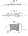
- Fig. 2 shows a preform 10 from which the label according to the invention can be formed by applying a leaflet.
- the preform 10 comprises a carrier web 11 provided with an upper side 12 with a silicone release layer.
- the carrier web 11 may also be formed from paper, in which case the upper side 12 is provided with clay or a layer of polypropylene applied by co-extrusion.
- the preform 10 comprises a release layer 13 and a cover layer 14.
- the release layer is provided with a first release layer side edge 42 and a second release layer side edge 43.
- the cover layer 14 is provided with a first and a second cover-layer side edge 15, 16.
- the cover layer 14 comprises a line of weakening 17 in the form of two parallel series of perforations 18, 19 which extend through the material of the cover layer 14.
- Side regions 20, 21 of the cover layer 14 are releasably joined to the carrier web 11 via an adhesive.
- a central region 22 of the cover layer 14 is joined, via its adhesive, to the release layer 13, which in turn lies, in a non-adhesive manner, on the carrier web 11.
- the release layer 13 comprises two series of perforations 23, 24 which extend beneath the series of perforations 18, 19 of the cover layer 14, so that a tear strip 39 is formed.
- a line of weakening 25 is provided in the release layer 13, in the vicinity of the edge of the central region 22 of the cover layer 14, so that a strip of release material 39' is formed which can be detached from the cover layer 14.
- the entire underside 46 of the cover layer is coated with an adhesive.
- Fig. 3 shows a plan view of the preform, clearly illustrating how a tear strip 26 is formed between the two parallel series of perforations 18, 19.
- the release layer 13 extends primarily beneath the central region 22 of the cover layer 14, as indicated by the shaded area. Furthermore, the central region 22 is provided with a cutout 27 and with a further line of weakening 28.
- a leaflet By detaching the side region 21 and folding open the cover layer 14 and release layer 13 as shown in Fig. 3 along the line of weakening 28, it is possible to slide a leaflet between the carrier web 11 and the release layer 13, as shown in Fig. 4.
- a first leaflet side edge 40 is located in the vicinity of the line of weakening 28, where it sticks to the cover layer 14.
- a second leaflet side edge 41 is located in the vicinity of the tear strip 26.
- the leaflet 30 is not provided with an adhesive and bears virtually freely against the release layer 13, and is securely but releasably joined to the adhesive of the cover layer 14 in the region of the line of weakening 28.
- the backing layer 31 of the leaflet 30 is not provided with an adhesive or at most is provided with a weakly adhering adhesive, so that this backing layer is joined in a non-adhesive or weakly adhesive manner to the carrier web 11.
- Fig. 5 shows a plan view of the assembled label 35 according to the invention, clearly illustrating that a machine-readable code 36, which has been applied to the leaflet, such as for example a bar code which corresponds to a machine-readable code 37 on the cover layer 14, is visible in the cutout 27.
- a machine-readable code 36 which has been applied to the leaflet, such as for example a bar code which corresponds to a machine-readable code 37 on the cover layer 14, is visible in the cutout 27.
- Fig. 6 shows the label according to the present invention which has been stuck to a base 38, after which the tear strips 26 and 39 have been detached and the leaflet beneath the cover layer 14 has been removed.
- the side region 21 has been completely detached from the central region 22.
- the central part 22 can be folded back away from the base 38 and the leaflet 30 can be removed.
- the strip 39' of the release layer 13 (cf. Fig. 4) can be removed from the cover layer 14 along the line of weakening 25, so that the adhesive of the cover layer 14 lying against it is exposed.
- That part of the cover part 14 which is located between the series of perforations 18 and the line of weakening 25 can be stuck back onto the base 38, so that the cover layer 14, after removal of the leaflet, can continue to fulfil its information function. If the cover layer 14 is to be repeatedly attached to and removed from a base, it is possible for a plurality of lines of weakening 25 to be arranged parallel to and at a distance from one another in the release layer 13.
Landscapes
- Physics & Mathematics (AREA)
- General Physics & Mathematics (AREA)
- Engineering & Computer Science (AREA)
- Theoretical Computer Science (AREA)
- Packages (AREA)
- Adhesive Tapes (AREA)
Abstract
Description
- The invention relates to a label provided with a carrier web, a cover layer, which is joined to the carrier web by means of adhesive, and a leaflet which lies between the cover layer and the carrier web and has a first leaflet side edge and a second leaflet side edge, the cover layer being provided with a first cover-layer side edge, a first side region, which lies between the first cover-layer side edge and the first leaflet side edge, and a second side region, which lies between the second leaflet side edge and the second cover-layer side edge, via which side regions the cover layer is releasably joined to the carrier web and, after it has been released, can be stuck to a base, the cover layer comprising a line of weakening, which lies in the second side region, to allow the cover layer to be torn through.
- A label with leaflet of this type is known from an American patent US 4,621,837.
- The known label has a leaflet which is folded in accordion form and is enclosed between a removable cover layer and a backing layer, which backing layer is, in used condition, adhesively bonded to a base over its entire surface, and which backing layer is, in ready for use condition, bonded to a releasable carrier web. After the cover layer has been removed on one side from the backing layer, it can be folded back and the leaflet can be unfolded and read. In this case, one side of the leaflet remains permanently joined to the cover layer. The cover layer and leaflet can be detached from the base along a second perforated line.
- The known label has the drawback that the continuous backing layer, after removal of the carrier web, is stuck adhesively to a base over its entire length. If this base is curved, such as for example a cylindrical container such as a medicine bottle, stresses are produced in the label. As a result, the perforations in the cover layer may undesirably break open and undesired deformation of the label may occur.
- It is an object of the present invention to provide a label with leaflet of the abovementioned type in which relatively little label material is used and in which no stresses are formed in the label when it is stuck to a cylindrical base.
- It is a further object of the invention to provide a label in which the leaflet can be removed entirely and in which the upper side of the leaflet is also provided with readable information.
- It is a further object of the invention to provide a label which, after removal of the line of weakening and reading of the leaflet, possibly after the label has been removed, can be stuck back onto the base.
- For this purpose, the label according to the invention is characterized in that the cover layer is joined with the side regions sticking directly to the carrier web, and the leaflet bearing directly, by means of a rear side, against the carrier web.
- The fact that the side regions of the cover layer, after the carrier web has been released, are arranged so as to stick directly onto the base while the leaflet rests at least virtually freely against this base, prevents undesirable stresses when the label is being stuck around the base. As a result, there is no unnecessary tension imposed on the lines of weakening and deformation of the label is prevented. Since the leaflet, if desired, has a low adhesive force or, preferably, is even not provided with an adhesive at all, this leaflet, when the label is being applied to a curved surface, can slide over it so that the stresses can be absorbed and the position of the label is determined solely by the position of the side regions of the cover layer.
- Preferably, a release layer is positioned between the side regions of the cover layer, beneath a central part thereof, against which release layer the leaflet is positioned, if appropriate releasably via an adhesive. The release layer prevents the cover layer from sticking to the carrier web before the leaflet is put in place under the cover layer and prevents adhesion of the leaflet to the central part of the cover layer. Cutting through the cover layer in order to form the lines of weakening is also made easier by the release layer.
- According to a preferred embodiment, the upper side of the leaflet bears freely against the release layer. This counteracts undesirable stresses when the label is being stuck around a curved base. Further this facilitates removal of the leaflet from the label.
- According to a further preferred embodiment, the leaflet is, in the region of the first leaflet side edge, releasably adhered to the cover layer. This facilitates opening the label as well as the leaflet without necessitating to remove the leaflet from the label to be able to read it.
- In order to improve the adhesion of the leaflet to the cover layer, whilst still being able to remove the leaflet from the cover layer or to read the leaflet while still being adhered to the cover layer, it is according to the invention advantageous when the release layer has a first release layer side edge at the side of the first leaflet side edge, and when the leaflet has a projecting region projection beyond the first release layer side edge and releasably adhering to the cover layer.
- In order to simplify production and to avoid applying adhesive to specific regions of the label, it is according to the invention advantageous when the cover layer is provided with an adhesive on its underside. This adhesive layer can be utilised for adhering the release layer, preferably releasable, to the cover layer, for adhering the leaflet releasable to the cover layer as well as for adhering the label to the carrier web or an object/base.
- After the label has been released from the carrier web, the side regions of the cover layer come off the carrier web, while the leaflet adheres releasably to the cover layer. Then, the side regions are applied to a base and the leaflet can be removed by detaching the line of weakening, folding open the cover layer and pulling the leaflet off the cover layer. In the process, the top side, the rear side and the inside of the leaflet can be provided with relevant information. The leaflet may, for example, be in the form of a booklet, the pages of which are joined to one another on one side, or may be folded in accordion form. As the release layer is not removed, information provided on it, will still be present after removal of the leaflet.
- The release layer may comprise a second line of weakening which, in the direction of the first leaflet side edge, lies at a distance from the first line of weakening in the release layer, the release layer being releasable between the two side edge regions of the cover layer. After the line of weakening of the cover layer and of the release layer has been broken, the label can be folded back. Then, the section of the release layer which lies along the free edge of the folded-open cover layer can be removed and the narrow cover-layer strip which has been exposed and is also provided with adhesive can be stuck back onto the base.
- In a preferred embodiment of a label according to the invention, a machine-readable code is applied to the cover layer and to the leaflet, the cover-layer material having been removed or being transparent at the location of the code. In this way, it is possible to verify that both the leaflet and the cover layer are provided with corresponding, for example identical, information, so that even after removal of the leaflet it can be related to the cover layer. This is desirable, for example, if the label is stuck to a medicine bottle, the leaflet is removed and is subsequently stuck onto a patient's records card or into a record book.
- The invention further relates to an assembly of a base and label according to the invention without carrier web, the label without carrier web being stuck on the base via the first and second side region.
- An embodiment of a label according to the present invention will be explained in more detail with reference to the appended drawing, in which:
- Fig. 1 shows a label with leaflet according to the prior art;
- Fig. 2 shows a preform of the label according to the invention, without the leaflet;
- Fig. 3 shows a label with leaflet formed from the preform as shown in Fig. 2;
- Fig. 4 shows a side view of the cover layer according to the invention;
- Fig. 5 shows the cover layer according to the invention, positioned above a leaflet provided with a machine-readable code; and
- Fig. 6 shows the label which has been applied to a base after removal of the leaflet.
-
- Fig. 1 shows a known
label 1, comprising acontinuous carrier web 2 which is wound, for example, onto a reel. Thecarrier web 2 is provided on anupper side 3 with a release layer, such as for example a layer of silicones, to which a backing layer 4 is releasably joined, for example by means of a pressure-sensitive adhesive. Acover layer 5 is fixedly joined to the backing layer 4 and aleaflet 6 is accommodated between thecover layer 5 and the backing layer 4. The backing layer 4,cover layer 5 andleaflet 6 can be removed from thecarrier web 3 as a single unit and stuck to a base. Thecover layer 5 can then be detached along a line of weakening 7, which may, for example, comprise two parallel series of perforations, so that thecentral part 8 of thecover layer 5 can be folded back and theleaflet 6 comes away from the backing layer 4. Theleaflet 6 can then be pulled out in the manner of an accordion and the information on the leaflet can be read. - Fig. 2 shows a
preform 10 from which the label according to the invention can be formed by applying a leaflet. Thepreform 10 comprises acarrier web 11 provided with anupper side 12 with a silicone release layer. However, thecarrier web 11 may also be formed from paper, in which case theupper side 12 is provided with clay or a layer of polypropylene applied by co-extrusion. Thepreform 10 comprises arelease layer 13 and acover layer 14. The release layer is provided with a first releaselayer side edge 42 and a second releaselayer side edge 43. Thecover layer 14 is provided with a first and a second cover-layer side edge cover layer 14 comprises a line of weakening 17 in the form of two parallel series ofperforations cover layer 14.Side regions cover layer 14 are releasably joined to thecarrier web 11 via an adhesive. Acentral region 22 of thecover layer 14 is joined, via its adhesive, to therelease layer 13, which in turn lies, in a non-adhesive manner, on thecarrier web 11. Therelease layer 13 comprises two series ofperforations perforations cover layer 14, so that atear strip 39 is formed. Furthermore, a line of weakening 25 is provided in therelease layer 13, in the vicinity of the edge of thecentral region 22 of thecover layer 14, so that a strip of release material 39' is formed which can be detached from thecover layer 14. Preferably theentire underside 46 of the cover layer is coated with an adhesive. - Fig. 3 shows a plan view of the preform, clearly illustrating how a
tear strip 26 is formed between the two parallel series ofperforations release layer 13 extends primarily beneath thecentral region 22 of thecover layer 14, as indicated by the shaded area. Furthermore, thecentral region 22 is provided with acutout 27 and with a further line ofweakening 28. By detaching theside region 21 and folding open thecover layer 14 andrelease layer 13 as shown in Fig. 3 along the line of weakening 28, it is possible to slide a leaflet between thecarrier web 11 and therelease layer 13, as shown in Fig. 4. In this case, a firstleaflet side edge 40 is located in the vicinity of the line of weakening 28, where it sticks to thecover layer 14. A secondleaflet side edge 41 is located in the vicinity of thetear strip 26. On anupper side 32, theleaflet 30 is not provided with an adhesive and bears virtually freely against therelease layer 13, and is securely but releasably joined to the adhesive of thecover layer 14 in the region of the line ofweakening 28. Thebacking layer 31 of theleaflet 30 is not provided with an adhesive or at most is provided with a weakly adhering adhesive, so that this backing layer is joined in a non-adhesive or weakly adhesive manner to thecarrier web 11. - Fig. 5 shows a plan view of the assembled
label 35 according to the invention, clearly illustrating that a machine-readable code 36, which has been applied to the leaflet, such as for example a bar code which corresponds to a machine-readable code 37 on thecover layer 14, is visible in thecutout 27. - Fig. 6 shows the label according to the present invention which has been stuck to a
base 38, after which the tear strips 26 and 39 have been detached and the leaflet beneath thecover layer 14 has been removed. As a result, theside region 21 has been completely detached from thecentral region 22. After removal of thetear strip 26 and the strip ofrelease material 39 located beneath it, thecentral part 22 can be folded back away from thebase 38 and theleaflet 30 can be removed. Then, the strip 39' of the release layer 13 (cf. Fig. 4) can be removed from thecover layer 14 along the line of weakening 25, so that the adhesive of thecover layer 14 lying against it is exposed. That part of thecover part 14 which is located between the series ofperforations 18 and the line of weakening 25 can be stuck back onto thebase 38, so that thecover layer 14, after removal of the leaflet, can continue to fulfil its information function. If thecover layer 14 is to be repeatedly attached to and removed from a base, it is possible for a plurality of lines of weakening 25 to be arranged parallel to and at a distance from one another in therelease layer 13.
Claims (13)
- Label (35) provided with a carrier web (11), a cover layer (14), which is joined to the carrier web (11) by means of adhesive, and a leaflet (30) which lies between the cover layer (14) and the carrier web (11) and has a first leaflet side edge (40) and a second leaflet side edge (41), the cover layer (14) being provided with a first cover-layer side edge (15), a first side region (20), which lies between the first cover-layer side edge (15) and the first leaflet side edge (40), and a second side region (21), which lies between the second leaflet side edge (41) and the second cover-layer side edge (16), via which side regions the cover layer is releasably joined to the carrier web and, after it has been released, can be stuck to a base, the cover layer (14) comprising a line of weakening (18, 19), which lies in the second side region (21), to allow the cover layer to be torn through, characterized in that the cover layer (14) is joined with the side regions (20, 21) sticking directly to the carrier web (11), and the leaflet (30) bearing directly, by means of a rear side (31), against the carrier web (11).
- Label (35) according to claim 1, in which the rear side (31) of the leaflet is not provided with an adhesive.
- Label (35) according to claim 1 or 2, characterized in that a release layer (13) is positioned beneath the cover layer (14), between the side regions (20, 21) of the cover layer (14), against which release layer the leaflet (30) is releasably positioned.
- Label (35) according to claim 3, characterized in that the upper side (32) of the leaflet (30) bears freely against the release layer.
- Label (35) according to claim 4, characterized in that the leaflet (3) is, in the region of the first leaflet side edge (40), releasably adhered to the cover layer.
- Label (35) according to one of the claims 3-5, characterized in that the release layer has a first release layer side edge (42) at the side of the first leaflet side edge (40), and in that the leaflet (30) has a projecting region (44) projection beyond the first release layer side edge (42) and releasably adhering to the cover layer (14).
- Label (35) according to one of the claims 3-6, characterized in that the cover layer (14) is provided with an adhesive on its underside (46).
- Label (35) according to one of the claims 3-7, in which a line of weakening (23, 24) is arranged in the release layer (13) below the line of weakening (18, 19) in the cover layer (14).
- Label (35) according to one of the preceding claims, in which the line of weakening (18, 19, 23, 24) in the cover layer (14) and/or in the release layer (13) comprises two series of perforations which are parallel to and at a distance from one another.
- Label (35) according to one of the preceding claims, characterized in that the release layer (13) comprises a second line of weakening (25) which lies at a distance, in the direction of the second leaflet side edge (41), from the first line of weakening (23, 24) in the release layer (13), the release layer being releasable from the cover layer (14) between the two lines of weakening (23, 24).
- Label (35) according to one of the preceding claims, characterized in that a machine-readable code (36, 37) is applied to the leaflet (30) and to the cover layer (14), the cover-layer material (14) having been removed or being transparent at the location of the code (36).
- Label according to one of the preceding claims, characterized in that the cover layer (14) comprises a line of weakening (28) in the first side region (20), said line of weakening (28) preferably lying adjacent the first leaflet side edge (40).
- Assembly of a base (38) and label (35) according to one of the preceding claims without carrier web (11), the label (35) without carrier web (11) being stuck on the base (38) via the first (20) and second (21) side region.
Priority Applications (1)
| Application Number | Priority Date | Filing Date | Title |
|---|---|---|---|
| EP02075816A EP1237137A3 (en) | 2001-03-01 | 2002-03-01 | Adhesive label with leaflet assembly |
Applications Claiming Priority (3)
| Application Number | Priority Date | Filing Date | Title |
|---|---|---|---|
| EP01200772 | 2001-03-01 | ||
| EP01200772 | 2001-03-01 | ||
| EP02075816A EP1237137A3 (en) | 2001-03-01 | 2002-03-01 | Adhesive label with leaflet assembly |
Publications (2)
| Publication Number | Publication Date |
|---|---|
| EP1237137A2 true EP1237137A2 (en) | 2002-09-04 |
| EP1237137A3 EP1237137A3 (en) | 2004-12-15 |
Family
ID=26076845
Family Applications (1)
| Application Number | Title | Priority Date | Filing Date |
|---|---|---|---|
| EP02075816A Withdrawn EP1237137A3 (en) | 2001-03-01 | 2002-03-01 | Adhesive label with leaflet assembly |
Country Status (1)
| Country | Link |
|---|---|
| EP (1) | EP1237137A3 (en) |
Cited By (2)
| Publication number | Priority date | Publication date | Assignee | Title |
|---|---|---|---|---|
| WO2007054713A1 (en) * | 2005-11-11 | 2007-05-18 | Beverley Ward | Information carrier |
| US11247807B2 (en) | 2016-02-11 | 2022-02-15 | Glaxosmithkline Intellectual Property Management Limited | Healthcare product package |
Citations (6)
| Publication number | Priority date | Publication date | Assignee | Title |
|---|---|---|---|---|
| US4991878A (en) * | 1990-05-10 | 1991-02-12 | Ccl Product Identification, Inc. | Label assembly with removable booklet |
| US5207458A (en) * | 1991-06-29 | 1993-05-04 | Bayer Aktiengesellschaft | Multi-layered label |
| US5290616A (en) * | 1992-11-27 | 1994-03-01 | Ccl Label, Inc. | Resealable overlaminated leaflet label |
| EP0743627A1 (en) * | 1995-05-16 | 1996-11-20 | Denny Bros. Printing Limited | Adhesive label/leaflet assemblies |
| US5766716A (en) * | 1996-08-08 | 1998-06-16 | Inprint Systems, Inc. | Self-adhesive labels |
| CA2195135A1 (en) * | 1997-01-15 | 1998-07-15 | Christian J. Schostek | Adhesive label system |
-
2002
- 2002-03-01 EP EP02075816A patent/EP1237137A3/en not_active Withdrawn
Patent Citations (6)
| Publication number | Priority date | Publication date | Assignee | Title |
|---|---|---|---|---|
| US4991878A (en) * | 1990-05-10 | 1991-02-12 | Ccl Product Identification, Inc. | Label assembly with removable booklet |
| US5207458A (en) * | 1991-06-29 | 1993-05-04 | Bayer Aktiengesellschaft | Multi-layered label |
| US5290616A (en) * | 1992-11-27 | 1994-03-01 | Ccl Label, Inc. | Resealable overlaminated leaflet label |
| EP0743627A1 (en) * | 1995-05-16 | 1996-11-20 | Denny Bros. Printing Limited | Adhesive label/leaflet assemblies |
| US5766716A (en) * | 1996-08-08 | 1998-06-16 | Inprint Systems, Inc. | Self-adhesive labels |
| CA2195135A1 (en) * | 1997-01-15 | 1998-07-15 | Christian J. Schostek | Adhesive label system |
Cited By (2)
| Publication number | Priority date | Publication date | Assignee | Title |
|---|---|---|---|---|
| WO2007054713A1 (en) * | 2005-11-11 | 2007-05-18 | Beverley Ward | Information carrier |
| US11247807B2 (en) | 2016-02-11 | 2022-02-15 | Glaxosmithkline Intellectual Property Management Limited | Healthcare product package |
Also Published As
| Publication number | Publication date |
|---|---|
| EP1237137A3 (en) | 2004-12-15 |
Similar Documents
| Publication | Publication Date | Title |
|---|---|---|
| US6682798B1 (en) | Expanded content device pouch | |
| US5804271A (en) | Self-adhesive labels | |
| US4529229A (en) | Labels | |
| JP4156875B2 (en) | Label for sticking to the container | |
| EP0612426B1 (en) | Labels and manufacture thereof | |
| US6432500B1 (en) | Label with booklet | |
| WO1999067767A1 (en) | Labels | |
| JP2001506380A (en) | Labels to be applied especially to cylindrical containers and containers provided with such labels | |
| EP1098766B1 (en) | Label with applied handle | |
| US5660896A (en) | Identification card and carrier | |
| AU715607B2 (en) | Adhesive label/leaflet assemblies | |
| JPH01502416A (en) | self loading binder | |
| EP0256672B1 (en) | Labels and manufacture thereof | |
| JP4436636B2 (en) | Multilayer label, receptacle provided with multilayer label, and method of manufacturing multilayer label | |
| EP0090882B1 (en) | Improvements in or relating to labels | |
| EP1237137A2 (en) | Adhesive label with leaflet assembly | |
| JP2002524301A (en) | Adhesive label and method for producing the same | |
| US6129387A (en) | Pressure sensitive library card holder | |
| US20030133743A1 (en) | Overlay binder including perforated easy-release label leader | |
| US20050230964A1 (en) | Label | |
| CA1274980A (en) | Labels | |
| GB2213428A (en) | Leaflets | |
| MXPA99001318A (en) | Self-adhesive labels |
Legal Events
| Date | Code | Title | Description |
|---|---|---|---|
| PUAI | Public reference made under article 153(3) epc to a published international application that has entered the european phase |
Free format text: ORIGINAL CODE: 0009012 |
|
| AK | Designated contracting states |
Kind code of ref document: A2 Designated state(s): AT BE CH CY DE DK ES FI FR GB GR IE IT LI LU MC NL PT SE TR |
|
| AX | Request for extension of the european patent |
Free format text: AL;LT;LV;MK;RO;SI |
|
| PUAL | Search report despatched |
Free format text: ORIGINAL CODE: 0009013 |
|
| AK | Designated contracting states |
Kind code of ref document: A3 Designated state(s): AT BE CH CY DE DK ES FI FR GB GR IE IT LI LU MC NL PT SE TR |
|
| AX | Request for extension of the european patent |
Extension state: AL LT LV MK RO SI |
|
| STAA | Information on the status of an ep patent application or granted ep patent |
Free format text: STATUS: THE APPLICATION IS DEEMED TO BE WITHDRAWN |
|
| 18D | Application deemed to be withdrawn |
Effective date: 20041001 |