BACKGROUND OF THE INVENTION
1. Field of the Invention
The present invention relates to a back light unit for
liquid crystal display device, more particularly to a back light
unit for portable terminal equipment.
2. Discussion of the Related Art
A liquid crystal display (LCD) device is widely used for
a display device for information equipment such as a mobile
telephone, personal digital assistants (PDA) and a computer etc.
LCD requires a light source because it is a non-emissive
device. LCD can be classified into a reflection type LCD and
a transmission type LCD depending upon a lighting method. In
the reflection type LCD, incident light from the front side (the
side facing to an observer) of a liquid crystal panel is reflected
on the liquid crystal panel and the reflected light is visible.
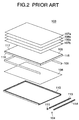
As shown in FIG. 1, the transmission type LCD 101 is provided
with a liquid crystal panel 102 and a backlight unit 103 arranged
on the rear side of the liquid crystal panel 102.
The backlight unit 103 emits light to the liquid crystal
panel 102 from the rear side and the light passing through the
liquid crystal panel 102 is visible to the observer on the front
side.
The backlight unit 103 is provided with a light source
unit 104, a light guide plate 105, a first lens film 106a, a
second lens film 106b, a first diffuser 107a, a second diffuser
107b, a reflector 108, a strip reflector 109 and a holding frame
110 as shown in FIGs. 1 and 2.
The light source unit 104 is provided with a spotlight
111 formed by a white light emitting diode (LED) and others,
a light guide 113 made of transmissible material for leading
light emitted from the spotlight 111 in a elongated direction
and emitting as band light from a light outgoing face 112 (see
FIG. 1) which is one side and a reflector part 114 which covers
the three sides except the light outgoing face 112 of the light
guide 113 and the section of which is substantially U-shaped
as shown in FIG. 2.
The light guide plate 105 is formed by a flat part made
of transmissible material and is arranged so that a side 115
of the light guide plate 105which is an end face on one side
is opposite to the light outgoing face 112 of the light source
unit 104. In the light guide plate 105, the end face of incident
light side 115 receives band light outgoing from the light source
unit 104, the light is reflected on a light reflecting surface
116 substantially perpendicular to the end face of incident light
side 115 and area light is radiated from a light radiation surface
117 opposite to the light reflecting surface 116 toward the liquid
crystal panel 102 arranged on the front side of the backlight
unit 103.
The first lens film 106a and the second lens film 106b
converge light outgoing from the light radiation surface 117
arranged on the front side of the light guide plate 105 and secure
predetermined luminance.
The first diffuser 107a and the second diffuser 107b are
respectively arranged between the first lens film 106a and the
liquid crystal panel 102 and between the second lens film 106b
and the light guide plate 105, correct the dispersion of luminance
and enhance the uniformity of luminance.
The reflector 108 is arranged on the rear side of the light
guide plate 105, receives light outgoing from the light guide
plate 105 and reflects it toward the light guide plate 105.
The strip reflector 109 is arranged so that it is opposite
to the three side end faces of the light guide plate 105 except
the end face of incident light side 115 opposite to the light
source unit 104.
The holding frame 110 is a part like a tray, the reflector
108 is laid at the bottom, the strip reflector 109 is bonded
to the inner wall, and the light source unit 104 and the light
guide plate 105, first lens film 106a, second lens film 106b,
first diffuser 107a and second diffuser 107b which are laminated
are laid and held on the reflector 108.
The light reflecting surface 116 of the light guide plate
105 may have the irregular surface such as emboss or a frosting
face or for example, circular dot-shaped material having high
reflectivity is printed via a screen.
Technique for reflecting and diffusing incident light from
the light source unit 104 with the rear surface of the light
guide plate 105 having rough surface as described above is
disclosed in Japanese Patent Laid-open No. 2000-155309.
However, as incident light on the light reflecting surface
116 of the light guide plate 105 from the light source unit 104
is irregularly reflected on the surface, it does not have large
directivity. Therefore, as described above, unless using the
first lens film 106a and the second lens film 106b, predetermined
luminance cannot be secured.
In the case that there is sufficient ambient light when
a LCD is used outdoors, it may be desired that the spotlight
111 is unlit from the viewpoint of saving power and only a power
unit in the body of electronic equipment such as a mobile telephone
having backlight unit 103 is mounted is turned on. The spotlight
111 may be unlit because of failure.
As described above, in case display only by ambient light
is desired, there is a problem that ambient light from the side
of the liquid crystal panel 102 attenuates passing plural lens
films and even if the ambient light is efficiently reflected
at the light reflecting surface 116, the intensity is too weak
to light the liquid crystal panel 102.
To solve this problem, Japanese Patent Laid-open No. Hei
11-295714 shows a technique for enhancing the directivity of
reflected light by turning the rear surface of a light guide
plate into a prismatic surface.
However, this prismatic surface provided to the rear
surface of the light guide plate 105 is provided only to enhance
the directivity of illuminating light in a predetermined
direction when incident light from a band light source is
reflected forward (on the side of the liquid crystal panel).
That is, this prismatic surface is provided to converge
light diffusing in the elongated direction of the band light
source. Therefore, protrusions formed by a pair of slant faces
are repeatedly formed on the prismatic surface in the elongated
direction of the band light source. In other words, this
prismatic surface is formed so that a direction of the ridge
line is perpendicular to the elongated direction of the band
light source.
Therefore, the direction of the highest luminance of light
from the light guide plate remains inclined by a predetermined
angle in an orientation apart from the band light source.
Therefore, to converge this illuminating light and make
the direction in which the illuminating light has the highest
luminance approach a direction perpendicular to the outgoing
face, the lens films are required between the light guide plate
and the liquid crystal panel. The prismatic surface of the lens
film is formed so that a direction of the ridge line is parallel
to the elongated direction of the band light source.
However, the ambient light attenuates in the lens film
as described above.
In the technique disclosed in this patent application,
there is no idea to'utilize ambient light and the prismatic surface
provided to the rear surface of the light guide plate is not
designed to utilize ambient light.
Therefore, even if ambient light reaches the prismatic
surface of the light guide plate without attenuating so much,
it is not efficiently reflected forward and it is difficult to
utilize the ambient light as illuminating light.
Heretofore, a light guide plate that radiates light emitted
from a light source forward and simultaneously, can efficiently
reflect ambient incident light from the front side forward has
not been proposed and the idea itself has not been existed. It
was difficult to utilize both emitted light from a light source
and ambient light as illuminating light.
Therefore, there is a problem that the display cannot be
used when the spotlight 111 is unlit and it is difficult to achieve
high luminance.
As described above, as the plural lens films are required
to be necessarily arranged between the light guide plate and
the liquid crystal panel, there is a problem that the number
of parts is increased and thinning, miniaturization and the
reduction of the cost are obstructed.
The invention is made in view of the above-mentioned
situations and the object is to provide a backlight in which
display on a liquid crystal panel is enabled utilizing ambient
light even if the spotlight 111 is unlit and high luminance can
be achieved, and to provide LCD with the backlight and portable
terminal equipment with the LCD.
Also, another object is to provide a backlight the number
of parts of which is reduced, keeping high luminance to thin
and miniaturize the backlight and the cost of which can be reduced,
and to provide LCD with the backlight and portable terminal
equipment with the LCD.
SUMMARY OF THE INVENTION
A backlight unit for a LCD device according to the invention
is provided with a light guide plate, at least one light source
unit provided to at least one side of the light guide plate,
a reflector provided so that it is opposite to the rear surface
of the light guide plate, plural reflection regions and plural
transmission regions provided to the rear surface of the light
guide plate and is characterized in that an angle between the
surface opposite to the rear surface of the light guide plate
and at least one of the reflection regions is larger than an
angle between the surface and at least one of the transmission
regions. The backlight unit for the LCD device according to
the invention is also characterized in that portable terminal
equipment is provided with the backlight unit for the LCD device.
BRIEF DESCRIPTION OF THE DRAWINGS
FIG. 1 is a schematic block diagram showing a conventional
type transmission type LCD device;
FIG. 2 is an exploded perspective view showing a
conventional type backlight;
FIG. 3 is an exploded perspective view showing the
configuration of a backlight equivalent to one embodiment of
the invention;
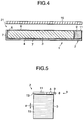
FIG. 4 is a sectional view showing the configuration of
a LCD device using a backlight according to the invention;
FIG. 5 is a plan showing a light source unit and a light
guide plate forming the backlight according to the invention
in a state in which a part is broken;
FIG. 6 is a plan showing a part A in FIG. 5 in an enlarged
state;
FIG. 7 is a sectional view viewed along a line B-B in FIG.
6;
FIG. 8 is a sectional view showing the configuration of
the light source unit and the light guide plate;
FIG. 9 is an explanatory drawing for explaining the
operation of the backlight according to the invention;
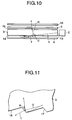
FIG. 10 is an explanatory drawing for explaining the
operation of the backlight according to the invention;
FIG. 11 an explanatory drawing for explaining the operation
of the backlight according to the invention;
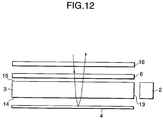
FIG. 12 is an explanatory drawing for explaining the
operation of the backlight according to the invention;
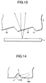
FIG. 13 is an explanatory drawing for explaining the
operation of the backlight according to the invention;
FIG. 14 is a sectional view showing the configuration of
a light guide plate of a backlight equivalent to another
embodiment of the invention;
FIG. 15 is a perspective view showing the configuration
of a portable information terminal as electronic equipment using
the backlight according to the invention; and
FIG. 16 is a perspective view showing the configuration
of a mobile telephone as electronic equipment using the backlight
according to the invention.
DETAILED DESCRIPTION OF THE PREFERRED EMBODIMENTS
The invention will be now described herein with reference
to illustrate embodiments. Those skilled in the art will
recognize that many alternative embodiments can be accomplished
using the teachings of the present invention and that the
invention is not limited to the embodiments illustrated for
explanatory purposes.
Preferred embodiments of the invention will be described
below.
First, a backlight equivalent to one embodiment of the
invention will be described.
The backlight equivalent to this embodiment is provided
with a light source unit, a light guide plate and a reflector.
The light source unit emits substantially band-shaped light from
the side. The light guide plate receives the light emitted from
the light source unit and reflects it to the front surface at
the prismatic surface provided at the back surface. The
reflector is arranged opposing to the prismatic surface of the
light guide plate for reflecting light from the prismatic surface
toward the front surface. The prismatic surface has plural
reflection regions and plural transmission regions. The
reflection regions reflect incident light toward front surface.
The transmission regions transmit ambient light and the ambient
light reflects at the reflector and passes through the
transmission part to the front surface.
An angle between the surface of the light guide plate
opposite to the rear surface and at least one of the reflection
regions is larger than an angle between the surface and at least
one of the transmission regions. Hereby, ambient light reaches
mainly the transmission regions of the prismatic surface and
is utilized as illuminating light.
Therefore, ambient light from the liquid crystal panel
can be also made the best use of to illuminate the liquid crystal
panel and the luminance can be enhanced.
As the lens films provided on the front side of the light
guide plate of the conventional type backlight are removed,
ambient light from the liquid crystal panel reaches the light
guide plate without attenuating so much even if the ambient light
is relatively weak. Therefore, the ambient light can be securely
utilized as illuminating light.
In case that intense of ambient light is enough, an observer
can view display of the liquid crystal panel even if the light
source unit is turned off. Therefore, the backlight equivalent
to this embodiment can contribute to power saving. Even if the
light source unit is turned off because of failure, an observer
can view display of the liquid crystal panel.
As lens films for convergence are not required to be
arranged between the light guide plate and the liquid crystal
panel, the number of the parts can be reduced and the cost of
the backlight can be reduced.
Next, referring to the drawings, the backlight equivalent
to one embodiment of the invention will be described.
The backlight 1 equivalent to this embodiment is provided
with a light source unit 2, a light guide plate 3, a reflector
4, a strip reflector 5, a diffuser 6 and a holding frame 7 as
shown in FIGs. 3 and 4.
The light source unit 2 is provided with a spotlight 8
made of white LED, a rod light guide 9 that radiates light emitted
from the spotlight 8 from the light outgoing face 9a a rod light
guide 9 toward the light guide plate 3 and a U-shaped reflecting
part 11 as shown in FIGs. 3 and 7.
The rod light guide 9 is made of transmissible material
such as acrylic resin and a wedge type concave portion 9c is
regularly formed on the side of the opposite surface 9b opposite
to the light guide plate 3 as shown in FIGs. 6 and 7.
The reflecting part 11 is made of metal such as aluminum
and resin to which a white film is applied on the surface for
reflecting light and is bonded to the rod light guide 9 so that
the reflecting part covers three sides of the rod light guide
9 except the light outgoing face 9a.
In a joint in which the concave portion 9c is formed out
of the joints of the light guide 9 and the reflecting part 11,
a substantially prismatic space 12 including air is formed.
The light guide plate 3 is formed by a flat plate which.
is made of acrylic resin for example. As shown in FIG. 8, the
light guide plate 3 is arranged so that the side 13 is opposite
to the light outgoing face 9a of the rod light guide 9 of the
light source unit 2. The light guide plate 3 receives light
from the side 13 and reflects the light at the.rear surface 14
to the front surface.
An angle between a front surface 15 of the light guide
plate 3 opposite to the rear surface 14 and the reflection regions
17 is larger than an angle between the front surface and the
transmission regions 18.
As shown in FIG. 11, the reflection region 17 reflects
incident light "S" from the side 13 so that light "R" is utilized
to illuminate the liquid crystal panel 16, and is inclined at
an angle of approximately 40 to 50□ with the front surface 15
for example.
As shown in FIG. 13, the transmission region 18 transmits
most of the ambient light from the front surface 15 and passes
some of the ambient light. The light is reflected at the
reflector 4 toward the front surface 15 so that the light is
utilized as illuminations for the liquid crystal panel 16. The
transmission region 18 is inclined at an angle of a few degrees
with the front surface 15 for example.
The reflection region 17 and the transmission region 18
are periodically formed at predetermined pitch p (for example,
p = 100 µm) as shown in FIG. 5. The rear surface 14 is formed
so that a direction of a ridge line is parallel to an elongated
direction x of the rod light guide 9 as shown in FIG. 5.
Light without being reflected on the reflection region
17 is also reflected at the reflector 4 and passes through the
transmission region 18 toward the front surface 15.
The reflector 4 is arranged opposing to the rear surface
of the light guide plate 3 and reflects light from the light
guide plate 3 toward the front surface 15.
The strip reflector 5 is arranged to surround three sides
of the light guide plate 3 except the side 13 opposite to the
light source unit 2 and reflects light that leaks from the three
sides of the light guide plate 3.
The diffuser 6 is arranged between the light guide plate
3 and the liquid crystal panel 16, corrects the dispersion of
luminance and enhances the uniformity of luminance.
The reflector 4 is laid at the bottom of the holding frame
7, the strip reflector 5 is bonded to the inner wall, the light
source unit 2 and the laminated light guide plate 3 and diffuser
6 are laid and held on the reflector 4.
The backlight 1 equivalent to this embodiment forms LCD
21 by being arranged on the rear side of the transmission type
liquid crystal panel 16. The backlight 1 radiates illuminating
light toward the liquid crystal panel 16, also reflects ambient
light from the front surface of the liquid crystal panel 16 toward
the liquid crystal panel 16 and makes an observer visible. Even
if the spotlight 8 is unlit, ambient light transmitted through
the liquid crystal panel 16 is reflected and used for illuminating
the liquid crystal panel 16.
The liquid crystal panel 16 is provided with a substrate
where multiple transparent pixel electrodes are formed, an
opposite substrate which is fixed opposite to the substrate via
the clearance of a few µm and where a colored layer (a color
filter) is formed, a liquid crystal layer filled in the clearance
and a pair of deflecting plates arranged outside the substrate
and outside the opposite substrate.
Next, the operation of the backlight 1 equivalent to this
embodiment will be described.
As shown in FIGs. 3 and 9, light emitted from the spotlight
8 is propagated inside the rod light guide 9 and reaches a boundary
portion 210 between the rod light guide 9 and the reflecting
part 11. A part of the light is reflected at a boundary surface
22 between the rod light guide 9 and the reflecting part 11 and
a part of the light is reflected at a boundary surface 23 between
the rod light guide 9 and the space 12 and a part of the light
is deflected at the boundary surface 23 and the light totally
outgoes from the light outgoing face 9a, advancing in a elongated
direction "x" and is incident on the side 13 as substantially
even band light.
As shown in FIGs. 10 and 11, the light "S" from the side
13 of the light guide plate 3 reaches reflection region 17 and
most of the light is reflected at the reflection region 17 to
the front surface 15 in a direction shown as "R" in FIG. 11.
A slight part of light that reaches the reflection region
17 is transmitted through the reflection region 17 as leaked
light "T". However, the light that is reflected at the reflector
4 to the front surface 15 and is utilized as illumination.
The above-mentioned direction of the light "R" reflected
to the front surface 15 is substantially even and has the highest
luminance at a direction substantially coincident with a normal
direction of the front surface 15.
The light "R" is transmitted in the diffuser 6 to correct
dispersion of luminance and utilized as illumination of the
liquid crystal panel 16. When the light passes the diffuser
6, Moire fringes which are interference fringes produced between
the ridge line of the rear surface 14 and the array of picture
elements of the liquid crystal panel 16 substantially disappear
in case they are viewed from the side of an observer.
Next, a case when the spotlight 8 is unlit will be described.
As shown in FIGs. 12 and 13, when ambient light reaches
the backlight from the side of the liquid crystal panel 16, it
is first transmitted in the diffuser 6. At this time, the
quantity of attenuation after transmission of the intensity of
the ambient light is slight. This transmitted light is incident
on the light guide plate 3 from the front surface 15 and further,
reaches mainly the transmission region 18 of the rear surface
14.
Most of the incident light is deflected at the transmission
region 18 and is reflected at the reflector 4 to the front surface
15. The light is utilized as illumination of the liquid crystal
panel 16. The transmittance of the light guide plate 3 is
relatively high and the attenuation of the ambient light is
relatively small.
It is also performed when the spotlight 8 is lit that ambient
light is reflected and irradiates the liquid crystal panel 16.
Therefore, ambient light from the side of the liquid
crystal panel 16 can be also made the best use of to illuminate
the liquid crystal panel 16. Therefore, the luminance can be
enhanced.
As the lens films provided on the front side of the light
guide plate of the conventional type backlight are removed,
ambient light which from the side of the liquid crystal panel
16 reaches the light guide plate 3 without being attenuated so
much even if the ambient light is relatively weak. Therefore,
the ambient light can be securely utilized as illuminating light.
In case ambient light has enough intensity, an observer
can view display on the liquid crystal panel 16 even if the
spotlight 8 is unlit. Therefore, this invention can contribute
to power saving. Even if the spotlight 8 is unlit because of
failure, an observer can view display on the liquid crystal panel
16.
In addition, because the prismatic surface of the light
guide plate 3 is optimally designed to use for a front light
type, it can be used as it is without being changed so as to
reflect ambient light at the rear surface 14.
As described above, as the plural lens films for
convergence are not required to be arranged between the light
guide plate 3 and the liquid crystal panel 16, the number of
parts can be reduced and the cost of the backlight can be reduced.
As white LED of the spotlight is used for a light source,
an inverter required in case a fluorescent lamp is used is not
required, and the backlight 1 and LCD 21 provided with the
backlight 1 can be miniaturized and lightened.
Referring to the drawings, the embodiment of the invention
has been described in detail, however, the concrete configuration
is not limited to this embodiment and even if the change of design
in a range which does not deviate from the object of the invention
is made, it is included in this invention.
For example, in the above-mentioned embodiment, the case
that for the prismatic surface, the abruptly inclined reflection
region 17 and the gently inclined transmission region 18 are
repeated is described, however, the uniformity of the luminance
of area illuminating light radiated from a light radiation
surface can be enhanced by forming a symmetrical wedge type groove
17A as a reflecting part and a flat part 18A as a transmission
part as shown in FIG. 14 and particularly applying the invention
to a case that a light guide and a spotlight are arranged on
the sides of opposite two side end faces of a light guide plate.
As shown in FIG. 15, a portable information terminal 31
such as PDA as electronic equipment can be acquired using LCD
21 provided with the backlight 1 described in the embodiment,
in the portable information terminal 31, the luminance is
enhanced, compared with that in the conventional type and even
if the backlight is unlit, the portable information terminal
can be used.
LCD 21 provided with the backlight according to this
invention may be also applied to a portable personal computer
and a notebook-sized personal computer except the portable
information terminal.
As shown in FIG. 16, a mobile telephone 41 can be acquired
using LCD 21 provided with the backlight according to this
invention, in the mobile telephone 41, the luminance is enhanced,
compared with that in the conventional type and even if the
backlight is unlit, the mobile telephone can be used.
The case that white LED is used for the spotlight 8 in
the light source unit 2 is described above, however, the spotlight
is not limited to white LED, LED that emits light of another
color (for example, red) may be also used and an incandescent
lamp may be also used in place of LED. The case that light emitted
from the spotlight 8 is converted to band light for radiation
is described above, however, a linear light source such as a
fluorescent lamp may be also used.
In the above-mentioned embodiments, the case that the rear
surface 14 is formed so that the direction of the ridge line
of the rear surface 14 is parallel to the elongated direction
"x" of the rod light guide 9 is described above, however, the
rear surface 14 may be also formed so that a direction of the
ridge line of the rear surface 14 becomes a direction turned
by a predetermined inclination counterclockwise (that is,
rising right) from the elongated direction "x" of the rod light
guide 9. In this case, the inclination is set to 23□ for example.
Hereby, Moire fringes produced between the ridge line of the
rear surface 14 and the array of picture elements of the liquid
crystal panel 16 can be more securely reduced.
In case the rear surface 14 is formed so that the direction
of the ridge line becomes the direction turned by the
predetermined inclination counterclockwise from the elongated
direction "x" of the rod light guide 9 as described above, the
diffuser 6 can be also omitted. Hereby, ambient light is led
to the light guide plate 3 without being attenuated and can be
more securely utilized as illuminating light.
As described above, according to the invention, when
ambient light is incident on the light guide plate of the backlight
from the side of the liquid crystal panel, it reaches mainly
the transmission region of the prismatic surface of the light
guide plate, a part of incident light on the transmission region
is reflected on the transmission region and is returned to the
side of the light radiation surface, a part is deflected on the
transmission region, reaches the passive reflector, is reflected
on the passive reflector, is transmitted through the transmission
region, is returned to the side of the light radiation surface,
irradiates the liquid crystal panel and is utilized as
illuminating light.
Therefore, ambient light from the liquid crystal panel
can be also made the best use of to illuminate the liquid crystal
panel. Therefore, the luminance can be enhanced.
As the lens films provided on the front side of the light
guide plate of the conventional type backlight are removed,
ambient incident light from the side of the liquid crystal panel
reaches the light guide plate without being attenuated so much
even if the ambient light is relative weak. Therefore, the
ambient light can be securely utilized as illuminating light.
In case ambient light has enough intensity, an observer
can view display on the liquid crystal panel even if the spotlight
is unlit. Therefore, the invention can contribute to power
saving. Even if the spotlight is unlit because of failure, an
observer can view display on the liquid crystal panel.
In addition, for the prismatic surface of the light guide
plate, a prismatic surface already optimally designed and used
for a front light can be not only used as it is but it is optimum
to use as it is.
As described above, as the plural lens films for
convergence are not required to be arranged between the light
guide plate and the liquid crystal panel, the number of parts
can be reduced and the cost can be reduced.
As an inverter required in case a fluorescent lamp is used
is not required by using white LED which is a spotlight for a
light source, the backlight, LCD provided with the backlight
and electronic equipment provided with the LCD can be
miniaturized and lightened.
It is apparent that the present invention is not limited
to the above embodiments, but may be modified and changed without
departing from the scope and spirit of the invention.