EP1236975A2 - Thermal flow rate measuring device - Google Patents
Thermal flow rate measuring device Download PDFInfo
- Publication number
- EP1236975A2 EP1236975A2 EP01121771A EP01121771A EP1236975A2 EP 1236975 A2 EP1236975 A2 EP 1236975A2 EP 01121771 A EP01121771 A EP 01121771A EP 01121771 A EP01121771 A EP 01121771A EP 1236975 A2 EP1236975 A2 EP 1236975A2
- Authority
- EP
- European Patent Office
- Prior art keywords
- auxiliary passage
- flow rate
- grooves
- ridges
- inner periphery
- Prior art date
- Legal status (The legal status is an assumption and is not a legal conclusion. Google has not performed a legal analysis and makes no representation as to the accuracy of the status listed.)
- Granted
Links
Images



Classifications
-
- G—PHYSICS
- G01—MEASURING; TESTING
- G01F—MEASURING VOLUME, VOLUME FLOW, MASS FLOW OR LIQUID LEVEL; METERING BY VOLUME
- G01F5/00—Measuring a proportion of the volume flow
-
- G—PHYSICS
- G01—MEASURING; TESTING
- G01F—MEASURING VOLUME, VOLUME FLOW, MASS FLOW OR LIQUID LEVEL; METERING BY VOLUME
- G01F1/00—Measuring the volume flow or mass flow of fluid or fluent solid material wherein the fluid passes through a meter in a continuous flow
- G01F1/68—Measuring the volume flow or mass flow of fluid or fluent solid material wherein the fluid passes through a meter in a continuous flow by using thermal effects
- G01F1/684—Structural arrangements; Mounting of elements, e.g. in relation to fluid flow
- G01F1/6842—Structural arrangements; Mounting of elements, e.g. in relation to fluid flow with means for influencing the fluid flow
-
- G—PHYSICS
- G01—MEASURING; TESTING
- G01F—MEASURING VOLUME, VOLUME FLOW, MASS FLOW OR LIQUID LEVEL; METERING BY VOLUME
- G01F15/00—Details of, or accessories for, apparatus of groups G01F1/00 - G01F13/00 insofar as such details or appliances are not adapted to particular types of such apparatus
- G01F15/12—Cleaning arrangements; Filters
Definitions
- an air flow meter disclosed in Japanese Patent Application Laid-Open No. Heisei 9(1997)-287991 includes a reversed U-shaped auxiliary passage formed within an air passage.
- a sensor element for detecting flow rate is arranged in the vicinity of the outlet portion of the auxiliary passage.
- thermal type air flow rate measuring device inherently cause output error as adhering water droplet on the flow rate detecting sensor element and keeps output error until the adhered water droplet is evaporated completely.
- error is output in out put of the air flow rate detecting sensor for automotive vehicle, it becomes difficult to obtain appropriate air/fuel ratio to cause difficulty in maintaining normal engine revolution.
- a plurality of grooves, a plurality of beam-like ridges and/or a combination of a plurality of grooves and a plurality of beam-like ridges may extend from upstream side to downstream side in the auxiliary passage in a manner directed from portions of the inner periphery of the auxiliary passage where centrifugal to be applied may be small to portions of the inner periphery of the auxiliary passage where centrifugal force to be applied is large.
- the capturing means and the discharge means may be a plurality of grooves, a plurality of beam-like ridges and/or a combination of a plurality of grooves and a plurality of beam-like ridges, and/or another groove coupled with a plurality of grooves, a plurality of beam-like ridges and/or a combination of a plurality of grooves and a plurality of beam-like ridges, may extend from a portion of the inner periphery of the auxiliary passage in the vicinity of an inlet portion of the auxiliary passage and a portion of the inner periphery of the auxiliary passage in the vicinity of an outlet portion of the auxiliary passage,
- a thermal type flow rate measuring device comprises:
- a thermal type flow rate measuring device in a vehicle control system including a thermal type flow rate control device, a control unit for controlling a vehicle on the basis of the condition of vehicle detected by the thermal type flow rate measuring sensor, the thermal type flow rate measuring device including an auxiliary passage introducing a part of fluid flowing through a main passage, and/or a sensor for detecting flow rate of the fluid, for detecting flow rate of the liquid, a liquid capturing means and/or discharging means being provided on an inner periphery of the auxiliary passage.
- the penetrating liquid can be efficiently discharged out of auxiliary passage.
- adhering of liquid on the flow rate detecting sensor can be successfully prevented.
- a plurality of grooves are formed in the inner periphery and the inner peripheral surface of the auxiliary passage other than the portion of the grooves is formed with a water repellent film for capturing in the grooves before growth of liquid through binding.
- the liquid adhering on the inner periphery of the auxiliary passage can be transferred easily so that they may be captured before growth of water droplet.
- the grooves are formed in the peripheral wall of the auxiliary passage, and through openings are formed in lower side of the grooves for discharging captured liquid through the through holes.
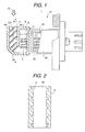
- Fig. 1 is a partial section of the first embodiment of a thermal type flow rate measuring device according to the present invention.
- auxiliary passage 6 On the inner periphery of the auxiliary passage 6 in the vicinity of an inlet portion 7 through which fluid is introduced into the auxiliary passage, a plurality of grooves 2 or beam-like ridges 3 extending oblique in relation to a flow axis 10 of the fluid at an angle greater than 0° and smaller than 90° in clockwise direction (tilted from the inner side surface 6b to the outer side surface 6a of the auxiliary passage 6).
- the reference numeral 5 denotes a temperature measuring resistor
- 33 denotes a cover.
- Fig. 2 is a section of the auxiliary passage 6 of Fig. 1, as taken along line A - A.
- the auxiliary passage 6 is formed with a material, such as PBT resin containing 30% of glass fiber.
- a thickness of the peripheral wall of the auxiliary passage 6 is about 2 mm
- a width of the groove 2 is in a range about 0.3 mm to about 2 mm
- a depth of the groove 2 is in a range about 0.2 mm to about 1 mm.
- the height of the beam-like ridge 3 can be greater than or equal to 1 mm.
- Figs. 4(a), 4(b) and 4(c) are illustrations showing a manner of primary movement of water droplet 21 when the grooves 2 or the beam-like ridges 3 in the auxiliary passage 6
- Figs. 5(a), 5(b) and 5(c) are illustrations showing a manner of movement of water droplet 21 adhering on the inner periphery of the auxiliary passage 6 of the construction shown in Fig. 4.
- Figs. 6(a), 6(b) and 6(c) are illustrations showing a manner of movement of water droplet 21 adhering on the inner periphery of the auxiliary passage 6 in the case where a plurality of grooves 2 or the beam-like ridges 3 are formed in the auxiliary passage 6.
- a part of the water droplet 21 passing through the auxiliary passage 6 adheres inner peripheral surface (side surface) in the vicinity of the inlet portion 7 of the auxiliary passage 6 between outer side surface 6a and inner side surface 6b. Then, adhered water droplet 21 moves along the side surface as pushed by flow 10 of the fluid. At this time, size of the water droplet 21 is less than or equal to 1 mm in diameter.
- the water droplet 21 adheres on the side surface of the auxiliary passage 6 similarly to Fig. 5(a). However, as shown in Fig. 6(b), adhered water droplet 21 contact with a plurality of grooves 2 or a plurality of beam-like ridges 3 and is captured in the grooves 2 or the beam-like ridges 3 by surface tension and is moved along the grooves 2 or the beam-like ridges 3 to the side wall or the outer side periphery 6a on the side where large centrifugal force generated by flow 10 of the fluid in the auxiliary passage 6.
- a plurality of grooves or a plurality of ridges may also be formed to tilt toward the inner peripheral surface where the water droplets concentrate in the auxiliary passage as actually flowing the water droplets. Then, comparable effect may be obtained.
- water droplet, oil droplet or the like may generally defined as liquid body.
- single bent groove 2 is employed,
- the single bent groove of zigzag pattern may achieve substantially the same function as the former embodiment, Therefore, single groove as bent in the shown pattern or the like may fall within the scope defined by the wording "plurality of grooves".
- the fifth embodiment shown in Fig. 11 is formed with a plurality of tilted grooves 2 oblique relative to the flow axis of the fluid, on the inner periphery of the U-shaped auxiliary passage 6. Also, on downstream side ends of the grooves 2, water drainage through holes 9 are formed.
- the capturing means of water droplet 21 is the grooves 2, and discharging means is the through holes 9 formed at the downstream portion of the grooves.
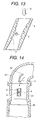
- Fig. 12 is a partial section of the sixth embodiment of the thermal type flow rate measuring device 1 according to the present invention
- Fig. 13 is a section taken along line C - C of Fig. 12.
- the main passages 31 and 31a is bent at a position in the vicinity of a site where the auxiliary passage 6 is mounted.
- a plurality of grooves 2 or a plurality of beam-like ridges 3 are formed on the inner periphery of the bent main passage 31a. Water droplets penetrating into the main passage 31a adhere on the inner periphery in the vicinity of a bent portion of the main passage 31a by inertia effect.
- adhered water droplet is captured by a plurality of grooves or a plurality of beam-like ridges to prevent growth of water droplet to reduce splashing of water droplet to penetrate into the auxiliary passage 6.
- an air cleaner 102, a body 105, a duct 106, a throttle angle sensor 107, an idle air control valve 108, a throttle body 109 are assembled with an intake manifold 110 for integration to form an air intake passage.
- An intake air 101 to the engine is detected flow rate by the thermal type flow rate sensor 1 according to the present invention while passing through the air intake passage or through a bypass passage.
- the detected flow rate signal is input to a control unit 11 in a form of voltage, frequency or the like to be used for controlling combustion portion and sub-system thereof constituted of an injector 112, a revolution speed sensor 113, an engine cylinder 114, an exhaust manifold 113, a gas 116, an oxygen concentration sensor 117.
- thermal type flow rate measuring device for controlling the combustion portion and sub-system, adhesion of water droplets, oil droplets and so forth on the sensor element can be prevented to permit accurate measurement of intake air flow rate to improve precision of engine control.
- the present invention is constructed by forming a capturing means for a liquid, such as water droplet, oil droplet or the like in the auxiliary passage or the main passage, and by discharging the captured liquid via a passage separated from the flow rate detecting sensor element, adhesion of the liquid, such as water droplet or the like on the flow rate detecting sensor element is successfully prevented to provide thermal type flow rate measuring device with high reliability.
- a liquid such as water droplet, oil droplet or the like
Landscapes
- Physics & Mathematics (AREA)
- Fluid Mechanics (AREA)
- General Physics & Mathematics (AREA)
- Measuring Volume Flow (AREA)
Abstract
Description
a liquid capturing means and/or discharging means being provided on an inner periphery of the auxiliary passage.
Claims (12)
- A thermal type flow rate measuring device comprising:an auxiliary passage (6) defined within a main passage (31) for introducing a part of fluid flowing through said main passage (31);a sensor (4) disposed within said auxiliary passage (6) for detecting flow rate of the fluid; andcapturing means formed on an inner periphery of said auxiliary passage (6) for capturing liquid contained in said fluid and transferring the captured liquid.
- A thermal type flow rate measuring device as set forth in claim 1, which further comprises discharging means for discharging the liquid captured by said capturing means out of said auxiliary passage (6).
- A thermal type flow rate measuring device as set forth in claim 2, wherein said capturing means or said capturing means and said discharge means is formed with one of a plurality of grooves (2), a plurality of beam-like ridges (3) and a combination of a plurality of grooves (2) and a plurality of beam-like ridges (3), said captured liquid is transferred along said one of a plurality of grooves (2), a plurality of beam-like ridges (3) and a combination of a plurality of grooves (2) and a plurality of beam-like ridges (3).
- A thermal type flow rate measuring device as set forth in claim 3, wherein a plurality of grooves (2), a plurality of beam-like ridges (3) and a combination of a plurality of grooves (2) and a plurality of beam-like ridges (3) extends from upstream side to downstream side in said auxiliary passage (6) in a manner directed from portions on the inner periphery of said auxiliary passage (6) where liquid passing through said auxiliary passage (6) is hardly concentrated to portions on the inner periphery of said auxiliary passage (6) where liquid passing through said auxiliary passage (6) is easily concentrated.
- A thermal type flow rate measuring device as set forth in claim 3, wherein a plurality of grooves (2), a plurality of beam-like ridges (3) and a combination of a plurality of grooves (2) and a plurality of beam-like ridges (3) extends from upstream side to downstream side in said auxiliary passage (6) in a manner directed from portions of the inner periphery of said auxiliary passage (6) where centrifugal to be applied is small to portions of the inner periphery of said auxiliary passage (6) where centrifugal force to be applied is large.
- A thermal type flow rate measuring device as set forth in claim 3, wherein a plurality of grooves (2), a plurality of beam-like ridges (3) and a combination of a plurality of grooves (2) and a plurality of beam-like ridges (3) extend oblique relative to flow direction of the fluid.
- A thermal type flow rare measuring device as set forth in claim 2, wherein said capturing means (2, 3) and/or said discharge means have hydrophilic film formed on the inner periphery of said auxiliary passage (6) so that when the liquid adheres on the inner periphery of said auxiliary passage (6), a contact angle is less than or equal to 30° .
- A thermal type flow rate measuring device as set forth in claim 2, wherein said capturing means and said discharge means is a plurality of grooves (2), a plurality of beam-like ridges (3) and a combination of a plurality of grooves (2) and a plurality of beam-like ridges (3), and another groove (2a) coupled with a plurality of grooves (2), a plurality of beam-like ridges (3) and a combination of a plurality of grooves (2) and a plurality of beam-like ridges (3), extends from a portion of the inner periphery of said auxiliary passage in the vicinity of an inlet portion (7) of said auxiliary passage (6) and a portion of the inner periphery of said auxiliary passage (6) in the vicinity of an outlet portion (8) of said auxiliary passage (6).
- A thermal type flow rate control device as set forth in claim 2, said capturing means is a plurality of grooves (2) formed on the inner periphery of said auxiliary passage (6), and the inner periphery of said auxiliary passage (6) of the portions other than those formed said plurality of grooves (2) are provided water repellent characteristics so that when the liquid adheres on the inner periphery of said auxiliary passage (6), its contact angle thereof becomes greater than or equal to about 90° .
- A thermal type flow rate measuring device as set forth in claim 2, wherein said capturing means is a plurality of grooves (2) formed in the inner periphery of said auxiliary passage (6), and said discharge means is through holes (9) formed on at downstream side of said plurality of grooves (2) in communication with said grooves (2).
- A thermal type flow rate measuring device comprising:a sensor (1) provided within a main passage through which a fluid flows, for measuring flow rate of said fluid in said main passage (31, 31a);said main passage (31, 31a) being curved in the vicinity of an upstream side of said sensor (1); andcapturing means formed on an inner periphery of said main passage (31a) for capturing a liquid carried by said fluid.
- A thermal type flow rate measuring device in a vehicle control system including a thermal type flow rate control device, a control unit (11) for controlling a vehicle on the basis of the condition of vehicle detected by said thermal type flow rate measuring sensor (1), said thermal type flow rate measuring device including an auxiliary passage (6) introducing a part of fluid flowing through a main passage (31), and a sensor (4) for detecting flow rate of the fluid,
a liquid capturing means and/or discharging means being provided on an inner periphery of said auxiliary passage.
Priority Applications (1)
| Application Number | Priority Date | Filing Date | Title |
|---|---|---|---|
| EP08004284.9A EP1939593B1 (en) | 2001-02-28 | 2001-09-19 | Thermal air flow rate measuring device |
Applications Claiming Priority (2)
| Application Number | Priority Date | Filing Date | Title |
|---|---|---|---|
| JP2001054106A JP3782669B2 (en) | 2001-02-28 | 2001-02-28 | Thermal flow meter |
| JP2001054106 | 2001-02-28 |
Related Child Applications (1)
| Application Number | Title | Priority Date | Filing Date |
|---|---|---|---|
| EP08004284.9A Division EP1939593B1 (en) | 2001-02-28 | 2001-09-19 | Thermal air flow rate measuring device |
Publications (3)
| Publication Number | Publication Date |
|---|---|
| EP1236975A2 true EP1236975A2 (en) | 2002-09-04 |
| EP1236975A3 EP1236975A3 (en) | 2005-10-05 |
| EP1236975B1 EP1236975B1 (en) | 2008-05-07 |
Family
ID=18914487
Family Applications (2)
| Application Number | Title | Priority Date | Filing Date |
|---|---|---|---|
| EP01121771A Expired - Lifetime EP1236975B1 (en) | 2001-02-28 | 2001-09-19 | Thermal flow rate measuring device |
| EP08004284.9A Expired - Lifetime EP1939593B1 (en) | 2001-02-28 | 2001-09-19 | Thermal air flow rate measuring device |
Family Applications After (1)
| Application Number | Title | Priority Date | Filing Date |
|---|---|---|---|
| EP08004284.9A Expired - Lifetime EP1939593B1 (en) | 2001-02-28 | 2001-09-19 | Thermal air flow rate measuring device |
Country Status (4)
| Country | Link |
|---|---|
| US (2) | US6571621B2 (en) |
| EP (2) | EP1236975B1 (en) |
| JP (1) | JP3782669B2 (en) |
| DE (1) | DE60133877D1 (en) |
Cited By (5)
| Publication number | Priority date | Publication date | Assignee | Title |
|---|---|---|---|---|
| US7467546B2 (en) | 2001-07-18 | 2008-12-23 | Hitachi, Ltd. | Equipment for measuring gas flow rate |
| EP2056076A1 (en) * | 2007-10-31 | 2009-05-06 | Hitachi Ltd. | Heating resistor type air flow rate measuring device |
| US7752908B2 (en) | 2001-07-18 | 2010-07-13 | Hitachi, Ltd. | Equipment for measuring gas flow rate having an adjacent external surface protrusion |
| EP2107348A3 (en) * | 2008-03-31 | 2014-03-26 | Hitachi Ltd. | Thermal type flowmeter |
| EP3112818A1 (en) * | 2015-07-01 | 2017-01-04 | Iasset Ag | Respiratory flow sensor |
Families Citing this family (24)
| Publication number | Priority date | Publication date | Assignee | Title |
|---|---|---|---|---|
| JP3716163B2 (en) * | 2000-06-16 | 2005-11-16 | 株式会社日立製作所 | Air flow measurement device |
| JP3764860B2 (en) * | 2001-09-11 | 2006-04-12 | 株式会社日立製作所 | Flow measuring device |
| DE10246069A1 (en) * | 2002-10-02 | 2004-04-15 | Robert Bosch Gmbh | Device for determining at least one parameter of a medium flowing in a line |
| JP4073324B2 (en) * | 2003-01-24 | 2008-04-09 | 株式会社日立製作所 | Thermal flow meter |
| DE10356833A1 (en) * | 2003-12-05 | 2005-07-07 | Robert Bosch Gmbh | Air filter for combustion engines of vehicles with a flow deflection element to remove fluid drops from the air stream |
| JP4476287B2 (en) * | 2004-06-10 | 2010-06-09 | 株式会社山武 | Flowmeter |
| WO2006003717A1 (en) * | 2004-06-30 | 2006-01-12 | Hitachi, Ltd. | Air flow measurement device |
| JP4881554B2 (en) * | 2004-09-28 | 2012-02-22 | 日立オートモティブシステムズ株式会社 | Flow sensor |
| JP4909561B2 (en) * | 2005-10-19 | 2012-04-04 | 日立オートモティブシステムズ株式会社 | Heating resistor type air flow measuring device |
| JP2007285950A (en) * | 2006-04-19 | 2007-11-01 | Hitachi Ltd | Heating resistor type air flow measuring device |
| JP5049996B2 (en) * | 2009-03-31 | 2012-10-17 | 日立オートモティブシステムズ株式会社 | Thermal flow meter |
| US8549908B2 (en) * | 2010-06-17 | 2013-10-08 | Los Robles Advertising, Inc. | Thermal anemometer flow meter for the measurement of wet gas flow |
| JP5769076B2 (en) * | 2011-08-26 | 2015-08-26 | 三菱自動車工業株式会社 | Gas sensor wet prevention device |
| JP5675707B2 (en) * | 2012-06-15 | 2015-02-25 | 日立オートモティブシステムズ株式会社 | Thermal flow meter |
| JP6129601B2 (en) * | 2013-03-21 | 2017-05-17 | 日立オートモティブシステムズ株式会社 | Thermal flow meter |
| JP6096070B2 (en) * | 2013-06-20 | 2017-03-15 | 日立オートモティブシステムズ株式会社 | Manufacturing method of thermal flow meter |
| CN105829874B (en) * | 2013-12-10 | 2018-10-16 | 日立汽车系统株式会社 | Humidity measuring instrument |
| JP5791759B1 (en) | 2014-05-19 | 2015-10-07 | 三菱電機株式会社 | Flow measuring device |
| JP2016121544A (en) * | 2014-12-24 | 2016-07-07 | ダイハツ工業株式会社 | Intake manifold |
| JP6690899B2 (en) * | 2015-06-29 | 2020-04-28 | 株式会社デンソー | Air flow measuring device |
| WO2017056699A1 (en) * | 2015-09-30 | 2017-04-06 | 日立オートモティブシステムズ株式会社 | Physical quantity detection device |
| JP6289585B1 (en) * | 2016-10-25 | 2018-03-07 | 三菱電機株式会社 | Flow measuring device |
| JP7065207B2 (en) * | 2018-12-05 | 2022-05-11 | 日立Astemo株式会社 | Physical quantity measuring device |
| JP7347163B2 (en) * | 2019-11-28 | 2023-09-20 | トヨタ自動車株式会社 | Gas sensor water prevention structure |
Family Cites Families (20)
| Publication number | Priority date | Publication date | Assignee | Title |
|---|---|---|---|---|
| DE2900200A1 (en) * | 1979-01-04 | 1980-07-17 | Bosch Gmbh Robert | MEASURING PROBE WITH PROTECTIVE LAYER AND METHOD FOR PRODUCING A PROTECTIVE LAYER ON A MEASURING PROBE |
| JPS5826221A (en) * | 1981-08-10 | 1983-02-16 | Hitachi Ltd | Measuring device for flow rate of air in internal-combustion engine |
| US4571996A (en) * | 1984-08-10 | 1986-02-25 | Allied Corporation | Air flow sensor |
| GB8619277D0 (en) * | 1986-08-07 | 1986-09-17 | Cranfield Inst Of Tech | Jet pump |
| US4880078A (en) * | 1987-06-29 | 1989-11-14 | Honda Giken Kogyo Kabushiki Kaisha | Exhaust muffler |
| US4914947A (en) * | 1988-09-30 | 1990-04-10 | Honeywell Inc. | Sampling probe flow sensor |
| US5133647A (en) * | 1989-07-07 | 1992-07-28 | Ultra-Precision Manufacturing, Ltd. | Pulse damper |
| US4981035A (en) * | 1989-08-07 | 1991-01-01 | Siemens Automotive L.P. | Dust defelector for silicon mass airflow sensor |
| EP0441523B2 (en) * | 1990-02-07 | 2001-05-09 | Hitachi, Ltd. | Air flow rate measuring device for an internal combustion engine |
| JPH0749979B2 (en) | 1990-04-10 | 1995-05-31 | 株式会社日立製作所 | Hot wire air flow meter |
| US5249462A (en) * | 1991-07-09 | 1993-10-05 | Honeywell Inc. | Safe channel design for flow sensor chip microbridges |
| US5220830A (en) * | 1991-07-09 | 1993-06-22 | Honeywell Inc. | Compact gas flow meter using electronic microsensors |
| JP2851960B2 (en) * | 1991-12-24 | 1999-01-27 | 日本碍子株式会社 | Intake air amount measurement device for internal combustion engine |
| JPH09287991A (en) | 1996-04-25 | 1997-11-04 | Denso Corp | Air flow measuring device |
| JPH09304140A (en) | 1996-05-13 | 1997-11-28 | Hitachi Ltd | Air flow measuring device |
| DE19800573A1 (en) * | 1998-01-09 | 1999-07-15 | Bosch Gmbh Robert | Unit for measuring mass flow rate of air into engine inlet manifold |
| JP2000081347A (en) * | 1998-09-04 | 2000-03-21 | Hitachi Ltd | Thermal air flow element and thermal air flow meter |
| DE10009154A1 (en) * | 2000-02-26 | 2001-09-13 | Bosch Gmbh Robert | Mass flow rate sensing system for e.g. engine air inlet manifold, includes construction functioning as mechanical and acoustic impedance |
| US6786089B2 (en) * | 2002-03-28 | 2004-09-07 | Denso Corporation | Airflow meter |
| US7360414B2 (en) * | 2003-07-14 | 2008-04-22 | Robert Bosch Gmbh | Device for determining at least one parameter of a medium flowing in a conduit and having a separation opening in the bypass passage |
-
2001
- 2001-02-28 JP JP2001054106A patent/JP3782669B2/en not_active Expired - Lifetime
- 2001-09-14 US US09/951,967 patent/US6571621B2/en not_active Ceased
- 2001-09-19 DE DE60133877T patent/DE60133877D1/en not_active Expired - Lifetime
- 2001-09-19 EP EP01121771A patent/EP1236975B1/en not_active Expired - Lifetime
- 2001-09-19 EP EP08004284.9A patent/EP1939593B1/en not_active Expired - Lifetime
-
2005
- 2005-06-03 US US11/143,971 patent/USRE42529E1/en not_active Expired - Lifetime
Cited By (8)
| Publication number | Priority date | Publication date | Assignee | Title |
|---|---|---|---|---|
| US7467546B2 (en) | 2001-07-18 | 2008-12-23 | Hitachi, Ltd. | Equipment for measuring gas flow rate |
| US7752908B2 (en) | 2001-07-18 | 2010-07-13 | Hitachi, Ltd. | Equipment for measuring gas flow rate having an adjacent external surface protrusion |
| EP1418407B1 (en) * | 2001-07-18 | 2013-06-19 | Hitachi, Ltd. | Equipment for measuring gas flow rate |
| EP2056076A1 (en) * | 2007-10-31 | 2009-05-06 | Hitachi Ltd. | Heating resistor type air flow rate measuring device |
| US7963161B2 (en) | 2007-10-31 | 2011-06-21 | Hitachi, Ltd. | Heating resistor type air flow rate measuring device utilizing an auxiliary passage |
| EP2107348A3 (en) * | 2008-03-31 | 2014-03-26 | Hitachi Ltd. | Thermal type flowmeter |
| EP3112818A1 (en) * | 2015-07-01 | 2017-01-04 | Iasset Ag | Respiratory flow sensor |
| WO2017002091A1 (en) * | 2015-07-01 | 2017-01-05 | Iasset Ag | Respiratory flow sensor |
Also Published As
| Publication number | Publication date |
|---|---|
| US20020116995A1 (en) | 2002-08-29 |
| USRE42529E1 (en) | 2011-07-12 |
| JP2002257608A (en) | 2002-09-11 |
| EP1236975B1 (en) | 2008-05-07 |
| DE60133877D1 (en) | 2008-06-19 |
| EP1939593B1 (en) | 2020-05-06 |
| EP1236975A3 (en) | 2005-10-05 |
| EP1939593A3 (en) | 2012-11-21 |
| US6571621B2 (en) | 2003-06-03 |
| JP3782669B2 (en) | 2006-06-07 |
| EP1939593A2 (en) | 2008-07-02 |
Similar Documents
| Publication | Publication Date | Title |
|---|---|---|
| EP1236975B1 (en) | Thermal flow rate measuring device | |
| JP4669530B2 (en) | Measuring device for measuring the mass of a flowing medium flowing in a pipe | |
| JP3709373B2 (en) | Flow measuring device | |
| US7032446B2 (en) | Flowrate measuring device with improved flow introduction into sub-passage outlet | |
| US6647775B1 (en) | Device for measuring at least one parameter of a flowing medium | |
| US20120079879A1 (en) | Mass Air Flow Measurement Device | |
| US20080236248A1 (en) | Gas sensor | |
| US20120237402A1 (en) | Detection device | |
| US20030046977A1 (en) | Device for determining at least one parameter of a flowing medium | |
| JP3919829B2 (en) | Measuring device for measuring the mass of a medium flowing in a conduit | |
| US6973823B2 (en) | Device for determining at least one parameter of a medium flowing in a line | |
| JP4289691B2 (en) | Intake pipe pressure detection device | |
| JP2857787B2 (en) | Thermal air flow meter and internal combustion engine equipped with the flow meter | |
| EP1221593B1 (en) | Gas flow measurement device | |
| ZA200206052B (en) | Device for measuring air flow, comprising a device for separating foreign particles. | |
| JPH10293113A (en) | Oxygen sensor and its mounting passage structure | |
| US6840101B2 (en) | Device for determining at least one parameter of a medium flowing in a line | |
| JP4659623B2 (en) | Thermal flow meter | |
| KR20020000886A (en) | Protective grating for a mass flow rate sensor in a channel of suctioned air | |
| KR20020001847A (en) | Device for determining at least one parameter of a flowing gas-liquid mixture or using a flow rectifier as a condensation trap or method for condensing liquid | |
| US20010006005A1 (en) | Flow rate measuring apparatus with a flow rate detector protecting structure | |
| JP4836179B2 (en) | Heating resistor type fluid flow measuring device | |
| JPH10141113A (en) | Intake pipe structure of internal combustion engine | |
| KR20020057344A (en) | Flow Measurement Device for Measuring Flow Rate and Flow Velocity | |
| JP2013044308A (en) | Device for preventing water from adhering to gas sensor |
Legal Events
| Date | Code | Title | Description |
|---|---|---|---|
| PUAI | Public reference made under article 153(3) epc to a published international application that has entered the european phase |
Free format text: ORIGINAL CODE: 0009012 |
|
| AK | Designated contracting states |
Kind code of ref document: A2 Designated state(s): AT BE CH CY DE DK ES FI FR GB GR IE IT LI LU MC NL PT SE TR |
|
| AX | Request for extension of the european patent |
Free format text: AL;LT;LV;MK;RO;SI |
|
| PUAL | Search report despatched |
Free format text: ORIGINAL CODE: 0009013 |
|
| AK | Designated contracting states |
Kind code of ref document: A3 Designated state(s): AT BE CH CY DE DK ES FI FR GB GR IE IT LI LU MC NL PT SE TR |
|
| AX | Request for extension of the european patent |
Extension state: AL LT LV MK RO SI |
|
| 17P | Request for examination filed |
Effective date: 20060124 |
|
| AKX | Designation fees paid |
Designated state(s): DE FR GB IT |
|
| 17Q | First examination report despatched |
Effective date: 20061017 |
|
| GRAP | Despatch of communication of intention to grant a patent |
Free format text: ORIGINAL CODE: EPIDOSNIGR1 |
|
| GRAS | Grant fee paid |
Free format text: ORIGINAL CODE: EPIDOSNIGR3 |
|
| GRAA | (expected) grant |
Free format text: ORIGINAL CODE: 0009210 |
|
| AK | Designated contracting states |
Kind code of ref document: B1 Designated state(s): DE FR GB IT |
|
| RAP1 | Party data changed (applicant data changed or rights of an application transferred) |
Owner name: HITACHI CAR ENGINEERING CO., LTD. Owner name: HITACHI, LTD. |
|
| REG | Reference to a national code |
Ref country code: GB Ref legal event code: FG4D |
|
| REF | Corresponds to: |
Ref document number: 60133877 Country of ref document: DE Date of ref document: 20080619 Kind code of ref document: P |
|
| PLBE | No opposition filed within time limit |
Free format text: ORIGINAL CODE: 0009261 |
|
| STAA | Information on the status of an ep patent application or granted ep patent |
Free format text: STATUS: NO OPPOSITION FILED WITHIN TIME LIMIT |
|
| 26N | No opposition filed |
Effective date: 20090210 |
|
| PGFP | Annual fee paid to national office [announced via postgrant information from national office to epo] |
Ref country code: FR Payment date: 20130910 Year of fee payment: 13 Ref country code: GB Payment date: 20130918 Year of fee payment: 13 |
|
| PGFP | Annual fee paid to national office [announced via postgrant information from national office to epo] |
Ref country code: IT Payment date: 20130913 Year of fee payment: 13 |
|
| GBPC | Gb: european patent ceased through non-payment of renewal fee |
Effective date: 20140919 |
|
| REG | Reference to a national code |
Ref country code: FR Ref legal event code: ST Effective date: 20150529 |
|
| PG25 | Lapsed in a contracting state [announced via postgrant information from national office to epo] |
Ref country code: GB Free format text: LAPSE BECAUSE OF NON-PAYMENT OF DUE FEES Effective date: 20140919 |
|
| PG25 | Lapsed in a contracting state [announced via postgrant information from national office to epo] |
Ref country code: IT Free format text: LAPSE BECAUSE OF NON-PAYMENT OF DUE FEES Effective date: 20140919 Ref country code: FR Free format text: LAPSE BECAUSE OF NON-PAYMENT OF DUE FEES Effective date: 20140930 |
|
| PGFP | Annual fee paid to national office [announced via postgrant information from national office to epo] |
Ref country code: DE Payment date: 20200909 Year of fee payment: 20 |
|
| REG | Reference to a national code |
Ref country code: DE Ref legal event code: R071 Ref document number: 60133877 Country of ref document: DE |