JP3919829B2 - Measuring device for measuring the mass of a medium flowing in a conduit - Google Patents
Measuring device for measuring the mass of a medium flowing in a conduit Download PDFInfo
- Publication number
- JP3919829B2 JP3919829B2 JP51263399A JP51263399A JP3919829B2 JP 3919829 B2 JP3919829 B2 JP 3919829B2 JP 51263399 A JP51263399 A JP 51263399A JP 51263399 A JP51263399 A JP 51263399A JP 3919829 B2 JP3919829 B2 JP 3919829B2
- Authority
- JP
- Japan
- Prior art keywords
- measuring
- passage
- conduit
- measuring device
- measurement
- Prior art date
- Legal status (The legal status is an assumption and is not a legal conclusion. Google has not performed a legal analysis and makes no representation as to the accuracy of the status listed.)
- Expired - Lifetime
Links
Images

Classifications
-
- G—PHYSICS
- G01—MEASURING; TESTING
- G01F—MEASURING VOLUME, VOLUME FLOW, MASS FLOW OR LIQUID LEVEL; METERING BY VOLUME
- G01F15/00—Details of, or accessories for, apparatus of groups G01F1/00 - G01F13/00 insofar as such details or appliances are not adapted to particular types of such apparatus
- G01F15/12—Cleaning arrangements; Filters
-
- G—PHYSICS
- G01—MEASURING; TESTING
- G01F—MEASURING VOLUME, VOLUME FLOW, MASS FLOW OR LIQUID LEVEL; METERING BY VOLUME
- G01F1/00—Measuring the volume flow or mass flow of fluid or fluent solid material wherein the fluid passes through a meter in a continuous flow
- G01F1/68—Measuring the volume flow or mass flow of fluid or fluent solid material wherein the fluid passes through a meter in a continuous flow by using thermal effects
- G01F1/684—Structural arrangements; Mounting of elements, e.g. in relation to fluid flow
- G01F1/6842—Structural arrangements; Mounting of elements, e.g. in relation to fluid flow with means for influencing the fluid flow
-
- G—PHYSICS
- G01—MEASURING; TESTING
- G01F—MEASURING VOLUME, VOLUME FLOW, MASS FLOW OR LIQUID LEVEL; METERING BY VOLUME
- G01F5/00—Measuring a proportion of the volume flow
Landscapes
- Physics & Mathematics (AREA)
- Fluid Mechanics (AREA)
- General Physics & Mathematics (AREA)
- Measuring Volume Flow (AREA)
Description
背景技術
本発明は、請求項1に規定した形式の、導管内を流動する媒体の質量を測定する測定装置に関する。
測定通路と変向ガイド通路とを測定モジュール内に組込んだ測定装置は、ドイツ連邦共和国特許第4407209号明細書に基づいてすでに公知である。前記測定通路は測定素子を收容し、かつ、入口ポートを起点として流動方向に次第に先細になっている。該測定通路には、S字形に形成された変向ガイド通路が接続し、該変向ガイド通路は方形の横断面プロフィールを有している。測定モジュールは差込み可能な構成部材として構成されている。測定モジュールの支持体部分は、測定すべき導管の壁に耐密的に挿嵌可能であり、かつ電子的評価回路装置を收容している。
測定素子としては、例えばドイツ連邦共和国特許出願公開第4338891号明細書に基づいて公知になっているような、マイクロメカニックな構成素子が特に適している。前記ドイツ連邦共和国特許出願公開第4338891号明細書に基づいて公知になっている測定素子では、2つの温度に敏感な抵抗が、仕切られたダイヤフラムに組込まれており、該ダイヤフラムは例えば酸化珪素又は窒化珪素から成り、かつ僅かな熱伝導率と僅かな比熱容量を有している。温度に敏感な両抵抗相互は珪素枠によって熱絶縁されている。第1の温度従変性抵抗が本来の測定センサとして働くのに対して、第2の温度従変性抵抗は流動媒体温度のためのセンサとして使用される。
測定素子に浮遊粒子が付着するのを減少させるために、吸込み通路内で空気量を測定する測定素子を、流動方向に対して所定角度だけ傾斜させることは、それ自体としてドイツ連邦共和国特許第3627465号明細書に基づいて公知である。更に当該刊行物に基づいて、同じく空気流中の浮遊粒子が付着するのを減少させるために、測定素子の、空気流に対面した方の端面と空気流から離反した方の端面に楔形の突起を設けることも公知である。楔形突起の形成は、珪素基板の異方性エッチングによって得られる。温度に敏感な測定素子の表面を、被測定媒体の流動方向に対して所定角度だけ傾斜させることは、ドイツ連邦共和国特許第3941330号明細書に基づいて公知である。測定素子が流動方向に対して極く僅かしか傾斜していない場合、或いは極端な例で流動方向に対して平行に方位づけられている場合、測定特性の角度従変性は比較的大きいが、測定素子の測定表面と被測定媒体の流動方向との傾斜角度が比較的大きい場合には測定特性の角度従変性は比較的僅かであるので、当該刊行物の思想によれば、媒体の流動方向と測定素子の測定表面との傾斜角度が20°〜60°の角度範囲内にある場合に、比較的確実な再現可能の測定結果が得られる。
しかしながら公知の測定装置は、流動媒体中で搬送される汚染粒子、特にダスト粒子が測定素子に衝突した場合、該測定素子が汚染粒子によって破壊されることがあるという欠点を有している。例えば前掲のドイツ連邦共和国特許出願公開第4338891号明細書に記載されているようなマイクロメカニックな構成部材が測定素子として使用される場合に殊に、汚染粒子は、比較的肉薄に形成されたダイヤフラムに衝突して該ダイヤフラムに永久損傷を及ぼすことがある。その結果、測定素子の摩耗は高められ、早期故障が生じることになる。更にまた油脂含有汚染粒子が、測定素子、特に測定素子のダイヤフラムに沈積することがあり、これは固体粒子、例えばダスト又は砂粒子のための粘着結合剤として働いて測定素子を永続的に汚染する。この汚染によって測定素子と流動媒体との間の熱結合作用が障害を受けるので、測定特性曲線のずれが生じ、必然的に測定誤差が惹起される。当該測定装置を内燃機関の吸気通路における吸気を検出するために使用する場合には、例えば燃料噴射弁の作動制御には誤差が生じ、従って燃料−空気の混合気の最適な調整は得られないので、内燃機関の排ガス値は、測定素子の汚染の増大に伴って劣化する。
公知の測定装置の更なる欠点は、被測定導管内で流れが脈動した場合には最適な測定精度が得られないことである。
発明の利点
請求項1の特徴部に記載した構成手段を備えた、導管内を流動する媒体の質量を測定する本発明の測定装置は、前記背景技術に対比して、流動媒体内で連行される汚染粒子による測定素子の負荷が大幅に回避され、少なくとも減少されるという利点を有している。特にマイクロメカニックな構成部材として構成された測定素子のダイヤフラムは、本発明の構成手段によって、流動媒体内で連行される汚染粒子との衝突から充分に防護されるので、測定素子の耐用寿命が著しく延長される。導管縦軸線に対する測定通路縦軸線の傾斜によって、測定通路内には、流動媒体内で連行される粒子の飛行経路に対して射影となる領域、つまり汚染粒子が全く侵入しない領域又は実質的に減少された数しか侵入しない領域が生じる。この領域内に測定素子を配置することによって、汚染粒子が測定素子に、特に該測定素子の薄肉の損傷し易いダイヤフラムに衝突するリスクは著しく減少する。更にまた測定素子に対する油脂含有汚染粒子の衝突が減少されるので、測定素子、特にマイクロメカニックな構成部材として構成された測定素子のダイヤフラム表面におけるダスト又はその他の固定粒子の付着による汚染が大幅に防止される。こうして特性曲線の変化が阻止され、かつ所期の測定結果の確実性が高められる。従って本発明の測定装置を内燃機関の吸気質量の検出のために使用することによって、内燃機関の排ガス値を改善することが可能である。
請求項2以降に記載した手段によって、請求項1に記載した測定装置の有利な構成と改良が可能である。
また出口ポートによって形成された測定装置の流出平面を導管縦軸線に対して所定角度だけ傾斜しておくのが特に有利である。この手段によって、被測定媒体の流れが脈動する場合の動特性が著しく改善され、かつ測定装置の測定通路及び変向ガイド通路を通流する媒体の流れが改善される。
測定素子は、測定通路内へ張出すプレートに固定されており、該プレートの上流側端面は、単数又は複数の傾斜面によって斜めに面取りされているのが有利である。この手段によって、プレートの上流側端面における汚染粒子の付着が低下される。その場合プレートは、ナイフエッジ状傾斜面の平面内に位置する横方向流動成分によって上流側端面に媒体を衝突させるように、測定通路内の主流動方向に対して方位づけられているのが有利である。前記横方向流動成分によって、傾斜面に付着する汚染粒子は、傾斜面に沿った力成分で負荷され、従って測定素子の損傷を受け易い領域から除去される。この自動クリーニング効果によって、測定素子の特性曲線安定性を付加的に改善することが可能になる。
同様に入口ポートにおける測定通路の制限壁の端面は、測定通路の制限壁の端面の平面内に位置する横方向流動成分によって前記制限壁の端面に媒体を衝突させるように、主流動方向に対して方位づけられているのが有利である。このようにすれば矢張り、端面に付着する汚染粒子が負荷して、自動クリーニング作用でもって除去する力成分が生じる。
図面
次に図面に基づいて本発明の実施例を詳説する。
第1図は第1実施例に相当する本発明の測定装置を一部断面して示した側面図である。
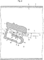
第2図は第2実施例に相当する本発明の測定装置を一部断面して示した側面図である。
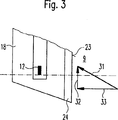
第3図は測定素子が固定されているプレートの上流側端面における流動関係の概略図である。
実施例の説明
第1図には、本発明の測定装置1の側面図が一部断面して図示されているが、該測定装置は流動媒体質量、特に内燃機関の吸気質量を測定するために働く。
測定装置1は、導管2内を流動する媒体の質量を検出する。導管2は、概略的に図示したにすぎないが、少なくとも測定装置1の領域内で導管縦軸線3に沿って延在している。該導管2は例えば内燃機関の吸気導管であり、該吸気導管を介して内燃機関は空気を周辺外気から吸込むことができる。第1図及び第2図に示した実施例では、媒体、例えば吸気は、右から左へ向かって導管2を通流する。導管2における流動方向は矢印6によって表示されている。
測定装置1は殊に、導管2内で半径方向に細長く延びた直方体の形状を有し、かつ殊に、導管2の周壁4から切欠かれた導管2の開口(図示せず)内へ例えば差込み可能に導入される。測定装置1の固定アーム5は、導管2の周壁4に測定装置1を固定するために使用される。その場合固定アーム5は、図示は省いたがカラー状の拡張部を有することができ、該拡張部は導管2の周壁4に対して密封されている。導管2の周壁4内へ差込み可能な差込みモジュールとして測定装置1を構成することによって、格別簡単な組立と保守が可能になる。有利な構成によれば固定アーム5内には、電子式評価回路装置が組込まれており、かつ導管2の周壁4から張出す固定アーム5の保持区分には、測定装置1の給電のため、及び測定装置1から得られる測定信号を取出すために適当な接続端子を設けておくことが可能である。
測定装置1は例えばプラスチック射出成形部品として合成樹脂から一体に製作することができる。測定装置1は、バイパス導管の形式で導管2の主流横断面8に対して平行に配置された流動通路7を有している。測定装置1の流動通路7は測定通路9へ区分され、該測定通路は、入口ポート10から流動方向で測定通路9に接続して、S字状に形成された変向ガイド通路11まで延びている。前記測定通路9は測定素子12を收容し、かつ流動方向で入口ポート10から変向ガイド通路11へ向かって徐々に先細になっている。これに対して変向ガイド通路11は、実質的に一様な方形の流動横断面を有しており、かつ測定装置1の流動通路7を通流する媒体を出口ポート13へ導く。隔壁14には、横断面で見て丸く面取りされた成形体15が接続し、該成形体は、沿面流動する媒体に極く僅かしか流動抵抗を与えない。出口ポート13は、導管2の周壁4の内側表面に対面している測定装置1の表面16に位置している。
測定素子12は、例えば前掲のドイツ連邦共和国特許出願公開第4338891号明細書で提案されるように、マイクロメカニックな構成部材として構成されているのが有利である。該測定素子は、それ自体公知のように少なくとも1つの、しかし有利には2つの、温度に敏感な抵抗素子を有しており、該抵抗素子は、例えば酸化珪素又は窒化珪素から成る誘電体ダイヤフラムに形成されている。抵抗素子相互は例えば珪素枠によって仕切られている。前記誘電体ダイヤフラムはこの場合、熱容量が極く僅かで熱伝導率が比較的僅かであるという利点を有しているので、測定素子の応答挙動が比較的短い。
測定素子12は、第1図及び第2図に示した有利な実施例では、珪素をベースとするプレート状支持体と、エッチング処理によって生じた複数の抵抗層を有し、前記プレート状支持体は、やはりエッチング処理によって生じた著しく僅かな肉厚のダイヤフラム状センサ領域を有している。前記抵抗層は少なくとも1つの温度従変性の測定抵抗と例えば1つの加熱抵抗を形成している。ダイヤフラムの中央に加熱抵抗が位置しているのが有利であり、該加熱抵抗は温度センサによって過剰温度に調節される。加熱抵抗によって形成された加熱領域の上流側と下流側に、加熱領域に対して対称的に配置された2つの測定抵抗が位置している。測定素子12の支持体は、例えば金属製収容体の切欠部内に該収容体と面整合するように収容されており、かつ例えば接着によって保持されている。前記収容体を以下、プレート18と呼ぶ。プレート18は測定通路9内に張出しているので、測定素子12をめぐって、測定装置1の流動通路7を通流する媒体が流れる。
本発明によれば、測定通路9の中心を通って延びる測定通路縦軸線19は導管縦軸線3に対して規定の角度αだけ傾斜されている。測定通路9はこの手段によって、測定通路9の入口ポート10の、導管縦軸線3に沿った平行投影の外側に位置する射影領域20を有している。第1図及び第2図では射影領域は点線21の上側に位置している。点線21は、導管2を通流する媒体内で連行される質量の比較的大きな汚染粒子の飛行経路を象徴的に表わしている。このような粒子は、測定素子12を損傷し、特にマイクロメカニックな構成部材として測定素子12を構成した場合には、該測定素子のダイヤフラムを著しく損傷することがある。しかしながら本発明の構成によって、測定素子12との有害な汚染粒子の衝突は効果的に防止される。測定素子12に損傷を与える汚染粒子は測定通路9の入口領域では、その比較的高い慣性質量に基づいて、測定通路縦軸線19の方へ向かっては無視できる程度にしか変向されない。従って有害汚染粒子の飛行経路は実質的に直線的に延びる。第1図及び第2図で点線21の上側を飛行する汚染粒子は、測定通路9の入口ポート10内へは流入せず、測定装置1の表面22に衝突する。第1図及び第2図で前記点線21より上位に位置する測定通路9の射影領域20内には、従って有害な汚染粒子は存在しない。更に本発明は、測定素子12をこの射影領域20内に配置することを提案する。測定素子12は測定通路9の中心近傍に配置されるのが有利である。それというのは、測定通路の中心近傍では最大流速が支配し、従って最大測定感度が得られるからである。
有利な実施形態では前記プレート18はその上流側端面23に、ナイフエッジ状に斜め面取りの施された少なくとも1つの傾斜面24を有している。前記のナイフエッジ状の傾斜面24は、上流側端面23の対向側にも形成されているのが有利であり、従ってプレート18は上流側端面23では主流動方向とは逆向きにナイフエッジの方式でテーパを成している。測定通路9の主流動方向は、第1図及び第2図に矢印25によって表示されている。ナイフエッジ状に斜め面取りを施すことによって得られる利点は、プレート18の汚染し易い前縁に流れ停滞点が形成されないので、該流れ停滞点で流動媒体が制動されて汚染粒子がプレート18の上流側端面23に沈積する不都合が決して生じないことである。特に測定素子12が珪素基板上にマイクロメカニックな構成部材として製作されている場合には、原則としてプレート18と測定素子12を一体に構成することも可能である。その場合、傾斜面24もしくは両面に設けられたナイフエッジ状傾斜面は、例えば珪素基板の異方性エッチング処理によって簡単に実現することができる。
第1図及び第2図に示した実施例では測定通路9、測定素子12を含むプレート18及び変向ガイド通路11はインテグラルな測定モジュールとして一体的に構成されている。従って図示の実施例では測定通路縦軸線19だけでなく、変向ガイド通路11を含めた測定モジュール全体が導管縦軸線3に対して規定の角度αだけ傾斜されている。それ故に慣用のかつ大量生産可能な測定モジュールを使用可能であるが、但し傾斜角度αだけは、測定素子12を測定通路9の射影領域20内に位置せしめるように調整されねばならない。導管縦軸線3に対して測定モジュール全体を傾斜させることによって、出口ポート13によって形成される流出平面17も導管縦軸線3に対して同時に傾斜される。従って出口ポート13は、導管2内に支配する媒体流の風下に位置し、すなわち媒体流の直撃を回避する側に位置している。これによって付加的な利点が得られる。それというのも測定装置1の流動通路7を通流する著しく均等な流れが生じ、かつ特に導管2内の媒体流が脈動する場合に、より大きな動特性が得られるからである。導管2内で、矢印6によって示した流動方向とは逆向きの逆流が発生する場合には、出口ポート13は、逆流に対面した方の側に位置し、かつ逆流のための入口ポートとして役立つので、このような逆流も測定装置1によって原則的に捕捉される。
第2図には、第1図に示した実施例に対して僅かに変化された第2実施例が図示されている。すでに述べた構成要素は同一の符号で表示されているので、その点に関する重複説明は省かれる。
第2図に示した実施例が、第1図に示した実施例と相違している点は先ず、固定アーム5が導管2内で軸方向成分なしに半径方向に導かれており、従って流動通路7の壁30が固定アーム5に対して屈曲されていることである。
別の相違点は、媒体が傾斜面24の平面内に位置する横方向運動成分をもって上流側端面23に衝突するように、プレート18の上流側端面23が、測定通路9内における媒体の主流動方向に対して方位づけられていることである。なお測定通路9内における媒体の主流動方向は第2図では矢印25によって示されている。プレート18の上流側端面23における流動関係の理解を助けるために、第3図では測定素子12を備えたプレート18が拡大して図示されている。プレート18の上流側端面23の流れ直撃領域における主流動方向は、測定通路縦軸線19に対して実質的に平行である。また主流動方向は第3図では矢印31によって示されている。プレート18の上流側端面23に衝突する場合、主流は、第3図において矢印32と33によって示した2つの流動ベクトル成分に分割される。その場合、矢印32は横方向流動成分を表わし、該横方向流動成分は傾斜面24の平面内に位置している。該横方向流動成分は、傾斜面24に付着する汚染粒子に対して、第3図では上向きの力成分を及ぼし、該力成分は汚染粒子を傾斜面25に沿って主流動方向31に対して横方向に運動させる。これによってナイフエッジ状の傾斜面24の自動クリーニング効果が生じる。それというのは傾斜面24に付着する汚染粒子が横方向流動成分によって、剥離されて除去されるか、或いはナイフエッジ状の傾斜面24の側方終端域、つまり汚染粒子が測定素子12の特性曲線にいかなる実質的な影響も及ぼさない終端域へ押しやられるからである。従ってプレート12に付着する汚染粒子による測定素子12の特性曲線のずれは、この手段によって更に減少され、かつ本発明の測定装置1の確実性と測定精度は更に向上される。
第2図に示した実施例ではプレート18は、測定通路9内におけるプレート18の傾斜角度が、導管縦軸線3に対して通路縦軸線19の占める傾斜角度αに等しくなるように測定通路9内で方位づけられている。
従ってプレート18の少なくとも上流側端面が、導管縦軸線3に関して半径方向で、もしくはこれに対して垂直に位置決めされている。しかしながら、これは必ず必要という訳ではない。むしろプレート18は測定通路9内で、角度αから偏位した角度だけ傾斜されていてもよいが、その場合測定通路9内におけるプレート18の最適傾斜角度は、媒体の流速、測定通路9の開口横断面積及びその他のパラメータに関連して最適化されねばならない。
入口ポート10では、ここでも汚染粒子の付着を充分に回避するために類似の手段が設けられている。測定通路9は、第2図の図平面に対して垂直に互いにずらされた2つの制限壁を有している。但し第2図では後部の制限壁35しか知見できない。該制限壁35は入口ポート10に端面34を有している。入口ポート10では、測定通路9の(図平面に対して垂直にずらされた)第2の制限壁に、相応の端面が形成されている。第2図に示した実施例では、制限壁35の端面34は、測定通路9の、矢印25で示した主流動方向に対して垂直には方位づけられていない。むしろ該端面34は、媒体が測定通路9の制限壁35の端面34に対して、該端面34の平面内に位置する横方向流動成分をもって衝突するように傾斜されている。これによって、プレート18に関して既に説明した自動クリーニング効果が得られ、かつ、端面34に付着している汚染粒子は剥離されて除去され、或いは少なくとも端面34に沿って該端面34の一方の端部に達するまでシフトされる。
本発明は図示の実施例に制限されるものではない。測定通路9及び変向ガイド通路7は、それが適当な適用例にとって効果的であるならば、別の態様で構成されていてもよい。本発明の測定装置1は、気相流動媒体の質量を測定するためにも、液相流動媒体の質量を測定するためにも適している。The invention relates to a measuring device for measuring the mass of a medium flowing in a conduit of the type defined in claim 1.
A measuring device incorporating a measuring channel and a turning guide channel in a measuring module is already known from DE 4407209. The measuring passage accommodates the measuring element and gradually tapers in the flow direction starting from the inlet port. The measuring passage is connected to a turning guide passage formed in an S-shape, and the turning guide passage has a rectangular cross-sectional profile. The measurement module is configured as a pluggable component. The support part of the measuring module can be tightly inserted into the wall of the conduit to be measured and contains an electronic evaluation circuit device.
As the measuring element, a micromechanical component is known which is known for example on the basis of DE 43 38 891 A1. In the measuring element known from DE 43 38 891, two temperature-sensitive resistors are incorporated in a partitioned diaphragm, for example silicon oxide or It consists of silicon nitride and has a slight thermal conductivity and a small specific heat capacity. Both resistances sensitive to temperature are thermally insulated by a silicon frame. The first temperature-dependent resistance acts as the original measurement sensor, whereas the second temperature-dependent resistance is used as a sensor for the fluid medium temperature.
In order to reduce the adhesion of airborne particles to the measuring element, the measuring element for measuring the amount of air in the suction passage is tilted by a certain angle with respect to the flow direction, as it is in German Patent No. 3627465. It is known on the basis of the specification. Further, according to the publication, in order to reduce the adhesion of airborne particles in the air flow, wedge-shaped projections on the end surface of the measuring element facing the air flow and the end surface away from the air flow are also provided. Is also known. Formation of the wedge-shaped projection is obtained by anisotropic etching of the silicon substrate. It is known on the basis of DE 39 41 330 that the surface of the measuring element sensitive to temperature is inclined by a predetermined angle with respect to the flow direction of the medium to be measured. If the measuring element is only slightly inclined with respect to the flow direction, or in the extreme case, it is oriented parallel to the flow direction, the angular dependence of the measurement characteristic is relatively large, but the measurement When the inclination angle between the measurement surface of the element and the flow direction of the medium to be measured is relatively large, the angular dependence of the measurement characteristics is relatively small. Therefore, according to the idea of the publication, the flow direction of the medium A relatively reliable and reproducible measurement result is obtained when the angle of inclination of the measuring element with respect to the measuring surface is in the range of 20 ° to 60 °.
However, the known measuring device has the disadvantage that if the contaminating particles, especially dust particles, carried in the fluid medium collide with the measuring element, the measuring element may be destroyed by the contaminating particles. For example, particularly when a micromechanical component as described in the above-mentioned German Patent Application No. 4338891 is used as a measuring element, the contaminant particles are formed as a relatively thin diaphragm. May cause permanent damage to the diaphragm. As a result, wear of the measuring element is increased and premature failure occurs. Furthermore, oil-containing contaminating particles can be deposited on the measuring element, in particular the diaphragm of the measuring element, which acts as an adhesive binder for solid particles, for example dust or sand particles, permanently contaminating the measuring element. . Due to this contamination, the thermal coupling action between the measuring element and the fluid medium is disturbed, so that a deviation of the measurement characteristic curve occurs, and a measurement error is inevitably caused. When the measuring device is used for detecting intake air in the intake passage of an internal combustion engine, for example, an error occurs in the operation control of the fuel injection valve, and therefore an optimal adjustment of the fuel-air mixture cannot be obtained. Therefore, the exhaust gas value of the internal combustion engine deteriorates with an increase in the contamination of the measuring element.
A further disadvantage of the known measuring device is that optimal measurement accuracy cannot be obtained if the flow pulsates in the conduit to be measured.
Advantages of the Invention A measuring device according to the invention for measuring the mass of a medium flowing in a conduit, comprising the means defined in the characterizing part of claim 1, is entrained in a flowing medium in contrast to the background art. This has the advantage that the load on the measuring element due to contaminating particles is largely avoided and at least reduced. In particular, the diaphragm of the measuring element configured as a micromechanical component is sufficiently protected from collision with contaminating particles entrained in the flow medium by the component means of the present invention, so that the service life of the measuring element is remarkably increased. Extended. Due to the inclination of the measurement channel longitudinal axis relative to the conduit longitudinal axis, the measurement channel is projected into the flight path of the particles entrained in the flow medium, i.e. the region where no contaminating particles enter or substantially reduced. An area that only enters the specified number is generated. By placing the measuring element in this region, the risk of contaminating particles hitting the measuring element, in particular the thin diaphragm of the measuring element, which is susceptible to damage, is significantly reduced. Furthermore, since the collision of oil-containing contaminated particles with the measuring element is reduced, contamination due to adhesion of dust or other fixed particles on the diaphragm surface of the measuring element, particularly the measuring element configured as a micromechanical component, is greatly prevented. Is done. In this way, the change of the characteristic curve is prevented and the certainty of the intended measurement result is increased. Therefore, it is possible to improve the exhaust gas value of the internal combustion engine by using the measuring device of the present invention for detecting the intake mass of the internal combustion engine.
Advantageous configurations and improvements of the measuring device described in claim 1 are possible by means described in the second and subsequent claims.
It is particularly advantageous to incline the outflow plane of the measuring device formed by the outlet port by a predetermined angle with respect to the longitudinal axis of the conduit. By this means, the dynamic characteristics when the flow of the medium to be measured pulsates is remarkably improved, and the flow of the medium flowing through the measurement passage and the direction guide passage of the measuring device is improved.
The measuring element is fixed to a plate extending into the measuring passage, and the upstream end face of the plate is advantageously chamfered obliquely by one or more inclined surfaces. By this means, the adhesion of contaminating particles on the upstream end face of the plate is reduced. In that case, the plate is advantageously oriented with respect to the main flow direction in the measuring channel so that the medium impinges on the upstream end face by a transverse flow component located in the plane of the knife-edge inclined surface. It is. By means of the lateral flow component, the contaminating particles adhering to the inclined surface are loaded with a force component along the inclined surface and are therefore removed from the area susceptible to damage to the measuring element. This automatic cleaning effect can additionally improve the characteristic curve stability of the measuring element.
Similarly, the end face of the restriction wall of the measurement passage at the inlet port is relative to the main flow direction so that the medium impinges on the end face of the restriction wall by a transverse flow component located in the plane of the end face of the restriction wall of the measurement passage. Are advantageously oriented. By doing so, the contaminated particles adhering to the arrow and the end face are loaded, and a force component to be removed by the automatic cleaning action is generated.
Next, embodiments of the present invention will be described in detail with reference to the drawings.
FIG. 1 is a side view partially showing a measuring apparatus according to the present invention corresponding to the first embodiment.
FIG. 2 is a side view showing a partial cross section of the measuring apparatus of the present invention corresponding to the second embodiment.
FIG. 3 is a schematic diagram of the flow relationship at the upstream end face of the plate on which the measuring element is fixed.
DESCRIPTION OF THE PREFERRED EMBODIMENTS FIG. 1 is a partially sectional side view of a measuring device 1 according to the present invention. This measuring device is used to measure the mass of a fluid medium, particularly the intake mass of an internal combustion engine. work.
The measuring device 1 detects the mass of the medium flowing in the
The measuring device 1 has in particular a rectangular parallelepiped shape extending radially in the
The measuring device 1 can be integrally manufactured from a synthetic resin, for example, as a plastic injection molded part. The measuring device 1 has a flow passage 7 arranged parallel to the main
The measuring
In the preferred embodiment shown in FIGS. 1 and 2, the measuring
According to the invention, the measurement passage
In an advantageous embodiment, the
In the embodiment shown in FIGS. 1 and 2, the
FIG. 2 shows a second embodiment which is slightly modified with respect to the embodiment shown in FIG. Since the constituent elements already described are denoted by the same reference numerals, the redundant explanation regarding this point is omitted.
The embodiment shown in FIG. 2 differs from the embodiment shown in FIG. 1 in that the fixed
Another difference is that the
In the embodiment shown in FIG. 2, the
Accordingly, at least the upstream end face of the
Again, similar means are provided at the
The invention is not limited to the embodiment shown. The
Claims (9)
流動媒体によって沿面を流動される測定素子(12)を備え、該測定素子が、前記導管(2)内に設けた測定通路(9)内に配置されており、該測定通路が、測定通路縦軸線(19)に沿って入口ポート(10)から変向ガイド通路(11)へ延びており、該変向ガイド通路が、前記導管(2)内に開口する出口ポート(13)に達しており、測定通路縦軸線(19)が、導管縦軸線(3)に対して規定角度(α)だけ傾斜されており、これに伴って測定通路(9)が、前記導管縦軸線(3)に沿った入口ポート(10)の平行投影図の外側に位置する射影領域(20)を有しており、かつ測定素子(12)が、前記測定通路(9)の射影領域(20)内に配置されている形式のものにおいて、
測定通路縦軸線(19)が、導管縦軸線(3)に対して次のように傾斜されており、つまり、流動媒体によって連行される汚染粒子の飛行経路が、導管縦軸線(3)に対して平行に延び、かつ入口ポート(10)と交差する直線(21)に沿って、測定通路(9)の射影領域(20)に侵入しないように、かつ汚染粒子が、実質的に前記直線(21)方向で真っ直ぐに通流して変向ガイド通路(11)に侵入するように、傾斜されていることを特徴とする、導管内を流動する媒体の質量を測定する測定装置。 A measuring device (1) for measuring the mass of a medium flowing in a conduit (2) along a longitudinal axis (3) of the conduit, in particular the intake mass of an internal combustion engine ,
A measuring element (12) that is flowed along the creeping surface by a fluid medium is provided, the measuring element being arranged in a measuring passage (9) provided in the conduit (2), the measuring passage being arranged vertically in the measuring passage. along the axis (19) extending from the inlet port (10) to the deflection guide passage (11), the displacement direction guide passage, has reached the outlet port (13) opening into the conduit (2) in The measurement passage longitudinal axis (19) is inclined by a specified angle (α) with respect to the conduit longitudinal axis (3), and accordingly the measurement passage (9) is along the conduit longitudinal axis (3). A projection area (20) located outside the parallel projection of the inlet port (10), and a measuring element (12) is arranged in the projection area (20) of the measurement passage (9). in those Zheng Ru format,
The measurement path longitudinal axis (19) is inclined with respect to the conduit longitudinal axis (3) as follows, i.e. the flight path of the pollutant particles entrained by the flow medium is relative to the conduit longitudinal axis (3): Along the straight line (21) that extends in parallel and intersects the inlet port (10) so that it does not enter the projection region (20) of the measurement passage (9) and that the contaminating particles are substantially 21) A measuring device for measuring the mass of a medium flowing in a conduit, wherein the measuring device is inclined so as to flow straight in the direction and enter the turning guide passage (11) .
Applications Claiming Priority (3)
| Application Number | Priority Date | Filing Date | Title |
|---|---|---|---|
| DE19735891A DE19735891A1 (en) | 1997-08-19 | 1997-08-19 | Device for measuring mass of medium flowing in pipe, especially air in IC engine induction system |
| DE19735891.8 | 1997-08-19 | ||
| PCT/DE1998/001364 WO1999009378A1 (en) | 1997-08-19 | 1998-05-16 | Device for measuring the volume of a medium flowing in a conduit |
Publications (2)
| Publication Number | Publication Date |
|---|---|
| JP2001504943A JP2001504943A (en) | 2001-04-10 |
| JP3919829B2 true JP3919829B2 (en) | 2007-05-30 |
Family
ID=7839398
Family Applications (1)
| Application Number | Title | Priority Date | Filing Date |
|---|---|---|---|
| JP51263399A Expired - Lifetime JP3919829B2 (en) | 1997-08-19 | 1998-05-16 | Measuring device for measuring the mass of a medium flowing in a conduit |
Country Status (5)
| Country | Link |
|---|---|
| US (1) | US6298720B1 (en) |
| EP (1) | EP0932820B1 (en) |
| JP (1) | JP3919829B2 (en) |
| DE (1) | DE19735891A1 (en) |
| WO (1) | WO1999009378A1 (en) |
Families Citing this family (13)
| Publication number | Priority date | Publication date | Assignee | Title |
|---|---|---|---|---|
| US6422070B2 (en) * | 1994-03-04 | 2002-07-23 | Robert Bosch Gmbh | Device for measuring the mass of a flowing medium |
| DE19927818C2 (en) * | 1999-06-18 | 2003-10-23 | Bosch Gmbh Robert | Device for measuring the mass of a flowing medium |
| DE10011709A1 (en) | 2000-03-10 | 2001-09-13 | Bosch Gmbh Robert | Air flow measurement device for internal combustion engine, has protective grating with side wall inclined at preset angle with respect to air flow directions |
| DE10019149B4 (en) * | 2000-04-18 | 2007-06-06 | Robert Bosch Gmbh | Device for determining at least one parameter of a flowing medium |
| DE10036290A1 (en) * | 2000-07-26 | 2002-02-07 | Bosch Gmbh Robert | Device for determining at least one parameter of a flowing medium |
| DE10042400A1 (en) | 2000-08-30 | 2002-03-14 | Bosch Gmbh Robert | Device for determining at least one parameter of a flowing medium |
| DE10135142A1 (en) * | 2001-04-20 | 2002-10-31 | Bosch Gmbh Robert | Device for determining at least one parameter of a medium flowing in a line |
| JP3709385B2 (en) * | 2002-07-01 | 2005-10-26 | 株式会社日立製作所 | Gas flow measuring device for internal combustion engine |
| JP4034251B2 (en) * | 2003-09-26 | 2008-01-16 | 株式会社ケーヒン | Intake device for internal combustion engine and method for measuring intake air amount |
| JP4404104B2 (en) * | 2007-03-29 | 2010-01-27 | 株式会社デンソー | Air flow measurement device |
| JP5183164B2 (en) * | 2007-11-19 | 2013-04-17 | 日立オートモティブシステムズ株式会社 | Flow measuring device |
| DE102012100087A1 (en) * | 2012-01-05 | 2013-07-11 | Pierburg Gmbh | Device for determining a gas mass flow |
| JP6915098B2 (en) * | 2018-01-22 | 2021-08-04 | 日立Astemo株式会社 | Thermal flow meter |
Family Cites Families (9)
| Publication number | Priority date | Publication date | Assignee | Title |
|---|---|---|---|---|
| JPS62123318A (en) | 1985-08-13 | 1987-06-04 | Nippon Soken Inc | Direct heat type flow rate sensor |
| DE3636930A1 (en) * | 1986-10-30 | 1988-05-05 | May Michael G | Method and device for sensing the through-flows of fluids |
| JPH0620974Y2 (en) | 1988-12-16 | 1994-06-01 | 三菱電機株式会社 | Thermal flow sensor |
| DE3922489A1 (en) * | 1989-07-08 | 1991-01-17 | Bosch Gmbh Robert | AIR MEASURING DEVICE |
| US4981035A (en) * | 1989-08-07 | 1991-01-01 | Siemens Automotive L.P. | Dust defelector for silicon mass airflow sensor |
| DE4338891A1 (en) | 1993-02-25 | 1994-09-01 | Bosch Gmbh Robert | Mass flow sensor |
| DE4407209C2 (en) * | 1994-03-04 | 1996-10-17 | Bosch Gmbh Robert | Device for measuring the mass of a medium flowing in a line |
| US5537870A (en) * | 1994-10-03 | 1996-07-23 | Ford Motor Company | Contaminant free backflow reducing insert for mass air flow sensors |
| DE19547915A1 (en) * | 1995-12-21 | 1997-06-26 | Bosch Gmbh Robert | Device for measuring the mass of a flowing medium |
-
1997
- 1997-08-19 DE DE19735891A patent/DE19735891A1/en not_active Withdrawn
-
1998
- 1998-05-16 US US09/284,603 patent/US6298720B1/en not_active Expired - Lifetime
- 1998-05-16 WO PCT/DE1998/001364 patent/WO1999009378A1/en not_active Ceased
- 1998-05-16 JP JP51263399A patent/JP3919829B2/en not_active Expired - Lifetime
- 1998-05-16 EP EP98934742.2A patent/EP0932820B1/en not_active Expired - Lifetime
Also Published As
| Publication number | Publication date |
|---|---|
| EP0932820A1 (en) | 1999-08-04 |
| EP0932820B1 (en) | 2016-02-24 |
| JP2001504943A (en) | 2001-04-10 |
| US6298720B1 (en) | 2001-10-09 |
| DE19735891A1 (en) | 1999-02-25 |
| WO1999009378A1 (en) | 1999-02-25 |
Similar Documents
| Publication | Publication Date | Title |
|---|---|---|
| JP4169802B2 (en) | Measuring device for measuring the mass of a flowing medium flowing in a pipe | |
| JP3919829B2 (en) | Measuring device for measuring the mass of a medium flowing in a conduit | |
| JP5049996B2 (en) | Thermal flow meter | |
| KR100402728B1 (en) | Heating resistance flow measurement device and internal combustion engine control system using the same | |
| US6851311B2 (en) | Thermal-type flow meter with bypass passage | |
| JP3782669B2 (en) | Thermal flow meter | |
| JP4161077B2 (en) | Flow measuring device | |
| JP4929335B2 (en) | Thermal flow meter | |
| US7032446B2 (en) | Flowrate measuring device with improved flow introduction into sub-passage outlet | |
| JP2004505235A (en) | Apparatus for measuring at least one parameter of a flowing medium | |
| US6675644B2 (en) | Thermo-sensitive flow rate sensor | |
| JP4169803B2 (en) | Measuring device for measuring the mass of a flowing medium | |
| US6868722B2 (en) | Air flow rate measuring apparatus | |
| KR102002657B1 (en) | Method for operating an air mass sensor | |
| JP2001004420A (en) | Flow and flow velocity measuring device | |
| EP1221593B1 (en) | Gas flow measurement device | |
| US6474154B2 (en) | Flow measurement device for measuring flow rate and flow velocity | |
| JP3671393B2 (en) | Thermal flow sensor | |
| US20010006005A1 (en) | Flow rate measuring apparatus with a flow rate detector protecting structure | |
| KR20020033492A (en) | Heat-sensitive flow rate sensor | |
| WO2020202722A1 (en) | Physical-quantity detection device | |
| JP2001255188A (en) | Flow and flow velocity measuring device | |
| JP6674917B2 (en) | Thermal flow meter | |
| JP2004029033A (en) | Flow and flow velocity measuring device | |
| KR20020057344A (en) | Flow Measurement Device for Measuring Flow Rate and Flow Velocity |
Legal Events
| Date | Code | Title | Description |
|---|---|---|---|
| A621 | Written request for application examination |
Free format text: JAPANESE INTERMEDIATE CODE: A621 Effective date: 20050516 |
|
| A131 | Notification of reasons for refusal |
Free format text: JAPANESE INTERMEDIATE CODE: A131 Effective date: 20060425 |
|
| A601 | Written request for extension of time |
Free format text: JAPANESE INTERMEDIATE CODE: A601 Effective date: 20060724 |
|
| A602 | Written permission of extension of time |
Free format text: JAPANESE INTERMEDIATE CODE: A602 Effective date: 20060911 |
|
| A521 | Request for written amendment filed |
Free format text: JAPANESE INTERMEDIATE CODE: A523 Effective date: 20061020 |
|
| TRDD | Decision of grant or rejection written | ||
| A01 | Written decision to grant a patent or to grant a registration (utility model) |
Free format text: JAPANESE INTERMEDIATE CODE: A01 Effective date: 20070116 |
|
| A61 | First payment of annual fees (during grant procedure) |
Free format text: JAPANESE INTERMEDIATE CODE: A61 Effective date: 20070214 |
|
| R150 | Certificate of patent or registration of utility model |
Free format text: JAPANESE INTERMEDIATE CODE: R150 |
|
| FPAY | Renewal fee payment (event date is renewal date of database) |
Free format text: PAYMENT UNTIL: 20110223 Year of fee payment: 4 |
|
| FPAY | Renewal fee payment (event date is renewal date of database) |
Free format text: PAYMENT UNTIL: 20110223 Year of fee payment: 4 |
|
| FPAY | Renewal fee payment (event date is renewal date of database) |
Free format text: PAYMENT UNTIL: 20120223 Year of fee payment: 5 |
|
| FPAY | Renewal fee payment (event date is renewal date of database) |
Free format text: PAYMENT UNTIL: 20130223 Year of fee payment: 6 |
|
| FPAY | Renewal fee payment (event date is renewal date of database) |
Free format text: PAYMENT UNTIL: 20140223 Year of fee payment: 7 |
|
| R250 | Receipt of annual fees |
Free format text: JAPANESE INTERMEDIATE CODE: R250 |
|
| R250 | Receipt of annual fees |
Free format text: JAPANESE INTERMEDIATE CODE: R250 |
|
| R250 | Receipt of annual fees |
Free format text: JAPANESE INTERMEDIATE CODE: R250 |
|
| R250 | Receipt of annual fees |
Free format text: JAPANESE INTERMEDIATE CODE: R250 |
|
| R250 | Receipt of annual fees |
Free format text: JAPANESE INTERMEDIATE CODE: R250 |
|
| EXPY | Cancellation because of completion of term |