EP1236895A1 - Electromagnetically operated pump - Google Patents
Electromagnetically operated pump Download PDFInfo
- Publication number
- EP1236895A1 EP1236895A1 EP02004697A EP02004697A EP1236895A1 EP 1236895 A1 EP1236895 A1 EP 1236895A1 EP 02004697 A EP02004697 A EP 02004697A EP 02004697 A EP02004697 A EP 02004697A EP 1236895 A1 EP1236895 A1 EP 1236895A1
- Authority
- EP
- European Patent Office
- Prior art keywords
- cylinder
- casing
- piston element
- oil
- chamber
- Prior art date
- Legal status (The legal status is an assumption and is not a legal conclusion. Google has not performed a legal analysis and makes no representation as to the accuracy of the status listed.)
- Granted
Links
- 238000005086 pumping Methods 0.000 claims abstract description 10
- 230000002093 peripheral effect Effects 0.000 claims abstract description 5
- 238000002485 combustion reaction Methods 0.000 claims abstract description 4
- 238000004519 manufacturing process Methods 0.000 description 1
- 238000000034 method Methods 0.000 description 1
- 238000011144 upstream manufacturing Methods 0.000 description 1
Images
Classifications
-
- F—MECHANICAL ENGINEERING; LIGHTING; HEATING; WEAPONS; BLASTING
- F04—POSITIVE - DISPLACEMENT MACHINES FOR LIQUIDS; PUMPS FOR LIQUIDS OR ELASTIC FLUIDS
- F04B—POSITIVE-DISPLACEMENT MACHINES FOR LIQUIDS; PUMPS
- F04B17/00—Pumps characterised by combination with, or adaptation to, specific driving engines or motors
- F04B17/03—Pumps characterised by combination with, or adaptation to, specific driving engines or motors driven by electric motors
- F04B17/04—Pumps characterised by combination with, or adaptation to, specific driving engines or motors driven by electric motors using solenoids
- F04B17/046—Pumps characterised by combination with, or adaptation to, specific driving engines or motors driven by electric motors using solenoids the fluid flowing through the moving part of the motor
-
- F—MECHANICAL ENGINEERING; LIGHTING; HEATING; WEAPONS; BLASTING
- F01—MACHINES OR ENGINES IN GENERAL; ENGINE PLANTS IN GENERAL; STEAM ENGINES
- F01M—LUBRICATING OF MACHINES OR ENGINES IN GENERAL; LUBRICATING INTERNAL COMBUSTION ENGINES; CRANKCASE VENTILATING
- F01M1/00—Pressure lubrication
- F01M1/02—Pressure lubrication using lubricating pumps
-
- F—MECHANICAL ENGINEERING; LIGHTING; HEATING; WEAPONS; BLASTING
- F01—MACHINES OR ENGINES IN GENERAL; ENGINE PLANTS IN GENERAL; STEAM ENGINES
- F01M—LUBRICATING OF MACHINES OR ENGINES IN GENERAL; LUBRICATING INTERNAL COMBUSTION ENGINES; CRANKCASE VENTILATING
- F01M3/00—Lubrication specially adapted for engines with crankcase compression of fuel-air mixture or for other engines in which lubricant is contained in fuel, combustion air, or fuel-air mixture
- F01M3/02—Lubrication specially adapted for engines with crankcase compression of fuel-air mixture or for other engines in which lubricant is contained in fuel, combustion air, or fuel-air mixture with variable proportion of lubricant to fuel, lubricant to air, or lubricant to fuel-air-mixture
-
- F—MECHANICAL ENGINEERING; LIGHTING; HEATING; WEAPONS; BLASTING
- F02—COMBUSTION ENGINES; HOT-GAS OR COMBUSTION-PRODUCT ENGINE PLANTS
- F02B—INTERNAL-COMBUSTION PISTON ENGINES; COMBUSTION ENGINES IN GENERAL
- F02B75/00—Other engines
- F02B75/02—Engines characterised by their cycles, e.g. six-stroke
- F02B2075/022—Engines characterised by their cycles, e.g. six-stroke having less than six strokes per cycle
- F02B2075/025—Engines characterised by their cycles, e.g. six-stroke having less than six strokes per cycle two
Definitions
- the present invention concerns an electromagnetically operated pump for the precise and controlled feeding of oil to two-stroke internal-combustion engines.
- the present invention concerns a pump of this type, with the object to improve its characteristics as far as structural simplicity, and metering precision and easiness, all being very important in view of the special use for which said pump is intended.
- the pump according to the invention - comprising in a casing: a cylinder; a piston element with a through pipe, axially movable in said cylinder; an electromagnetic coil external to the cylinder, to control the movements of the piston element against the action of spring means; a pumping and metering chamber for the oil to be fed, at one end of the cylinder; and valve means housed in said casing, close to said end, one of said means cooperating with said piston element - is characterized in that the stroke of the piston element is limited, on one side, by the plane surface of the casing onto which abuts the cylinder in correspondence of said chamber and, on the other side, by the inner surface of a cup bearing, with a projecting peripheral edge thereof, onto the end of the cylinder opposite to that of the chamber, stout spring means being interposed between said cup and the casing to stop the cylinder therein.
- the pump according to the invention comprises a casing 1, containing a cylinder 2 and a piston element 3, axially movable into the cylinder 2 and crossed by a pipe 4 connected with branches 5 and 6 - for oil inlet and outlet respectively - of the casing 1.
- a chamber 7 for pumping the oil to be fed delimited by the plane surface 8 of the casing 1, onto which bears the cylinder 2, and by the bottom end 9 of the piston element 3.
- an electromagnetic coil 10 fed with pulse current in strict correlation with the running of the two-stroke engine to be equipped with the pump.
- said coil 10 When energized, said coil 10 controls the movements of the piston element 3 towards the chamber 7, against the action of a spring 11 which acts in an opposite sense when the coil 10 is de-energized.
- Two ball valves 12, 13, are provided in the casing 1 close to the oil pumping chamber 7, the first of said valves cooperating with the bottom end 9 of the piston element 3, in correspondence of the outlet of the pipe 4.
- the valve 12 when the piston element 3 is moved by the electromagnetic coil 10, the valve 12 is closed while the valve 13 opens; viceversa, the valve 13 closes when the piston element 3 is moved by the spring 11 and while the valve 12 opens.
- an abutment 14 is formed on the piston element 3, close to the end opposite to the bottom end 9, said abutment 14 being apt to cooperate with the inner surface 15 of a cup 16, apt to stop the cylinder 2 into the casing 1.
- Said cup 16 bears in fact with its projecting peripheral edge 17 onto said cylinder 2 and is pressed against the same by a stout Belleville spring 18 engaging the plane surface 19 of the casing 1.
- the stroke of the piston element 3 into the cylinder 2 is thereby limited by the cooperation, on one side, between the abutment 14 and the inner surface 15 of the cup 16, and on the other side, between the bottom end 9 of the piston element 3 and the plane surface 8 of the casing 1.
- Said stroke determines the capacity (or volume) of the pumping chamber 7 and the metering of the oil to be fed.
- the figure of the accompanying drawing illustrates the pump according to the invention with the chamber 7 full of oil, the piston element 3 having its bottom end 9 spaced apart from the plane surface 8 of the casing 1 and the abutment 14 in contact with the inner surface 15 of the cup 16.
- the coil 10 When, in operation, the coil 10 is energized, the piston element 3 moves towards the plane surface 8 compressing the oil into the chamber 7, while the valve 12 closes the pipe 4 into which flows the oil let in through the branch 5.
- the oil pressure in the chamber 7 opens the valve 13 and the oil is fed through the branch 6 into the engine.
- the pumping of the oil is carried out by energizing the electromagnetic coil 10.
- the piston element 3 stops, with the chamber 7 empty, when the bottom element 9 thereof cooperates with the plane surface 8 of the casing 1.
- the pump described heretofore has a very simple structure and its working is very reliable; but, above all, it can be very easily adapted, at extremely reduced costs, to the most different requirements of capacity: the volume of the oil pumping and metering chamber 7 (namely, the amount of oil being fed at each piston stroke C) can in fact be easily adjusted, not only by acting on the axial position of the abutment 14 of the piston element 3, but also by simply replacing the existing cup 16 with a similar cup in which the projection of its peripheral edge 17 differs from the inner surface 15 thereof, or even by varying with a simple mechanical operation the projection in the cup 16 being used.
Landscapes
- Engineering & Computer Science (AREA)
- Mechanical Engineering (AREA)
- General Engineering & Computer Science (AREA)
- Physics & Mathematics (AREA)
- Fluid Mechanics (AREA)
- Electromagnetic Pumps, Or The Like (AREA)
- External Artificial Organs (AREA)
- Reciprocating Pumps (AREA)
Abstract
Description
- The present invention concerns an electromagnetically operated pump for the precise and controlled feeding of oil to two-stroke internal-combustion engines.
- There are known to be in technique many types of pumps allowing to feed two-stroke internal-combustion engines with precise and controlled amounts of oil, in strict correlation with the running of the actual engine. Amongst others, use is already being made since quite some time of electrically operated pumps, in which an electromagnetic coil controls the piston of a cylinder in axis therewith, against the action of a spring, so as to empty at each working cycle a pumping chamber thereof in which the oil to be fed is metered.
- The present invention concerns a pump of this type, with the object to improve its characteristics as far as structural simplicity, and metering precision and easiness, all being very important in view of the special use for which said pump is intended.
- To reach this object, the pump according to the invention - comprising in a casing: a cylinder; a piston element with a through pipe, axially movable in said cylinder; an electromagnetic coil external to the cylinder, to control the movements of the piston element against the action of spring means; a pumping and metering chamber for the oil to be fed, at one end of the cylinder; and valve means housed in said casing, close to said end, one of said means cooperating with said piston element - is characterized in that the stroke of the piston element is limited, on one side, by the plane surface of the casing onto which abuts the cylinder in correspondence of said chamber and, on the other side, by the inner surface of a cup bearing, with a projecting peripheral edge thereof, onto the end of the cylinder opposite to that of the chamber, stout spring means being interposed between said cup and the casing to stop the cylinder therein.
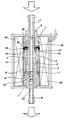
- The invention will now be described in further detail, with reference to the accompanying drawing, the only figure of which represents an axial section view of the improved pump according to the invention.
- As clearly shown on the drawing, the pump according to the invention comprises a casing 1, containing a
cylinder 2 and a piston element 3, axially movable into thecylinder 2 and crossed by apipe 4 connected withbranches 5 and 6 - for oil inlet and outlet respectively - of the casing 1. At one end of thecylinder 2 there is achamber 7 for pumping the oil to be fed, delimited by theplane surface 8 of the casing 1, onto which bears thecylinder 2, and by thebottom end 9 of the piston element 3. Externally to thecylinder 2 there is anelectromagnetic coil 10 fed with pulse current in strict correlation with the running of the two-stroke engine to be equipped with the pump. When energized, saidcoil 10 controls the movements of the piston element 3 towards thechamber 7, against the action of aspring 11 which acts in an opposite sense when thecoil 10 is de-energized. Twoball valves oil pumping chamber 7, the first of said valves cooperating with thebottom end 9 of the piston element 3, in correspondence of the outlet of thepipe 4. As better explained hereinafter, when the piston element 3 is moved by theelectromagnetic coil 10, thevalve 12 is closed while thevalve 13 opens; viceversa, thevalve 13 closes when the piston element 3 is moved by thespring 11 and while thevalve 12 opens. - According to the invention, an
abutment 14 is formed on the piston element 3, close to the end opposite to thebottom end 9, saidabutment 14 being apt to cooperate with theinner surface 15 of acup 16, apt to stop thecylinder 2 into the casing 1. Saidcup 16 bears in fact with its projectingperipheral edge 17 onto saidcylinder 2 and is pressed against the same by a stout Bellevillespring 18 engaging theplane surface 19 of the casing 1. The stroke of the piston element 3 into thecylinder 2 is thereby limited by the cooperation, on one side, between theabutment 14 and theinner surface 15 of thecup 16, and on the other side, between thebottom end 9 of the piston element 3 and theplane surface 8 of the casing 1. - Said stroke determines the capacity (or volume) of the
pumping chamber 7 and the metering of the oil to be fed. - The figure of the accompanying drawing illustrates the pump according to the invention with the
chamber 7 full of oil, the piston element 3 having itsbottom end 9 spaced apart from theplane surface 8 of the casing 1 and theabutment 14 in contact with theinner surface 15 of thecup 16. When, in operation, thecoil 10 is energized, the piston element 3 moves towards theplane surface 8 compressing the oil into thechamber 7, while thevalve 12 closes thepipe 4 into which flows the oil let in through thebranch 5. The oil pressure in thechamber 7 opens thevalve 13 and the oil is fed through thebranch 6 into the engine. Thus, the pumping of the oil is carried out by energizing theelectromagnetic coil 10. The piston element 3 stops, with thechamber 7 empty, when thebottom element 9 thereof cooperates with theplane surface 8 of the casing 1. When thecoil 10 is de-energized and its action ceases, thespring 11 causes the piston element 3 to return into its initial rest position; thevalve 13, no longer subject to pressure, closes while thevalve 12 opens, due to the difference between the pressure of the oil let in upstream of thebranch 5 and the oil pressure downstream thereof. The oil thus fills again thepumping chamber 7. - The pump described heretofore has a very simple structure and its working is very reliable; but, above all, it can be very easily adapted, at extremely reduced costs, to the most different requirements of capacity: the volume of the oil pumping and metering chamber 7 (namely, the amount of oil being fed at each piston stroke C) can in fact be easily adjusted, not only by acting on the axial position of the
abutment 14 of the piston element 3, but also by simply replacing the existingcup 16 with a similar cup in which the projection of itsperipheral edge 17 differs from theinner surface 15 thereof, or even by varying with a simple mechanical operation the projection in thecup 16 being used. It can be easily seen that, by keeping unchanged all the other components of the pump and by merely replacing thecup 16, a single pump - with specific characteristics according to the invention - can feed even considerably different oil capacities per piston stroke, and be thus immediately adapted to many different requirements and applications. The same can be done, with a simple mechanical operation, by reducing to different extents the starting projection of theedge 17 in respect of theinner surface 15 of acup 16 of given dimensions. Moreover, the simple mechanical working of the cup allows to obtain - in case of special requirements, but, if wishing, also in mass production - extremely precise meterings of the oil volumes being pumped at each piston stroke. Finally, as already said, the structure of the pump according to the invention allows to obtain all this at extremely reduced costs and without having to carry out particularly elaborate mechanical operations. - It is anyhow understood that further embodiments of the pump can be provided, other than that described heretofore, without thereby departing from the protection scope of the present invention.
Claims (1)
- Electromagnetically operated pump to feed two-stroke internal-combustion engines with precise and controlled amounts of oil - of the type comprising, in a casing (1): a cylinder (2); a piston element (3) with a through pipe (4), axially movable in said cylinder (2); an electromagnetic coil (10) external to the cylinder (2), to control the movements of the piston element (3) against the action of spring means (11); a pumping and metering chamber (7) for the oil to be fed, at one end (9) of the cylinder (2); and valve means (12, 13) housed in said casing (1) close to said end (9), one of said means (12) cooperating with said piston element (3) - is characterized in that the stroke of the piston element (3) is limited, on one side, by the plane surface (8) of the casing (1) onto which abuts the cylinder (2) in correspondence of said chamber (7) and, on the other side, by the inner surface (15) of a cup (16) bearing, with a projecting peripheral edge (17) thereof, onto the end of the cylinder (2) opposite to that of the chamber (7), stout spring means (18) being interposed between said cup (16) and the casing (1) to stop the cylinder (2) therein.
Applications Claiming Priority (2)
| Application Number | Priority Date | Filing Date | Title |
|---|---|---|---|
| ITMI010420 | 2001-03-01 | ||
| IT2001MI000420A ITMI20010420A1 (en) | 2001-03-01 | 2001-03-01 | PUMP CONTROLLED BY ELECTROMAGNET |
Publications (2)
| Publication Number | Publication Date |
|---|---|
| EP1236895A1 true EP1236895A1 (en) | 2002-09-04 |
| EP1236895B1 EP1236895B1 (en) | 2006-06-28 |
Family
ID=11447070
Family Applications (1)
| Application Number | Title | Priority Date | Filing Date |
|---|---|---|---|
| EP20020004697 Expired - Lifetime EP1236895B1 (en) | 2001-03-01 | 2002-02-28 | Electromagnetically operated pump |
Country Status (4)
| Country | Link |
|---|---|
| EP (1) | EP1236895B1 (en) |
| DE (1) | DE60212743T2 (en) |
| ES (1) | ES2266326T3 (en) |
| IT (1) | ITMI20010420A1 (en) |
Cited By (1)
| Publication number | Priority date | Publication date | Assignee | Title |
|---|---|---|---|---|
| FR2874961A1 (en) * | 2004-09-06 | 2006-03-10 | Peugeot Motocycles Sa | Electric oil pump functioning control system for scooter type two wheeler, has computer to control electric supply of electric oil pump by pulse width modulation according to rotation speed of engine and temperature of engine |
Families Citing this family (1)
| Publication number | Priority date | Publication date | Assignee | Title |
|---|---|---|---|---|
| DE102009006630B4 (en) | 2009-01-29 | 2016-12-15 | Continental Automotive Gmbh | high pressure pump |
Citations (4)
| Publication number | Priority date | Publication date | Assignee | Title |
|---|---|---|---|---|
| US4306842A (en) * | 1978-06-28 | 1981-12-22 | Jidosha Kiki Co., Ltd. | Electromagnetic pumps |
| EP0288216A1 (en) * | 1987-04-15 | 1988-10-26 | Eaton S.A.M. | Electrical fluid pump |
| US5492449A (en) * | 1991-09-11 | 1996-02-20 | Lang Apparatebau Gesellschaft Mit Beschraenkter Haftung | Piston diaphragm pump for the delivery of liquids in doses |
| EP0953764A1 (en) * | 1998-04-27 | 1999-11-03 | MAGNETI MARELLI S.p.A. | Volumetric pump |
-
2001
- 2001-03-01 IT IT2001MI000420A patent/ITMI20010420A1/en unknown
-
2002
- 2002-02-28 DE DE2002612743 patent/DE60212743T2/en not_active Expired - Lifetime
- 2002-02-28 EP EP20020004697 patent/EP1236895B1/en not_active Expired - Lifetime
- 2002-02-28 ES ES02004697T patent/ES2266326T3/en not_active Expired - Lifetime
Patent Citations (4)
| Publication number | Priority date | Publication date | Assignee | Title |
|---|---|---|---|---|
| US4306842A (en) * | 1978-06-28 | 1981-12-22 | Jidosha Kiki Co., Ltd. | Electromagnetic pumps |
| EP0288216A1 (en) * | 1987-04-15 | 1988-10-26 | Eaton S.A.M. | Electrical fluid pump |
| US5492449A (en) * | 1991-09-11 | 1996-02-20 | Lang Apparatebau Gesellschaft Mit Beschraenkter Haftung | Piston diaphragm pump for the delivery of liquids in doses |
| EP0953764A1 (en) * | 1998-04-27 | 1999-11-03 | MAGNETI MARELLI S.p.A. | Volumetric pump |
Cited By (1)
| Publication number | Priority date | Publication date | Assignee | Title |
|---|---|---|---|---|
| FR2874961A1 (en) * | 2004-09-06 | 2006-03-10 | Peugeot Motocycles Sa | Electric oil pump functioning control system for scooter type two wheeler, has computer to control electric supply of electric oil pump by pulse width modulation according to rotation speed of engine and temperature of engine |
Also Published As
| Publication number | Publication date |
|---|---|
| ITMI20010420A1 (en) | 2002-09-01 |
| EP1236895B1 (en) | 2006-06-28 |
| DE60212743D1 (en) | 2006-08-10 |
| ES2266326T3 (en) | 2007-03-01 |
| DE60212743T2 (en) | 2007-06-28 |
Similar Documents
| Publication | Publication Date | Title |
|---|---|---|
| JP6244394B2 (en) | High pressure fuel supply pump for internal combustion engine | |
| US20100206252A1 (en) | High-pressure pump for a fuel system of an internal combustion engine | |
| JPH01315605A (en) | Valve controller with solenoid valve for internal combustion engine | |
| US7950373B2 (en) | Check valve with separate spherical spring guide | |
| CA2408982A1 (en) | Regulated pump | |
| CA2218695C (en) | Fuel injection device for internal combustion engines | |
| US4164203A (en) | Fuel pump injector | |
| US20050207912A1 (en) | Fuel pump for an internal combustion engine | |
| US4352645A (en) | Solenoid pump adapted for noiseless operation | |
| US7575419B2 (en) | Fuel pump for an internal combustion engine | |
| EP1236895B1 (en) | Electromagnetically operated pump | |
| EP1236894B1 (en) | Electromagnetically operated pump | |
| US20130340861A1 (en) | Check valve of fuel system | |
| US6676389B2 (en) | Piston pump for increasing pressure, comprising a transfer piston and a pressure-control piston | |
| US6530556B1 (en) | Control unit for controlling a pressure build-up in a pump unit | |
| JP2002285954A (en) | Metering pumping device and metering pumping system having the metering pumping device | |
| JP2011001843A (en) | Fixed volume type solenoid pump | |
| JPS5951156A (en) | Fuel injection device of internal-combustion engine | |
| JPS6329888Y2 (en) | ||
| EP1319832B1 (en) | Electromagnetically operated pump | |
| SU1052703A1 (en) | Positive-displacement pump | |
| CN113692487A (en) | High-pressure fuel pump | |
| JP2003148292A (en) | High pressure fuel pump | |
| GB2135757A (en) | Fluid control valve | |
| JPS61101666A (en) | Fuel injection device |
Legal Events
| Date | Code | Title | Description |
|---|---|---|---|
| PUAI | Public reference made under article 153(3) epc to a published international application that has entered the european phase |
Free format text: ORIGINAL CODE: 0009012 |
|
| AK | Designated contracting states |
Kind code of ref document: A1 Designated state(s): AT BE CH CY DE DK ES FI FR GB GR IE IT LI LU MC NL PT SE TR |
|
| AX | Request for extension of the european patent |
Free format text: AL;LT;LV;MK;RO;SI |
|
| 17P | Request for examination filed |
Effective date: 20030228 |
|
| AKX | Designation fees paid |
Designated state(s): DE ES FR IT |
|
| 17Q | First examination report despatched |
Effective date: 20050111 |
|
| GRAP | Despatch of communication of intention to grant a patent |
Free format text: ORIGINAL CODE: EPIDOSNIGR1 |
|
| GRAS | Grant fee paid |
Free format text: ORIGINAL CODE: EPIDOSNIGR3 |
|
| GRAA | (expected) grant |
Free format text: ORIGINAL CODE: 0009210 |
|
| AK | Designated contracting states |
Kind code of ref document: B1 Designated state(s): DE ES FR IT |
|
| PG25 | Lapsed in a contracting state [announced via postgrant information from national office to epo] |
Ref country code: IT Free format text: LAPSE BECAUSE OF FAILURE TO SUBMIT A TRANSLATION OF THE DESCRIPTION OR TO PAY THE FEE WITHIN THE PRESCRIBED TIME-LIMIT;WARNING: LAPSES OF ITALIAN PATENTS WITH EFFECTIVE DATE BEFORE 2007 MAY HAVE OCCURRED AT ANY TIME BEFORE 2007. THE CORRECT EFFECTIVE DATE MAY BE DIFFERENT FROM THE ONE RECORDED. Effective date: 20060628 |
|
| REF | Corresponds to: |
Ref document number: 60212743 Country of ref document: DE Date of ref document: 20060810 Kind code of ref document: P |
|
| ET | Fr: translation filed | ||
| REG | Reference to a national code |
Ref country code: ES Ref legal event code: FG2A Ref document number: 2266326 Country of ref document: ES Kind code of ref document: T3 |
|
| PLBE | No opposition filed within time limit |
Free format text: ORIGINAL CODE: 0009261 |
|
| STAA | Information on the status of an ep patent application or granted ep patent |
Free format text: STATUS: NO OPPOSITION FILED WITHIN TIME LIMIT |
|
| 26N | No opposition filed |
Effective date: 20070329 |
|
| PGFP | Annual fee paid to national office [announced via postgrant information from national office to epo] |
Ref country code: ES Payment date: 20100225 Year of fee payment: 9 |
|
| PGFP | Annual fee paid to national office [announced via postgrant information from national office to epo] |
Ref country code: FR Payment date: 20100311 Year of fee payment: 9 Ref country code: IT Payment date: 20100225 Year of fee payment: 9 |
|
| PGFP | Annual fee paid to national office [announced via postgrant information from national office to epo] |
Ref country code: DE Payment date: 20100406 Year of fee payment: 9 |
|
| REG | Reference to a national code |
Ref country code: FR Ref legal event code: ST Effective date: 20111102 |
|
| PG25 | Lapsed in a contracting state [announced via postgrant information from national office to epo] |
Ref country code: IT Free format text: LAPSE BECAUSE OF NON-PAYMENT OF DUE FEES Effective date: 20110228 |
|
| REG | Reference to a national code |
Ref country code: DE Ref legal event code: R119 Ref document number: 60212743 Country of ref document: DE Effective date: 20110901 |
|
| PG25 | Lapsed in a contracting state [announced via postgrant information from national office to epo] |
Ref country code: FR Free format text: LAPSE BECAUSE OF NON-PAYMENT OF DUE FEES Effective date: 20110228 |
|
| REG | Reference to a national code |
Ref country code: ES Ref legal event code: FD2A Effective date: 20120411 |
|
| PG25 | Lapsed in a contracting state [announced via postgrant information from national office to epo] |
Ref country code: ES Free format text: LAPSE BECAUSE OF NON-PAYMENT OF DUE FEES Effective date: 20110301 |
|
| PG25 | Lapsed in a contracting state [announced via postgrant information from national office to epo] |
Ref country code: DE Free format text: LAPSE BECAUSE OF NON-PAYMENT OF DUE FEES Effective date: 20110901 |