EP1236867B1 - Method and device for assembling and adjusting pivotable nozzle vanes of variable capacity turbine - Google Patents
Method and device for assembling and adjusting pivotable nozzle vanes of variable capacity turbine Download PDFInfo
- Publication number
- EP1236867B1 EP1236867B1 EP02004744A EP02004744A EP1236867B1 EP 1236867 B1 EP1236867 B1 EP 1236867B1 EP 02004744 A EP02004744 A EP 02004744A EP 02004744 A EP02004744 A EP 02004744A EP 1236867 B1 EP1236867 B1 EP 1236867B1
- Authority
- EP
- European Patent Office
- Prior art keywords
- nozzle
- vanes
- turbine
- link mechanism
- annular link
- Prior art date
- Legal status (The legal status is an assumption and is not a legal conclusion. Google has not performed a legal analysis and makes no representation as to the accuracy of the status listed.)
- Expired - Lifetime
Links
Images


Classifications
-
- F—MECHANICAL ENGINEERING; LIGHTING; HEATING; WEAPONS; BLASTING
- F02—COMBUSTION ENGINES; HOT-GAS OR COMBUSTION-PRODUCT ENGINE PLANTS
- F02B—INTERNAL-COMBUSTION PISTON ENGINES; COMBUSTION ENGINES IN GENERAL
- F02B37/00—Engines characterised by provision of pumps driven at least for part of the time by exhaust
- F02B37/12—Control of the pumps
- F02B37/24—Control of the pumps by using pumps or turbines with adjustable guide vanes
-
- F—MECHANICAL ENGINEERING; LIGHTING; HEATING; WEAPONS; BLASTING
- F01—MACHINES OR ENGINES IN GENERAL; ENGINE PLANTS IN GENERAL; STEAM ENGINES
- F01D—NON-POSITIVE DISPLACEMENT MACHINES OR ENGINES, e.g. STEAM TURBINES
- F01D17/00—Regulating or controlling by varying flow
- F01D17/10—Final actuators
- F01D17/12—Final actuators arranged in stator parts
- F01D17/14—Final actuators arranged in stator parts varying effective cross-sectional area of nozzles or guide conduits
- F01D17/16—Final actuators arranged in stator parts varying effective cross-sectional area of nozzles or guide conduits by means of nozzle vanes
- F01D17/165—Final actuators arranged in stator parts varying effective cross-sectional area of nozzles or guide conduits by means of nozzle vanes for radial flow, i.e. the vanes turning around axes which are essentially parallel to the rotor centre line
-
- F—MECHANICAL ENGINEERING; LIGHTING; HEATING; WEAPONS; BLASTING
- F05—INDEXING SCHEMES RELATING TO ENGINES OR PUMPS IN VARIOUS SUBCLASSES OF CLASSES F01-F04
- F05D—INDEXING SCHEME FOR ASPECTS RELATING TO NON-POSITIVE-DISPLACEMENT MACHINES OR ENGINES, GAS-TURBINES OR JET-PROPULSION PLANTS
- F05D2220/00—Application
- F05D2220/40—Application in turbochargers
-
- F—MECHANICAL ENGINEERING; LIGHTING; HEATING; WEAPONS; BLASTING
- F05—INDEXING SCHEMES RELATING TO ENGINES OR PUMPS IN VARIOUS SUBCLASSES OF CLASSES F01-F04
- F05D—INDEXING SCHEME FOR ASPECTS RELATING TO NON-POSITIVE-DISPLACEMENT MACHINES OR ENGINES, GAS-TURBINES OR JET-PROPULSION PLANTS
- F05D2230/00—Manufacture
- F05D2230/60—Assembly methods
- F05D2230/64—Assembly methods using positioning or alignment devices for aligning or centring, e.g. pins
-
- Y—GENERAL TAGGING OF NEW TECHNOLOGICAL DEVELOPMENTS; GENERAL TAGGING OF CROSS-SECTIONAL TECHNOLOGIES SPANNING OVER SEVERAL SECTIONS OF THE IPC; TECHNICAL SUBJECTS COVERED BY FORMER USPC CROSS-REFERENCE ART COLLECTIONS [XRACs] AND DIGESTS
- Y10—TECHNICAL SUBJECTS COVERED BY FORMER USPC
- Y10T—TECHNICAL SUBJECTS COVERED BY FORMER US CLASSIFICATION
- Y10T29/00—Metal working
- Y10T29/49—Method of mechanical manufacture
- Y10T29/49316—Impeller making
- Y10T29/4932—Turbomachine making
Definitions
- the present invention relates to a method and device for assembling and adjusting the adjustable nozzle mechanism of a radial flow turbine used as the supercharger of an internal combustion engine (exhaust turbocharger) and so forth, the turbine being configured so that the actuating gas flows from the spiral scroll formed in the turbine casing to the turbine rotor in the radial direction via a plurality of nozzle vanes of variable wing angle to rotate the turbine rotor.
- a supercharger with such a variable capacity turbine is equipped with an adjustable nozzle mechanism in order to change the turbine capacity.
- the adjustable nozzle mechanism can change the wing angle of the nozzle vanes through rotating the nozzle vanes by means of an annular link mechanism (ring assembly) which is driven to rotate around the rotation center of the turbine rotor by an actuator by way of an actuator rod.
- DE 4 309 636 shows the prior state of the art.
- a jig should be placed in the inner radius of the nozzle vane to perform the setup for perfect closing of the nozzle vane and the ring assembly to be driven for rotations around the turbine rotor shaft.
- the jig therein can be put in contact with the rear edge of the nozzle vane, wherein the stopper pin is mounted after the nozzle vane and the lever plates are welded together upon putting the nozzle vane in contact with the jig in the state that the stopper pin, that is to be fitted into the long slots located at multiple positionsalongthecircumferentialdirectionofthelinkplate, is made non-functional or non-existing, and upon fitting the matching pin into the phase matching hole to finalize the entire ring assembly in the perfect closing phase.
- the setup for perfect closing of the adjustable nozzle mechanism is done by fitting each stopper pin into each long slot provided on the link plate along the circumferential direction and matching the contact angle with the lever plate by contacting the tail end of the nozzle bane with the jig, so variations in setup for perfect closing tend to occur resulting in setup error.
- the perfect closing position of the adjustable nozzle mechanism is influenced by the accuracy of such constituent parts as described above, the adjustment is difficult after assembling turbine.
- the object of this invention is to provide a method and device for assembling and adjusting a variable capacity turbine, which simplifies the assembling and adjustment process of an adjustable nozzle mechanism to reduce man-hours and costs for assembling and adjustment, is capable of setting up the positions of the nozzle vanes of an adjustable nozzle mechanism with good accuracy without influenced by the accuracy in dimension of the constituent parts such as nozzle vanes, annular link assemblies (ring assembly), etc., and is capable of adjusting the adjustable nozzle mechanism whenever necessary even after they are assembled.
- the invention proposes a method according to Claim 1 of and a device according to claim 8 for assembling and adjusting a variable capacity turbine having a plurality of nozzle vanes disposed along the circumferential direction of a turbine rotor in the inner radius side of a spiral scroll formed in a turbine casing and supported for rotation on a supporting part of a nozzle mount.
- the assembling and adjustment procedure is extremely simplified compared with the prior art disclosed on Japanese Patent No.3085210 in which the adjustment of perfect closing position is done in the assembling process of nozzle vanes by use of a plurality of long slots in the link plate, stopperpins, andajig. Therefore, man-hours for assembling and adjustment decreases and accordingly manufacturing costs is reduced.
- reference number 30 is a turbine casing
- 38 is a scroll passage formed in spiral around the circumference section in the turbine casing
- 39 is an exhaust inlet to the scroll passage 38
- 49 is an exhaust gas outlet for letting out the exhaust gas having done expansion work in the turbine wheel 34.
- Reference number 31 is a compressor casing
- 36 is a bearing housing which connects the compressor casing 31 with the turbine casing 30.
- Reference number 34 is a turbine wheel
- 35 is a compressor wheel
- 33 is a turbine rotor shaft connecting the compressor wheel 35 to the turbine wheel 34
- 37 are bearings provided in the bearing housing 36 for supporting the turbine rotor shaft 33.
- Reference number 1 are nozzle vanes which are positioned around the circumferential inlet of the turbine wheel 34 in the inner side of the scroll passage 38 spaced at regular intervals.
- the nozzle pins (see FIG.1 ) formed integral with the nozzle vanes are supported free for rotation in a nozzle mount 4 fixed to the turbine casing 30, and thus the wing angle of the nozzle vanes is able to be changed.
- Reference number 100 is an adjustable nozzle mechanism.
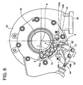
- An actuator drives an actuator rod 40(see FIG.8 ) to rotate a ring assembly 10 (annular link mechanism, see FIG.1 ) around the rotation axis 8 of the turbine rotor shaft 33.
- the nozzle vanes are rotated by the rotation of the ring assembly 10 to be changed in their wing angle.
- the exhaust gas from an internal combustion engine enters into the scroll passage 38 and flows in the nozzle vanes 1 circling along the spiral of the scroll passage 38.
- the exhaust gas flows through the wing space between the nozzle vanes, enters into the turbine wheel 34 from the outer circumference thereof, flows in the radial inward direction expanding while executing work to the turbine wheel 34, and exits from the exhaust outlet 49 in the longitudinal direction.
- the means of assembling and adjusting the adjustable nozzle mechanism of the variable capacity turbine is improved as described hereinafter.
- reference number 10 is a ring assembly comprising a link plate 3 of disk like shape and lever plates 2 connected with the link plate 3 by means of link parts 10a.
- the same number of the link parts 10a and lever plates 2 as that of the nozzle vanes 1 are provided, each corresponding to each nozzle vane, spaced at regular circular intervals as shown in FIG.3 .
- Reference number 03 is a connection part of the link plate 3. As shown in FIG.8 , a drive lever 41 which is connected to an actuator rod 40 is connected to the connection part 03 by means of a connection pin 9 fitted to the connection part.
- Reference number 4 is an annular shape nozzle mount fixed to the turbine casing 30, 5 is a disk like nozzle plate. A number of nozzle supports 7 are provided along the circumferential direction to fix the nozzle plate 5 to the nozzle mount 4.
- the nozzle vanes 1 are disposed inside the nozzle support between the nozzle mount 4 and nozzle plate 5.
- Nozzle pins 6 fixed to the nozzle vanes (or integral with the nozzle vanes) are supported free of rotation by the nozzle mount 4.
- Each nozzle pin 6 fixed to each nozzle vane is fixed to the lever plate 2 at the lower end part thereof by staking at its end part as indicated by reference number 2a.
- the drive lever 41 is supported by the turbine casing 30 at its center part by the support shaft 42.
- An end part of the drive lever 41 is connected to the connection part 03 of the link plate 3 by means of the connection pin 9, and the other end is connected to the actuator rod 40 extending from an actuator not shown in the drawing.
- the drive lever 41 swings around the support shaft 42 according to the reciprocating motion of the actuator rod 40, and the link plate 3 is driven to rotate around the rotation axis 8 of the turbine by means of the connection part 03 of the link plate 3 to which the drive lever 41 is connected.
- the reciprocating movement of the actuator rod 40 and the swing movement of the nozzle vanes are the same as those of the ordinary variable capacity turbines.
- the method of assembling and adjusting the adjustable nozzle mechanism 100 of the variable capacity turbine equipped with the adjustable nozzle mechanism 100 of the construction described above will be explained.
- the plurality of the nozzle vanes 1 are disposed to contact each other in a perfectly closed state and encircled with a belt 11 to be temporarily bound. By this, a number of the nozzle vanes 1 are all set to the perfectly closed state.
- the member for binding the nozzle vanes 1 is not limited to be the belt 11, a string, a rubber member, and the like may be usable as far as it is easy to bind and release the vanes.
- the ring assembly 10 is prepared beforehand by fitting an end side of each of the link parts 10a free for rotation to the link plate 3 and further fitting the upper end part of each of the lever plates 2 free for rotation to the other end of each of the link parts 10a.
- Each of the nozzle vanes 1 is fitted between the nozzle mount 4 and nozzle plate 5, the nozzle mount 4 and nozzle plate 5 are positioned and fixed to the nozzle supports 7 by the conventional method.
- the position of the ring assembly 10 corresponding to the perfect closing position of the nozzle vanes is determined by one of the following two methods.
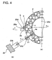
- FIG.4 and FIG.5 represent the first method.
- a radial matching hole 4a is drilled in the nozzle mount 4 at the position apart from the center of the connection pin 9 which is to connect the drive lever 41 (see FIG.8 ) by an angle A as shown in FIG.3 .
- the position of the ring assembly 10 relative to the matching hole 4a of the nozzle mount 4 is determined by use of a jig (A) 20 of which the central angle between the contact face 20d of the contact part 20a and the center of the angle locating part 20b is pre-determined and a rod like jig (B) 21, through inserting the end part of the jig (B) 21 inserted in the angle locating part 20b of the jig (A) into the matching hole 4a and allowing the side face 3a of the connection part 03 of the link plate 3 to contact with the contact face 20d of the jig(A) 20.
- nozzle pins 6 which is integral with the nozzle vanes and supported free for rotation in the nozzle mount 4 are fixed to the lever plates 2 by staking in the holes at the lower end part of the lever plates 2 which constitute the connection parts of the ring assembly 10.
- a staking port ion is indicated in FIG.1 by reference number 2a.
- FIG.6 the second method is represented in FIG.6 , in which a radial matching hole 4a is drilled in the nozzle mount 4 at the position apart from the center of the connection pin 9 by an angle A the same as the case of the first method.
- the position of the ring assembly 10 relative to the matching hole 4a of the nozzle mount 4 is determined by use of a jig(C) 22 of which an arm 22a is provided with a hole 22c at an end part thereof into which said jig (B) 21 inserted and with a groove 22b which is formed so that the head part of the link pin 9 of the link plate 3 (or the connection part 03 shown in FIG.3 ) can be inserted and the center angle between the hole 22c and the groove 22b is pre-determined to be A, by inserting the end part of the jig (B) 21 inserted into the hole 22c of the jig(C) 22 into the matching hole 4a of the nozzle mount 4 and fitting the groove 22b to the head part of the connection pin 9 (or the connection part 03 shown in FIG.3 ).
- the perfect closing positions of all the nozzle vanes 1 are thus determined in the ring assembly 10.
- the adjustment of the perfect closing position after the adjustable nozzle mechanism 100 adjusted as described above is installed into a variable capacity turbine can be done as follows: the nozzle vanes 1 bound with the belt 11 (binding member) to keep the temporarily fixed state are released from the bound state, and the position of the set of the nozzle vanes is adjusted by the adjusting screw 44a and the locking nut 44b of a shutdown side stopper 44 which is provided for limiting the shift of the drive lever 41 connecting the ring assembly 10 to the actuator rod 40 as shown in FIG.8 . This adjustment can be done in the state where the variable capacity turbine is assembled.
- the stopper mechanism provided for setting perfect closing position in the prior art nozzle assembly is unnecessary and omitted, variations in dimensions of the nozzle vanes 1 and the ring assembly can be absorbed, assembling of the nozzle assembly including nozzle vanes 1 is simplified, and the setting of various specifications of the adjustable nozzle mechanism is possible with the same nozzle assembly.
- Reference number 43 is a maximum stopper, wherein the adjustment of the full open position can be done by an adjusting screw 43a and a lock nut 43b of the maximum stopper 43 in the state the adjustable capacity turbine is assembled.
- a plurality of the nozzle vanes 1 are bound temporarily by encircling them with a belt 11 (binding member) capable of easy binding/releasing to fix them in a perfect closed state with the vanes contacting to each other, then the positioning of the nozzle vane 1 side (nozzle assembly) relative to the ring assembly (annular link mechanism) 10 side is done by the first or second method using the jigs (A) and (B), or (B) and (C), and each of the nozzle pins which are fixed to the nozzle vanes to be integral with the vanes is fixed to each lever plate 2 constituting the connection part of the ring assembly by staking, so the adjustment of perfect closing position of the vanes in the nozzle assembling process is unnecessary and the adjustment of the perfect closing position can be done freely by the minimum stopper 44 in the state when the variable capacity turbine is assembled.
- the adjustable nozzle mechanism 100 is set by this simple method in which a plurality of the nozzle vanes 1 are bound by an encircling band 11 (binding member), the relative position of the nozzle assembly to the ring assembly is determined by use of jigs, and each nozzle vane is fixed to each lever plate, and which eliminates the necessity of adjustment of the perfect closing position in nozzle assembling process, the assembling and adjustment procedure is extremely simplified resulting in reduction of man-hours for assembling and adjustment, accordingly manufacturing cost is reduced compared with the prior art according to Japanese Patent No.3085210 in which the adjustment of the perfect closing position is done by use of a plurality of long slots in the link plate, stopper pins and jigs in the nozzle assembling process.
- a plurality of the nozzle vanes 1 are bound by encircling them with the belt 11 to determine the perfect closing position, each nozzle vane is fixed to the lever plate 2, and the adjustment of the perfect closing position is done as a whole by the minimum stopper 44 in the assembled state of the variable capacity turbine, so errors in dimensions of the nozzle assembly including nozzle vanes 1 and the ring assembly in their assembled states can be absorbed. Therefore, the perfect closing position of each nozzle vane is not determined uniquely according to the accuracy of the constituent parts and the setting of the perfect closing position is possible with good accuracy without being influenced by the accuracy in dimensions of the nozzle assembly and ring assembly, contrary to the case of Japanese Patent No.
- variable capacity turbine has the same function as the exhaust brake of a truck and so forth by adjusting the perfect closing position by the minimum stopper 44.
- adjustable nozzle mechanism assembly 100 can be transferred and assembled into the turbine in the state in which a plurality of the nozzle vanes 1 are encircled and bound with the belt 11 and fixed to the supporting parts of the nozzle mount 4, damage to the constituent parts of the nozzle assembly due to vibration or impact is prevented.
- a plurality of nozzle vanes are encircled with a binding member capable of binding/releasing to temporarily fix the vanes in a state where the vanes are perfectly closed with the vanes contacting to each other; then the positioning of the nozzle vane side, i.e. the nozzle assembly side relative to the annular link mechanism side, is performed by use of jigs in the temporarily fixed state; and the driving part of each nozzle vane is fixed to each connection part of the annular link mechanism; so the adjustment of the perfect closing position is unnecessary in the nozzle assembling process, and the adjustment of perfect closing position is possible in the assembled state of the variable capacity turbine.
- the adjustable nozzle mechanism is set by this simple method in which a plurality of the nozzle vanes are bound by an encircling binding member, the relative position of the nozzle assembly to the annular link mechanism is determined by use of jigs, and each nozzle vane is fixed to each lever plate, and which eliminates the necessity of adjustment of perfect closing position in nozzle assembling process, the assembling and adjustment procedure is extremely simplified resulting in reduction of man-hours for assembling and adjustment, accordingly manufacturing cost reduces.
- each nozzle vane is fixed to the lever plate 2, and the adjustment of the perfect closing position is done as a whole by a minimum stopper in the assembled state of the variable capacity turbine, errors in dimensions of the nozzle assembly including nozzle vanes and the ring assembly including the link plate and link parts in their assembled states can be absorbed. Therefore, the setting of the adjustable nozzle mechanism is possible with good accuracy without being influenced by the accuracy in dimensions of the nozzle assembly and ring assembly, and also the adjustable nozzle mechanism is adaptable to various specifications.
- variable capacity turbine has the same function as the exhaust brake of truck and so forth by adjusting the perfect closing position by the minimum stopper.
- the adjustment of the full open position of the nozzle vanes is possible by the maximum stopper in the assembled state of the variable capacity turbine.
- the adjustable nozzle mechanism assembly can be transferred and installed into the turbine in the state in which a plurality of the nozzle vanes are temporarily encircled and bound with the binding member and fixed to the supporting parts of the nozzle mount 4, damage to the constituent parts of the nozzle assembly due to vibration or impact is prevented.
Abstract
Description
- The present invention relates to a method and device for assembling and adjusting the adjustable nozzle mechanism of a radial flow turbine used as the supercharger of an internal combustion engine (exhaust turbocharger) and so forth, the turbine being configured so that the actuating gas flows from the spiral scroll formed in the turbine casing to the turbine rotor in the radial direction via a plurality of nozzle vanes of variable wing angle to rotate the turbine rotor.
- In order to make a good match of the exhaust gas flow rate of the engine with that with which the supercharger operates in the optimum operation condition, superchargers equipped with variable capacity turbines capable of changing the exhaust gas flow rate in accordance with the operating condition of the engines, have been in wide spread use in recent years in internal combustion engines with superchargers.
- A supercharger with such a variable capacity turbine is equipped with an adjustable nozzle mechanism in order to change the turbine capacity. The adjustable nozzle mechanism can change the wing angle of the nozzle vanes through rotating the nozzle vanes by means of an annular link mechanism (ring assembly) which is driven to rotate around the rotation center of the turbine rotor by an actuator by way of an actuator rod.
- For a method to achieve assembling and adjustment of such an adjustablenozzle mechanism, an invention of
Japanese Patent No.3,085,210 - Also,
DE 4 309 636 - In the concerned invention, a jig should be placed in the inner radius of the nozzle vane to perform the setup for perfect closing of the nozzle vane and the ring assembly to be driven for rotations around the turbine rotor shaft. The jig therein can be put in contact with the rear edge of the nozzle vane, wherein the stopper pin is mounted after the nozzle vane and the lever plates are welded together upon putting the nozzle vane in contact with the jig in the state that the stopper pin, that is to be fitted into the long slots located at multiple positionsalongthecircumferentialdirectionofthelinkplate, is made non-functional or non-existing, and upon fitting the matching pin into the phase matching hole to finalize the entire ring assembly in the perfect closing phase.
- However, according to the invention of
Japanese Patent No.3,085,210 - According to the conventional art, the setup for perfect closing of the adjustable nozzle mechanism is done by fitting each stopper pin into each long slot provided on the link plate along the circumferential direction and matching the contact angle with the lever plate by contacting the tail end of the nozzle bane with the jig, so variations in setup for perfect closing tend to occur resulting in setup error. Moreover, as the perfect closing position of the adjustable nozzle mechanism is influenced by the accuracy of such constituent parts as described above, the adjustment is difficult after assembling turbine.
- In consideration of the problems with the conventional art mentioned above, the object of this invention is to provide a method and device for assembling and adjusting a variable capacity turbine, which simplifies the assembling and adjustment process of an adjustable nozzle mechanism to reduce man-hours and costs for assembling and adjustment, is capable of setting up the positions of the nozzle vanes of an adjustable nozzle mechanism with good accuracy without influenced by the accuracy in dimension of the constituent parts such as nozzle vanes, annular link assemblies (ring assembly), etc., and is capable of adjusting the adjustable nozzle mechanism whenever necessary even after they are assembled.
- In order to solve the concerned problems, the invention proposes a method according to Claim 1 of and a device according to
claim 8 for assembling and adjusting a variable capacity turbine having a plurality of nozzle vanes disposed along the circumferential direction of a turbine rotor in the inner radius side of a spiral scroll formed in a turbine casing and supported for rotation on a supporting part of a nozzle mount. - Preferred embodiments are defined in the dependent claims.
- According to the present invention the assembling and adjustment procedure is extremely simplified compared with the prior art disclosed on
Japanese Patent No.3085210 -
-
FIG.1 is a longitudinal partial sectional view showing the adjustable nozzle mechanism of the supercharger with a variable capacity turbine. -
FIG.2 is a sectional view along line A-A ofFIG.1 . -
FIG.3 is a view in the direction of arrow B ofFIG.1 . -
FIG.4(A) and FIG.4(B) represent the first example of the method of assembling and adjusting the adjustable nozzle mechanism;FIG.4 (A) is a view in the direction of arrow B ofFIG.1 , andFIG.4(B) is a view in the direction of arrow D ofFIG.4 (A) . -
FIG.5 is a view in the direction C ofFIG.4 (A) . -
FIG.6 represents the second example of the method of assembling and adjusting the adjustable nozzle mechanism and shows a view in the direction of arrow B ofFIG.1 . -
FIG.7 is a longitudinal sectional view of the supercharger with a variable capacity turbine to which the present invention is applied. -
FIG.8 is a view in the direction of arrows E-E ofFIG.7 . - A preferred embodiment of the present invention will now be detailed with reference to the accompanying drawings. It is intended, however, that unless particularly specified, dimensions, materials, relative positions and so forth of the constituent parts in the embodiments shall be interpreted as illustrative only not to limit the scope of the present invention.
- In
FIG.7 showing the structure of the supercharger with variable capacity turbine to which the present invention is applied,reference number 30 is a turbine casing, 38 is a scroll passage formed in spiral around the circumference section in theturbine casing scroll passage turbine wheel 34.Reference number 31 is a compressor casing, 36 is a bearing housing which connects thecompressor casing 31 with theturbine casing 30.Reference number 34 is a turbine wheel, 35 is a compressor wheel, 33 is a turbine rotor shaft connecting thecompressor wheel 35 to theturbine wheel bearing housing 36 for supporting theturbine rotor shaft 33. - Reference number 1 are nozzle vanes which are positioned around the circumferential inlet of the
turbine wheel 34 in the inner side of thescroll passage 38 spaced at regular intervals. The nozzle pins (seeFIG.1 ) formed integral with the nozzle vanes are supported free for rotation in anozzle mount 4 fixed to theturbine casing 30, and thus the wing angle of the nozzle vanes is able to be changed. -
Reference number 100 is an adjustable nozzle mechanism. An actuator drives an actuator rod 40(seeFIG.8 ) to rotate a ring assembly 10 (annular link mechanism, seeFIG.1 ) around therotation axis 8 of theturbine rotor shaft 33. The nozzle vanes are rotated by the rotation of thering assembly 10 to be changed in their wing angle. - With this construction of the supercharger with variable capacity turbine, the exhaust gas from an internal combustion engine (not shown) enters into the
scroll passage 38 and flows in the nozzle vanes 1 circling along the spiral of thescroll passage 38. The exhaust gas flows through the wing space between the nozzle vanes, enters into theturbine wheel 34 from the outer circumference thereof, flows in the radial inward direction expanding while executing work to theturbine wheel 34, and exits from theexhaust outlet 49 in the longitudinal direction. - According to the present invention, the means of assembling and adjusting the adjustable nozzle mechanism of the variable capacity turbine is improved as described hereinafter.
- In
FIG.1~3 andFIG.8 ,reference number 10 is a ring assembly comprising alink plate 3 of disk like shape andlever plates 2 connected with thelink plate 3 by means oflink parts 10a. The same number of thelink parts 10a andlever plates 2 as that of the nozzle vanes 1 are provided, each corresponding to each nozzle vane, spaced at regular circular intervals as shown inFIG.3 . -
Reference number 03 is a connection part of thelink plate 3. As shown inFIG.8 , adrive lever 41 which is connected to anactuator rod 40 is connected to theconnection part 03 by means of aconnection pin 9 fitted to the connection part.
Reference number 4 is an annular shape nozzle mount fixed to theturbine casing nozzle supports 7 are provided along the circumferential direction to fix thenozzle plate 5 to thenozzle mount 4. - The nozzle vanes 1 are disposed inside the nozzle support between the
nozzle mount 4 andnozzle plate 5.Nozzle pins 6 fixed to the nozzle vanes (or integral with the nozzle vanes) are supported free of rotation by thenozzle mount 4. Eachnozzle pin 6 fixed to each nozzle vane is fixed to thelever plate 2 at the lower end part thereof by staking at its end part as indicated byreference number 2a. - In
FIG.8 , thedrive lever 41 is supported by theturbine casing 30 at its center part by thesupport shaft 42. An end part of thedrive lever 41 is connected to theconnection part 03 of thelink plate 3 by means of theconnection pin 9, and the other end is connected to theactuator rod 40 extending from an actuator not shown in the drawing. - The drive lever 41 swings around the
support shaft 42 according to the reciprocating motion of theactuator rod 40, and thelink plate 3 is driven to rotate around therotation axis 8 of the turbine by means of theconnection part 03 of thelink plate 3 to which thedrive lever 41 is connected. - As the
lever plate 2 swings according to the rotation of thelink plate 3 by means of thelink parts 10a, thenozzle pins 6 fixed by staking to thelever plates 2 at the lower end parts thereof rotate, and the nozzle vanes 1 integral with thenozzle pins 6 rotate, as can be understood fromFIG.3 andFIG.8 . - The reciprocating movement of the
actuator rod 40 and the swing movement of the nozzle vanes are the same as those of the ordinary variable capacity turbines.
Next, the method of assembling and adjusting theadjustable nozzle mechanism 100 of the variable capacity turbine equipped with theadjustable nozzle mechanism 100 of the construction described above will be explained. - At first, the plurality of the nozzle vanes 1 are disposed to contact each other in a perfectly closed state and encircled with a
belt 11 to be temporarily bound. By this, a number of the nozzle vanes 1 are all set to the perfectly closed state. The member for binding the nozzle vanes 1 is not limited to be thebelt 11, a string, a rubber member, and the like may be usable as far as it is easy to bind and release the vanes. - The
ring assembly 10 is prepared beforehand by fitting an end side of each of thelink parts 10a free for rotation to thelink plate 3 and further fitting the upper end part of each of thelever plates 2 free for rotation to the other end of each of thelink parts 10a. - Each of the nozzle vanes 1 is fitted between the
nozzle mount 4 andnozzle plate 5, thenozzle mount 4 andnozzle plate 5 are positioned and fixed to the nozzle supports 7 by the conventional method. - Then, the position of the
ring assembly 10 corresponding to the perfect closing position of the nozzle vanes is determined by one of the following two methods. -
FIG.4 andFIG.5 represent the first method. Aradial matching hole 4a is drilled in thenozzle mount 4 at the position apart from the center of theconnection pin 9 which is to connect the drive lever 41 (seeFIG.8 ) by an angle A as shown inFIG.3 . - The position of the
ring assembly 10 relative to thematching hole 4a of thenozzle mount 4 is determined by use of a jig (A) 20 of which the central angle between thecontact face 20d of thecontact part 20a and the center of theangle locating part 20b is pre-determined and a rod like jig (B) 21, through inserting the end part of the jig (B) 21 inserted in theangle locating part 20b of the jig (A) into thematching hole 4a and allowing theside face 3a of theconnection part 03 of thelink plate 3 to contact with thecontact face 20d of the jig(A) 20. - In this condition, the nozzle pins 6 which is integral with the nozzle vanes and supported free for rotation in the
nozzle mount 4 are fixed to thelever plates 2 by staking in the holes at the lower end part of thelever plates 2 which constitute the connection parts of thering assembly 10. A staking port ion is indicated inFIG.1 byreference number 2a. - Next, the second method is represented in
FIG.6 , in which aradial matching hole 4a is drilled in thenozzle mount 4 at the position apart from the center of theconnection pin 9 by an angle A the same as the case of the first method. - The position of the
ring assembly 10 relative to thematching hole 4a of thenozzle mount 4 is determined by use of a jig(C) 22 of which anarm 22a is provided with ahole 22c at an end part thereof into which said jig (B) 21 inserted and with agroove 22b which is formed so that the head part of thelink pin 9 of the link plate 3 (or theconnection part 03 shown inFIG.3 ) can be inserted and the center angle between thehole 22c and thegroove 22b is pre-determined to be A, by inserting the end part of the jig (B) 21 inserted into thehole 22c of the jig(C) 22 into thematching hole 4a of thenozzle mount 4 and fitting thegroove 22b to the head part of the connection pin 9 (or theconnection part 03 shown inFIG.3 ). - With this condition, the nozzle pins 9 integral with the nozzle vanes 1 are fixed to the lever plate by staking in the hole at the lower end part of the
lever plate 2 of the ring assembly 10 (2a inFIG.1 indicates a staking portion). - The perfect closing positions of all the nozzle vanes 1 are thus determined in the
ring assembly 10.
The adjustment of the perfect closing position after theadjustable nozzle mechanism 100 adjusted as described above is installed into a variable capacity turbine, can be done as follows: the nozzle vanes 1 bound with the belt 11 (binding member) to keep the temporarily fixed state are released from the bound state, and the position of the set of the nozzle vanes is adjusted by the adjustingscrew 44a and the lockingnut 44b of ashutdown side stopper 44 which is provided for limiting the shift of thedrive lever 41 connecting thering assembly 10 to theactuator rod 40 as shown inFIG.8 . This adjustment can be done in the state where the variable capacity turbine is assembled. - Therefore, the stopper mechanism provided for setting perfect closing position in the prior art nozzle assembly is unnecessary and omitted, variations in dimensions of the nozzle vanes 1 and the ring assembly can be absorbed, assembling of the nozzle assembly including nozzle vanes 1 is simplified, and the setting of various specifications of the adjustable nozzle mechanism is possible with the same nozzle assembly.
-
Reference number 43 is a maximum stopper, wherein the adjustment of the full open position can be done by an adjustingscrew 43a and alock nut 43b of themaximum stopper 43 in the state the adjustable capacity turbine is assembled. - According to the embodiment, a plurality of the nozzle vanes 1 are bound temporarily by encircling them with a belt 11 (binding member) capable of easy binding/releasing to fix them in a perfect closed state with the vanes contacting to each other, then the positioning of the nozzle vane 1 side (nozzle assembly) relative to the ring assembly (annular link mechanism) 10 side is done by the first or second method using the jigs (A) and (B), or (B) and (C), and each of the nozzle pins which are fixed to the nozzle vanes to be integral with the vanes is fixed to each
lever plate 2 constituting the connection part of the ring assembly by staking, so the adjustment of perfect closing position of the vanes in the nozzle assembling process is unnecessary and the adjustment of the perfect closing position can be done freely by theminimum stopper 44 in the state when the variable capacity turbine is assembled. - As the
adjustable nozzle mechanism 100 is set by this simple method in which a plurality of the nozzle vanes 1 are bound by an encircling band 11 (binding member), the relative position of the nozzle assembly to the ring assembly is determined by use of jigs, and each nozzle vane is fixed to each lever plate, and which eliminates the necessity of adjustment of the perfect closing position in nozzle assembling process, the assembling and adjustment procedure is extremely simplified resulting in reduction of man-hours for assembling and adjustment, accordingly manufacturing cost is reduced compared with the prior art according toJapanese Patent No.3085210 - According to the embodiment, a plurality of the nozzle vanes 1 are bound by encircling them with the
belt 11 to determine the perfect closing position, each nozzle vane is fixed to thelever plate 2, and the adjustment of the perfect closing position is done as a whole by theminimum stopper 44 in the assembled state of the variable capacity turbine, so errors in dimensions of the nozzle assembly including nozzle vanes 1 and the ring assembly in their assembled states can be absorbed. Therefore, the perfect closing position of each nozzle vane is not determined uniquely according to the accuracy of the constituent parts and the setting of the perfect closing position is possible with good accuracy without being influenced by the accuracy in dimensions of the nozzle assembly and ring assembly, contrary to the case ofJapanese Patent No. 3085210 adjustable nozzle mechanism 100 for various specifications is possible together with the setting with good accuracy. - It is also possible that the variable capacity turbine has the same function as the exhaust brake of a truck and so forth by adjusting the perfect closing position by the
minimum stopper 44. - As the adjustable
nozzle mechanism assembly 100 can be transferred and assembled into the turbine in the state in which a plurality of the nozzle vanes 1 are encircled and bound with thebelt 11 and fixed to the supporting parts of thenozzle mount 4, damage to the constituent parts of the nozzle assembly due to vibration or impact is prevented. - As described hitherto, according to the present invention, a plurality of nozzle vanes are encircled with a binding member capable of binding/releasing to temporarily fix the vanes in a state where the vanes are perfectly closed with the vanes contacting to each other; then the positioning of the nozzle vane side, i.e. the nozzle assembly side relative to the annular link mechanism side, is performed by use of jigs in the temporarily fixed state; and the driving part of each nozzle vane is fixed to each connection part of the annular link mechanism; so the adjustment of the perfect closing position is unnecessary in the nozzle assembling process, and the adjustment of perfect closing position is possible in the assembled state of the variable capacity turbine.
- As the adjustable nozzle mechanism is set by this simple method in which a plurality of the nozzle vanes are bound by an encircling binding member, the relative position of the nozzle assembly to the annular link mechanism is determined by use of jigs, and each nozzle vane is fixed to each lever plate, and which eliminates the necessity of adjustment of perfect closing position in nozzle assembling process, the assembling and adjustment procedure is extremely simplified resulting in reduction of man-hours for assembling and adjustment, accordingly manufacturing cost reduces.
- As a plurality of nozzle vanes are bound by encircling them with a binding member to determine the perfect closing position, each nozzle vane is fixed to the
lever plate 2, and the adjustment of the perfect closing position is done as a whole by a minimum stopper in the assembled state of the variable capacity turbine, errors in dimensions of the nozzle assembly including nozzle vanes and the ring assembly including the link plate and link parts in their assembled states can be absorbed. Therefore, the setting of the adjustable nozzle mechanism is possible with good accuracy without being influenced by the accuracy in dimensions of the nozzle assembly and ring assembly, and also the adjustable nozzle mechanism is adaptable to various specifications. - It is also possible that the variable capacity turbine has the same function as the exhaust brake of truck and so forth by adjusting the perfect closing position by the minimum stopper. The adjustment of the full open position of the nozzle vanes is possible by the maximum stopper in the assembled state of the variable capacity turbine.
- As the adjustable nozzle mechanism assembly can be transferred and installed into the turbine in the state in which a plurality of the nozzle vanes are temporarily encircled and bound with the binding member and fixed to the supporting parts of the
nozzle mount 4, damage to the constituent parts of the nozzle assembly due to vibration or impact is prevented.
Claims (10)
- A method of assembling and adjusting a variable capacity turbine having
a plurality of nozzle vanes (1) disposed along the circumferential direction of a turbine rotor in the inner radius side of a spiral scroll (38) formed in a turbine casting (30) and supported for rotation on a supporting part of a nozzle mount (4),
wherein the turbine rotor is supported in the turbine casing (3) for rotation around a rotation axis (8); and
wherein an annular link mechanism (10) is mounted for rotation with respect to the rotation axis (8) and is provided with connection parts (2,10a) each of which is connected with a driving part (6) of each of said nozzle vanes (1) and with an output end of an actuator mechanism (40, 41) ;
said method being characterized by the steps of:temporarily encircling and binding said plurality of nozzle vanes (1) in a state where the vanes (1) are perfectly closed and contact each other with a binding member (11) that is capable of binding/releasing said vanes (1), and thenfixing the driving part (6) of each nozzle vane (1) to the respective connection part (2,10a) of the annular link mechanism (10) with the vanes (1) in the temporarily bound state. - The method according to claim 1, wherein nozzle pins (6) which constitute said driving part and which are fixed to or are integral with one of the nozzle vanes (1) and are supported in said nozzle mount (4) for rotation are fixed to lever plates (2) of the connection parts of the annular link mechanism (10) by means of staking or the like in the temporarily bound state with the vanes (1) perfectly closed.
- The method according to claim 1 or 2, wherein the constituent parts are transferred or installed into the turbine in the state of a nozzle assembly temporarily fixed to the supporting part of said nozzle mount (4) by encircling and binding the vanes (1) with the binding member (11) in the state where the vanes (1) are perfectly closed and contact each other.
- The method according to claim 2, wherein
a nozzle vane side mating part (4a) is provided in the nozzle mount (4),
a link side mating part is provided in the annular link mechanism (10),
a jig (20,21;21,22) is prepared to which is formed at an end side a portion for determining the nozzle vane side position and to which is formed at the other end side a portion for determining the annular link mechanism side position, said portion of said jig (20,21;21,22) for determining the nozzle vane side position is mated with said nozzle vane side mating part (4a) of said nozzle mount (4) and said link side mating part is mated with said portion for determining the annular link mechanism side position with each nozzle vane (1) temporarily fixed in the perfect closing position, and
the perfect closing position of the nozzle vane side and the annular link mechanism side is set up by fixing said nozzle pins (6) to said lever plates (2) by staking or the like. - The method according to claim 4, wherein
said nozzle mount (4) is provided with a mating hole (4a) as said nozzle vane side mating part,
said jig (20,21) is provided with a pin-like protrusion as said portion for determining the nozzle vane side position and with a contact face (20d) capable of contacting with a face of a link plate (3) of said annular link mechanism (10) as said portion for determining the annular link mechanism side position. - The method according to claim 4, wherein
said nozzle mount is provided with a mating hole (4a) as said nozzle vane side mating part,
said jig (21,22) is provided with a pin-like protrusion as said portion for determining the nozzle vane side position and with a groove (22b) capable of meshing with a connection pin (9) of a link plate (3) of said annular link mechanism (10) as said portion for determining the annular link mechanism side position. - The method according to any one of claims 1 to 6,
wherein said binding member (11) used for temporarily encircling and binding said plurality of nozzle vanes (1) in the state where the vanes (1) are perfectly closed and contact each other is a belt, a string or a rubber member. - A device for assembling and adjusting a variable capacity turbine having
a plurality of nozzle vanes (1) disposed along the circumferential direction of a turbine rotor in the inner radius side of a spiral scroll (38) formed in a turbine casing (30) and supported for rotation on a supporting part of a nozzle mount (4),
wherein the turbine rotor is supported in the turbine casing (3) for rotation around a rotation axis (8); and
wherein an annular link mechanism (10) is mounted for rotation with respect to the rotation axis (8) and is provided with connection parts (2,10a) each of which is connected with a driving part (6) of each of said nozzle vanes (1) and with an output end of an actuator mechanism (40,41);
said device comprising:a binding member (11) which is capable of binding/releasing by encircling said plurality of nozzle vanes (1) to fix them in a perfect closing position with the vanes (1) contacting each other; anda minimum stopper (44) for limiting the shift of a linkage (41) connecting said actuator mechanism (40,41) and said annular link mechanism (10) toward a perfect closing side. - The device according to claim 8, further comprising a maximum stopper (43) for limiting the shift of the linkage (41) toward a full open side.
- The device according to claim 8 or 9, wherein said binding member (11) is a belt, a string or a rubber member.
Applications Claiming Priority (2)
| Application Number | Priority Date | Filing Date | Title |
|---|---|---|---|
| JP2001057834A JP3482196B2 (en) | 2001-03-02 | 2001-03-02 | Method and apparatus for assembling and adjusting variable capacity turbine |
| JP2001057834 | 2001-03-02 |
Publications (3)
| Publication Number | Publication Date |
|---|---|
| EP1236867A2 EP1236867A2 (en) | 2002-09-04 |
| EP1236867A3 EP1236867A3 (en) | 2005-09-21 |
| EP1236867B1 true EP1236867B1 (en) | 2008-12-03 |
Family
ID=18917650
Family Applications (1)
| Application Number | Title | Priority Date | Filing Date |
|---|---|---|---|
| EP02004744A Expired - Lifetime EP1236867B1 (en) | 2001-03-02 | 2002-03-01 | Method and device for assembling and adjusting pivotable nozzle vanes of variable capacity turbine |
Country Status (7)
| Country | Link |
|---|---|
| US (1) | US6669442B2 (en) |
| EP (1) | EP1236867B1 (en) |
| JP (1) | JP3482196B2 (en) |
| KR (1) | KR100504052B1 (en) |
| AT (1) | ATE416301T1 (en) |
| BR (1) | BR0200633B1 (en) |
| DE (1) | DE60230083D1 (en) |
Families Citing this family (34)
| Publication number | Priority date | Publication date | Assignee | Title |
|---|---|---|---|---|
| JP3482196B2 (en) * | 2001-03-02 | 2003-12-22 | 三菱重工業株式会社 | Method and apparatus for assembling and adjusting variable capacity turbine |
| JP4008404B2 (en) | 2002-10-18 | 2007-11-14 | 三菱重工業株式会社 | Variable displacement exhaust turbocharger |
| US7150151B2 (en) * | 2002-11-19 | 2006-12-19 | Cummins Inc. | Method of controlling the exhaust gas temperature for after-treatment systems on a diesel engine using a variable geometry turbine |
| US7207176B2 (en) * | 2002-11-19 | 2007-04-24 | Cummins Inc. | Method of controlling the exhaust gas temperature for after-treatment systems on a diesel engine using a variable geometry turbine |
| EP1635040A1 (en) * | 2004-09-08 | 2006-03-15 | BorgWarner Inc. | Method of assembling a variable inlet guide vane assembly and jig therefor |
| US20060185464A1 (en) * | 2005-02-22 | 2006-08-24 | Borgwarner Inc. | Rotary actuator |
| JP4545068B2 (en) * | 2005-08-25 | 2010-09-15 | 三菱重工業株式会社 | Variable displacement exhaust turbocharger and variable nozzle mechanism component manufacturing method |
| FR2890136B1 (en) * | 2005-08-30 | 2007-11-09 | Snecma | ROD WITH AN EVOLVING LENGTH IN OPERATION |
| KR100802762B1 (en) * | 2006-11-01 | 2008-02-12 | 현대자동차주식회사 | System and method controlling minimum flow rate of variable geometry turbocharger |
| JP4885118B2 (en) * | 2007-12-21 | 2012-02-29 | 三菱重工業株式会社 | Variable displacement exhaust turbocharger with variable nozzle mechanism |
| WO2009102546A1 (en) * | 2008-02-12 | 2009-08-20 | Honeywell International Inc. | Process for calibrating a variable-nozzle assembly of a turbochanger and a variable-nozzle assembly facilitating such process |
| US8122716B2 (en) | 2008-06-04 | 2012-02-28 | Honeywell International Inc. | VNT flow calibration adjustment |
| US8245518B2 (en) * | 2008-11-28 | 2012-08-21 | Pratt & Whitney Canada Corp. | Mid turbine frame system for gas turbine engine |
| US8061969B2 (en) * | 2008-11-28 | 2011-11-22 | Pratt & Whitney Canada Corp. | Mid turbine frame system for gas turbine engine |
| US20100132377A1 (en) * | 2008-11-28 | 2010-06-03 | Pratt & Whitney Canada Corp. | Fabricated itd-strut and vane ring for gas turbine engine |
| US8347500B2 (en) * | 2008-11-28 | 2013-01-08 | Pratt & Whitney Canada Corp. | Method of assembly and disassembly of a gas turbine mid turbine frame |
| US8099962B2 (en) * | 2008-11-28 | 2012-01-24 | Pratt & Whitney Canada Corp. | Mid turbine frame system and radial locator for radially centering a bearing for gas turbine engine |
| US20100132371A1 (en) * | 2008-11-28 | 2010-06-03 | Pratt & Whitney Canada Corp. | Mid turbine frame system for gas turbine engine |
| US8347635B2 (en) * | 2008-11-28 | 2013-01-08 | Pratt & Whitey Canada Corp. | Locking apparatus for a radial locator for gas turbine engine mid turbine frame |
| US8091371B2 (en) * | 2008-11-28 | 2012-01-10 | Pratt & Whitney Canada Corp. | Mid turbine frame for gas turbine engine |
| US8231326B2 (en) * | 2009-03-31 | 2012-07-31 | Nuovo Pignone S.P.A. | Nozzle adjusting mechanism and method |
| JP5353635B2 (en) * | 2009-10-27 | 2013-11-27 | 株式会社Ihi | Vane aligning apparatus and vane aligning method |
| JP5407814B2 (en) * | 2009-12-01 | 2014-02-05 | 株式会社Ihi | Vane aligner |
| WO2011068267A1 (en) * | 2009-12-04 | 2011-06-09 | (주)계양정밀 | Variable nozzle device of turbocharger |
| CN102648341B (en) * | 2009-12-07 | 2015-07-22 | 沃尔沃拉斯特瓦格纳公司 | Vane travel adjustement screw |
| US9388708B2 (en) * | 2010-05-19 | 2016-07-12 | Borgwarner Inc. | Turbocharger |
| DE112012002909T5 (en) * | 2011-08-08 | 2014-03-27 | Borgwarner Inc. | turbocharger |
| JP5409741B2 (en) | 2011-09-28 | 2014-02-05 | 三菱重工業株式会社 | Opening restriction structure of variable nozzle mechanism and variable capacity turbocharger |
| US9429033B2 (en) * | 2013-11-08 | 2016-08-30 | Honeywell International Inc. | Drive arrangement for a unison ring of a variable-vane assembly |
| US9903451B2 (en) * | 2014-10-31 | 2018-02-27 | Trane International Inc. | Linkage to actuate inlet guide vanes |
| JP7040631B2 (en) | 2018-10-09 | 2022-03-23 | 株式会社Ihi | Variable capacity mechanism and turbocharger |
| JP7097505B2 (en) * | 2019-03-28 | 2022-07-07 | 三菱重工エンジン&ターボチャージャ株式会社 | Nozzle device and exhaust turbocharger |
| CN113356933B (en) * | 2021-07-05 | 2022-02-01 | 无锡发那特机械科技有限公司 | Variable-section nozzle ring with quick-release type flow limiting sheet |
| CN114654137B (en) * | 2022-04-14 | 2022-12-06 | 无锡发那特机械科技有限公司 | Nozzle ring welding device for turbocharger and welding method thereof |
Family Cites Families (14)
| Publication number | Priority date | Publication date | Assignee | Title |
|---|---|---|---|---|
| US2860827A (en) * | 1953-06-08 | 1958-11-18 | Garrett Corp | Turbosupercharger |
| DE3722253A1 (en) * | 1987-07-06 | 1989-01-26 | Kuehnle Kopp Kausch Ag | ADJUSTING DEVICE OF A RADIAL COMPRESSOR |
| JP2922927B2 (en) * | 1989-08-22 | 1999-07-26 | 三菱重工業株式会社 | Overwrap packaging machine |
| DE4309636C2 (en) * | 1993-03-25 | 2001-11-08 | Abb Turbo Systems Ag Baden | Radially flow-through turbocharger turbine |
| FR2746141B1 (en) * | 1996-03-14 | 1998-04-17 | CONTROL DEVICE FOR INTEGRATED PIVOT IN A MANIFOLD | |
| JPH1037754A (en) * | 1996-07-24 | 1998-02-10 | Toyota Motor Corp | Variable nozzle turbocharger |
| JP3085210B2 (en) * | 1996-09-20 | 2000-09-04 | トヨタ自動車株式会社 | How to assemble a variable capacity turbocharger |
| JPH11141343A (en) * | 1997-11-10 | 1999-05-25 | Mitsubishi Heavy Ind Ltd | Variable capacity turbine |
| US5851104A (en) * | 1997-12-15 | 1998-12-22 | Atlas Copco Rotoflow, Inc. | Nozzle adjusting mechanism |
| JP3377172B2 (en) * | 1998-04-28 | 2003-02-17 | 日野自動車株式会社 | Variable vane type turbocharger |
| JP3411822B2 (en) * | 1998-06-25 | 2003-06-03 | 株式会社アキタファインブランキング | Variable nozzle drive for variable capacity turbine |
| JP3732724B2 (en) * | 2000-07-27 | 2006-01-11 | トヨタ自動車株式会社 | Assembly method of turbocharger with variable nozzle vane |
| EP1234950B1 (en) * | 2001-02-26 | 2006-01-18 | Mitsubishi Heavy Industries, Ltd. | Vane adjustment mechanism for a turbine and assembling method therefor |
| JP3482196B2 (en) * | 2001-03-02 | 2003-12-22 | 三菱重工業株式会社 | Method and apparatus for assembling and adjusting variable capacity turbine |
-
2001
- 2001-03-02 JP JP2001057834A patent/JP3482196B2/en not_active Expired - Lifetime
-
2002
- 2002-02-28 KR KR10-2002-0010755A patent/KR100504052B1/en not_active IP Right Cessation
- 2002-03-01 AT AT02004744T patent/ATE416301T1/en not_active IP Right Cessation
- 2002-03-01 DE DE60230083T patent/DE60230083D1/en not_active Expired - Lifetime
- 2002-03-01 EP EP02004744A patent/EP1236867B1/en not_active Expired - Lifetime
- 2002-03-04 BR BRPI0200633-2A patent/BR0200633B1/en not_active IP Right Cessation
- 2002-03-04 US US10/086,450 patent/US6669442B2/en not_active Expired - Lifetime
Also Published As
| Publication number | Publication date |
|---|---|
| US6669442B2 (en) | 2003-12-30 |
| DE60230083D1 (en) | 2009-01-15 |
| EP1236867A3 (en) | 2005-09-21 |
| JP2002256879A (en) | 2002-09-11 |
| BR0200633B1 (en) | 2010-06-29 |
| EP1236867A2 (en) | 2002-09-04 |
| KR20020070847A (en) | 2002-09-11 |
| US20030077167A1 (en) | 2003-04-24 |
| ATE416301T1 (en) | 2008-12-15 |
| JP3482196B2 (en) | 2003-12-22 |
| BR0200633A (en) | 2002-12-10 |
| KR100504052B1 (en) | 2005-07-27 |
Similar Documents
| Publication | Publication Date | Title |
|---|---|---|
| EP1236867B1 (en) | Method and device for assembling and adjusting pivotable nozzle vanes of variable capacity turbine | |
| JP3735262B2 (en) | Variable nozzle mechanism for variable capacity turbine and manufacturing method thereof | |
| US6659718B2 (en) | Nozzle angle regulator for adjustable nozzle mechanism and its production method | |
| US7771161B2 (en) | Adjustable guide device | |
| US7396204B2 (en) | Variable-nozzle mechanism, exhaust turbocharger equipped therewith, and method of manufacturing exhaust turbocharger with the variable-nozzle mechanism | |
| KR100511184B1 (en) | Variable turbine | |
| JP2001329851A (en) | Variable nozzle mechanism for variable displacement turbine | |
| EP1867840B1 (en) | Variable nozzle device | |
| KR20030020389A (en) | Variable nozzle turbocharger with sheet metal shroud | |
| MXPA02007528A (en) | Improved vane for variable nozzle turbocharger. | |
| US6763587B2 (en) | Manufacturing method of component part for variable capacity turbine, and the structure | |
| US8651804B2 (en) | Variable geometry turbocharger with stand-off members | |
| JP2006514191A (en) | Variable nozzle turbocharger and manufacturing method thereof | |
| JP3732724B2 (en) | Assembly method of turbocharger with variable nozzle vane | |
| JP3411822B2 (en) | Variable nozzle drive for variable capacity turbine | |
| US11047295B2 (en) | Manufacturing method for turbocharger | |
| JP2003254075A (en) | Nozzle drive mechanism of variable capacity type supercharger | |
| WO2020012731A1 (en) | Supercharger |
Legal Events
| Date | Code | Title | Description |
|---|---|---|---|
| PUAI | Public reference made under article 153(3) epc to a published international application that has entered the european phase |
Free format text: ORIGINAL CODE: 0009012 |
|
| 17P | Request for examination filed |
Effective date: 20020301 |
|
| AK | Designated contracting states |
Kind code of ref document: A2 Designated state(s): AT BE CH CY DE DK ES FI FR GB GR IE IT LI LU MC NL PT SE TR |
|
| AX | Request for extension of the european patent |
Free format text: AL;LT;LV;MK;RO;SI |
|
| PUAL | Search report despatched |
Free format text: ORIGINAL CODE: 0009013 |
|
| AK | Designated contracting states |
Kind code of ref document: A3 Designated state(s): AT BE CH CY DE DK ES FI FR GB GR IE IT LI LU MC NL PT SE TR |
|
| AX | Request for extension of the european patent |
Extension state: AL LT LV MK RO SI |
|
| AKX | Designation fees paid |
Designated state(s): AT BE CH CY DE DK ES FI FR GB GR IE IT LI LU MC NL PT SE TR |
|
| GRAP | Despatch of communication of intention to grant a patent |
Free format text: ORIGINAL CODE: EPIDOSNIGR1 |
|
| GRAS | Grant fee paid |
Free format text: ORIGINAL CODE: EPIDOSNIGR3 |
|
| GRAS | Grant fee paid |
Free format text: ORIGINAL CODE: EPIDOSNIGR3 |
|
| GRAA | (expected) grant |
Free format text: ORIGINAL CODE: 0009210 |
|
| AK | Designated contracting states |
Kind code of ref document: B1 Designated state(s): AT BE CH CY DE DK ES FI FR GB GR IE IT LI LU MC NL PT SE TR |
|
| REG | Reference to a national code |
Ref country code: GB Ref legal event code: FG4D |
|
| REG | Reference to a national code |
Ref country code: CH Ref legal event code: EP |
|
| REG | Reference to a national code |
Ref country code: IE Ref legal event code: FG4D |
|
| REF | Corresponds to: |
Ref document number: 60230083 Country of ref document: DE Date of ref document: 20090115 Kind code of ref document: P |
|
| REG | Reference to a national code |
Ref country code: SE Ref legal event code: TRGR |
|
| PG25 | Lapsed in a contracting state [announced via postgrant information from national office to epo] |
Ref country code: ES Free format text: LAPSE BECAUSE OF FAILURE TO SUBMIT A TRANSLATION OF THE DESCRIPTION OR TO PAY THE FEE WITHIN THE PRESCRIBED TIME-LIMIT Effective date: 20090314 |
|
| PGFP | Annual fee paid to national office [announced via postgrant information from national office to epo] |
Ref country code: AT Payment date: 20090323 Year of fee payment: 8 |
|
| PG25 | Lapsed in a contracting state [announced via postgrant information from national office to epo] |
Ref country code: FI Free format text: LAPSE BECAUSE OF FAILURE TO SUBMIT A TRANSLATION OF THE DESCRIPTION OR TO PAY THE FEE WITHIN THE PRESCRIBED TIME-LIMIT Effective date: 20081203 |
|
| PGFP | Annual fee paid to national office [announced via postgrant information from national office to epo] |
Ref country code: NL Payment date: 20090324 Year of fee payment: 8 |
|
| PG25 | Lapsed in a contracting state [announced via postgrant information from national office to epo] |
Ref country code: BE Free format text: LAPSE BECAUSE OF FAILURE TO SUBMIT A TRANSLATION OF THE DESCRIPTION OR TO PAY THE FEE WITHIN THE PRESCRIBED TIME-LIMIT Effective date: 20081203 |
|
| PG25 | Lapsed in a contracting state [announced via postgrant information from national office to epo] |
Ref country code: PT Free format text: LAPSE BECAUSE OF FAILURE TO SUBMIT A TRANSLATION OF THE DESCRIPTION OR TO PAY THE FEE WITHIN THE PRESCRIBED TIME-LIMIT Effective date: 20090504 |
|
| PGFP | Annual fee paid to national office [announced via postgrant information from national office to epo] |
Ref country code: SE Payment date: 20090325 Year of fee payment: 8 |
|
| PLBE | No opposition filed within time limit |
Free format text: ORIGINAL CODE: 0009261 |
|
| STAA | Information on the status of an ep patent application or granted ep patent |
Free format text: STATUS: NO OPPOSITION FILED WITHIN TIME LIMIT |
|
| PG25 | Lapsed in a contracting state [announced via postgrant information from national office to epo] |
Ref country code: MC Free format text: LAPSE BECAUSE OF NON-PAYMENT OF DUE FEES Effective date: 20090331 Ref country code: DK Free format text: LAPSE BECAUSE OF FAILURE TO SUBMIT A TRANSLATION OF THE DESCRIPTION OR TO PAY THE FEE WITHIN THE PRESCRIBED TIME-LIMIT Effective date: 20081203 |
|
| REG | Reference to a national code |
Ref country code: CH Ref legal event code: PL |
|
| 26N | No opposition filed |
Effective date: 20090904 |
|
| REG | Reference to a national code |
Ref country code: IE Ref legal event code: MM4A |
|
| PG25 | Lapsed in a contracting state [announced via postgrant information from national office to epo] |
Ref country code: IE Free format text: LAPSE BECAUSE OF NON-PAYMENT OF DUE FEES Effective date: 20090301 Ref country code: LI Free format text: LAPSE BECAUSE OF NON-PAYMENT OF DUE FEES Effective date: 20090331 Ref country code: CH Free format text: LAPSE BECAUSE OF NON-PAYMENT OF DUE FEES Effective date: 20090331 |
|
| REG | Reference to a national code |
Ref country code: NL Ref legal event code: V1 Effective date: 20101001 |
|
| PG25 | Lapsed in a contracting state [announced via postgrant information from national office to epo] |
Ref country code: GR Free format text: LAPSE BECAUSE OF FAILURE TO SUBMIT A TRANSLATION OF THE DESCRIPTION OR TO PAY THE FEE WITHIN THE PRESCRIBED TIME-LIMIT Effective date: 20090304 |
|
| EUG | Se: european patent has lapsed | ||
| PG25 | Lapsed in a contracting state [announced via postgrant information from national office to epo] |
Ref country code: AT Free format text: LAPSE BECAUSE OF NON-PAYMENT OF DUE FEES Effective date: 20100301 |
|
| PG25 | Lapsed in a contracting state [announced via postgrant information from national office to epo] |
Ref country code: NL Free format text: LAPSE BECAUSE OF NON-PAYMENT OF DUE FEES Effective date: 20101001 |
|
| PG25 | Lapsed in a contracting state [announced via postgrant information from national office to epo] |
Ref country code: LU Free format text: LAPSE BECAUSE OF NON-PAYMENT OF DUE FEES Effective date: 20090301 |
|
| PG25 | Lapsed in a contracting state [announced via postgrant information from national office to epo] |
Ref country code: TR Free format text: LAPSE BECAUSE OF FAILURE TO SUBMIT A TRANSLATION OF THE DESCRIPTION OR TO PAY THE FEE WITHIN THE PRESCRIBED TIME-LIMIT Effective date: 20081203 |
|
| PG25 | Lapsed in a contracting state [announced via postgrant information from national office to epo] |
Ref country code: CY Free format text: LAPSE BECAUSE OF FAILURE TO SUBMIT A TRANSLATION OF THE DESCRIPTION OR TO PAY THE FEE WITHIN THE PRESCRIBED TIME-LIMIT Effective date: 20081203 |
|
| PG25 | Lapsed in a contracting state [announced via postgrant information from national office to epo] |
Ref country code: SE Free format text: LAPSE BECAUSE OF NON-PAYMENT OF DUE FEES Effective date: 20100302 |
|
| REG | Reference to a national code |
Ref country code: FR Ref legal event code: PLFP Year of fee payment: 15 |
|
| PGFP | Annual fee paid to national office [announced via postgrant information from national office to epo] |
Ref country code: IT Payment date: 20160324 Year of fee payment: 15 |
|
| REG | Reference to a national code |
Ref country code: FR Ref legal event code: PLFP Year of fee payment: 16 |
|
| REG | Reference to a national code |
Ref country code: FR Ref legal event code: PLFP Year of fee payment: 17 |
|
| PG25 | Lapsed in a contracting state [announced via postgrant information from national office to epo] |
Ref country code: IT Free format text: LAPSE BECAUSE OF NON-PAYMENT OF DUE FEES Effective date: 20170301 |
|
| REG | Reference to a national code |
Ref country code: DE Ref legal event code: R082 Ref document number: 60230083 Country of ref document: DE Representative=s name: HENKEL & PARTNER MBB PATENTANWALTSKANZLEI, REC, DE Ref country code: DE Ref legal event code: R082 Ref document number: 60230083 Country of ref document: DE Representative=s name: PATENTANWAELTE HENKEL, BREUER & PARTNER MBB, DE Ref country code: DE Ref legal event code: R081 Ref document number: 60230083 Country of ref document: DE Owner name: MITSUBISHI HEAVY INDUSTRIES ENGINE & TURBOCHAR, JP Free format text: FORMER OWNER: MITSUBISHI HEAVY INDUSTRIES, LTD., TOKYO, JP |
|
| REG | Reference to a national code |
Ref country code: GB Ref legal event code: 732E Free format text: REGISTERED BETWEEN 20180913 AND 20180919 |
|
| PGFP | Annual fee paid to national office [announced via postgrant information from national office to epo] |
Ref country code: GB Payment date: 20200219 Year of fee payment: 19 Ref country code: DE Payment date: 20200218 Year of fee payment: 19 |
|
| PGFP | Annual fee paid to national office [announced via postgrant information from national office to epo] |
Ref country code: FR Payment date: 20200214 Year of fee payment: 19 |
|
| REG | Reference to a national code |
Ref country code: DE Ref legal event code: R119 Ref document number: 60230083 Country of ref document: DE |
|
| GBPC | Gb: european patent ceased through non-payment of renewal fee |
Effective date: 20210301 |
|
| PG25 | Lapsed in a contracting state [announced via postgrant information from national office to epo] |
Ref country code: FR Free format text: LAPSE BECAUSE OF NON-PAYMENT OF DUE FEES Effective date: 20210331 Ref country code: GB Free format text: LAPSE BECAUSE OF NON-PAYMENT OF DUE FEES Effective date: 20210301 Ref country code: DE Free format text: LAPSE BECAUSE OF NON-PAYMENT OF DUE FEES Effective date: 20211001 |