EP1236641A1 - Procédé et dispositif pour accélerer la destruction d'au moins deux vortex dans le sillage d'un mobile, en particulier d'un avion - Google Patents
Procédé et dispositif pour accélerer la destruction d'au moins deux vortex dans le sillage d'un mobile, en particulier d'un avion Download PDFInfo
- Publication number
- EP1236641A1 EP1236641A1 EP02290329A EP02290329A EP1236641A1 EP 1236641 A1 EP1236641 A1 EP 1236641A1 EP 02290329 A EP02290329 A EP 02290329A EP 02290329 A EP02290329 A EP 02290329A EP 1236641 A1 EP1236641 A1 EP 1236641A1
- Authority
- EP
- European Patent Office
- Prior art keywords
- vortex
- vortices
- rotating
- wing
- instability
- Prior art date
- Legal status (The legal status is an assumption and is not a legal conclusion. Google has not performed a legal analysis and makes no representation as to the accuracy of the status listed.)
- Granted
Links
Images


Classifications
-
- B—PERFORMING OPERATIONS; TRANSPORTING
- B64—AIRCRAFT; AVIATION; COSMONAUTICS
- B64C—AEROPLANES; HELICOPTERS
- B64C23/00—Influencing air flow over aircraft surfaces, not otherwise provided for
- B64C23/06—Influencing air flow over aircraft surfaces, not otherwise provided for by generating vortices
-
- Y—GENERAL TAGGING OF NEW TECHNOLOGICAL DEVELOPMENTS; GENERAL TAGGING OF CROSS-SECTIONAL TECHNOLOGIES SPANNING OVER SEVERAL SECTIONS OF THE IPC; TECHNICAL SUBJECTS COVERED BY FORMER USPC CROSS-REFERENCE ART COLLECTIONS [XRACs] AND DIGESTS
- Y02—TECHNOLOGIES OR APPLICATIONS FOR MITIGATION OR ADAPTATION AGAINST CLIMATE CHANGE
- Y02T—CLIMATE CHANGE MITIGATION TECHNOLOGIES RELATED TO TRANSPORTATION
- Y02T50/00—Aeronautics or air transport
- Y02T50/10—Drag reduction
Definitions
- the present invention relates to a method and a device for accelerate the destruction of at least two vortices in the wake of a mobile.
- the present invention is implemented works more particularly on an airplane, in particular a transport airplane.
- the two (or more) vortices are generally generated when the plane is in takeoff or landing phase and at least one flap, in particular a high lift component is deployed on each wing of the aircraft.
- These two vortices are counter-rotating and are created respectively in the wake of said wings of the aircraft, each of said vortices being formed at the rear of the corresponding wing by the fusion of at least two co-rotating vortices, one of which is created by the end of the wing and the other by the flap deployed.
- These co-rotating vortices are due to pressure gradients existing at the ends of said bearing surfaces (wing end, flap) between the lower and upper surfaces of these bearing surfaces.
- the two counter-rotating vortices which are created in the wake of the plane can be very energetic and produce a speed field very destabilizing for a follower plane (this speed field is commonly called “wake turbulence") and, in particular, a strong moment rolling and a strong downward movement of the air. In addition, they have a long lifespan (several minutes), so they impose large separation distances between aircraft in the vicinity of airports.
- a fixed separation grid based on the mass of the aircraft, is currently used to establish the separation distances between two planes taking off and landing. Air traffic is increasing constant, the frequency of takeoffs and landings is thus limited in many airports, by too great distances of seperation.
- the object of the present invention is in particular to accelerate the destruction of this pair of counter-rotating vortices created in the wake of a airplane, in takeoff and landing phases.
- the object of the present invention is to remedy the drawbacks supra. It relates to a process for accelerating the destruction of at least minus two counter-rotating vortices which are generated in the wake of a mobile, especially in the wake of an airplane when flaps are deployed on said aircraft, that is to say in takeoff and landing phases.
- the relationships between on the one hand the diameters of the hearts of the two vortices and on the other hand the inter-vortex distance becomes greater than a predetermined critical value, from which results in a strong interaction of the two vortices and their rapid destruction.
- a predetermined critical value from which results in a strong interaction of the two vortices and their rapid destruction.
- this critical value when this critical value is reached, there is an exchange of fluid between the two counter-rotating vortices with the creation of smaller secondary vortices, which are perpendicular to the axes of said vortices. This fluid exchange causes a significant and rapid decrease in circulation in each vortex and thus a disintegration or destruction of said pair of vortexes counter.
- the method according to the present invention allows to reduce the lifespan of said counter-rotating vortices and thus to remedy to the aforementioned drawbacks.
- the present invention applies more especially on an airplane.
- the two bearing surfaces a wing which respectively generate said co-rotating vortices, are in general, on the one hand the end surface of the wing and, on the other hand, a deployed shutter.
- the present invention can also be applied to other mobiles and in particular to a submarine, for which vortexes are created in the wake of its fins.
- said mode of instability of the heart to excite, from the size of the hearts of the whirlpools and relationships between the sizes of the hearts and the distance between the swirls.
- said mode of instability is determined empirically.
- the wavelength of the instability mode is substantially equal to the average diameter of the core of the corresponding tourbillon.
- the present invention also relates to a device for accelerating the destruction of a pair of vortexes such as those described above.
- said device is remarkable in that it comprises, on each of said wings, at least one means of disturbance which is arranged in the vicinity of the creation zone of one of said vortices co-rotating of the wing, and in that each of said means of disturbance is likely to cause a periodic disturbance of the flow, which has a wavelength capable of exciting at least one of said modes instability of the corresponding vortex so as to increase the heart of the counter-rotating vortex which is created from the fusion of this vortex with the other co-rotating vortex so that the diameter of said core becomes greater than a predetermined proportion of said inter-vortex distance.
- the device according to the invention is of simple construction and inexpensive. In addition, it is passive and very robust.
- At least one of said means of disturbance is retractable.
- said means of disturbance is, preferably retractable inside the wing or mounted fairings on the wing (end of mast fairing for example) or on the flap. This allows not to increase the drag and thus not to decrease performance of the mobile, in particular in the absence of counter-rotating vortices, in particular in cruise flight in the case of an airplane.
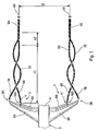
- Figure 1 partially and schematically shows an aircraft, to which applying a device according to the invention.
- Figures 2 and 3 respectively represent two modes of different realization of a means of disturbing a conforming device to the invention.
- Figure 4 is a block diagram showing the main steps the acceleration of the destruction of the vortices, due to the implementation of the process according to the invention.
- the device 1 according to the invention and shown diagrammatically in FIG. 1 is mounted on an airplane 2, in particular an airplane of transport, of which only the two wings 3A and 3B and a part of the fuselage 4, to accelerate the destruction of at least two vortices contra-rotating 5A and 5B which are created respectively in the wake of said wings 3A and 3B and which are separated from each other by a distance inter-vortex D (distance between the centers of the hearts of said vortexes 5A and 5B).
- the vortex 5A is formed at the rear of the wing 3A by fusion at least two co-rotating vortices 7A and 8A, one of which 7A is created by the end 9A of the wing 3A and the other 8A by the end of said flap 6A deployed, each of said co-rotating vortices 7A and 8A having a plurality of modes of instability of the heart, as specified below.
- Said co-rotating vortices 7A and 8A are maintained over a distance L1, before merging over a distance L2.
- the 5B vortex is formed at the rear of wing 3B by the fusion of at least two co-rotating vortices 7B and 8B, one of which 7B is created by the end 9B of the wing 3B and the other 8B by the end of the flap 6B deployed.
- the invention to accelerate the destruction of said 5A vortices and 5B, it generates, at each of said wings 3A and 3B, in the vicinity creation zone 10A, 10B of at least one 8A, 8B of said co-rotating vortices 7A, 8A; 7B, 8B of wing 3A, 3B, a disturbance periodic flow.
- Each of said periodic disturbances has a wavelength which is capable of exciting at least one, but of preferably a plurality of modes of instability of the vortex 8A, 8B corresponding so as to increase the heart of the contra-rotating vortex 5A, 5B which is created from the unstable fusion of this vortex 8A, 8B with the other vortex 7A, 7B so that the diameter dA, dB of said core becomes greater than a predetermined proportion (at least equal to 0.3, preferably) of said inter-vortex distance D.
- a predetermined proportion at least equal to 0.3, preferably
- the device 1 comprises on each of said wings 3A, 3B, at least one disturbance means 11 or 12 specified below, which is arranged in the vicinity of said zone of creation 10A, 10B of one of said co-rotating vortices 8A, 8B of the wing 3A, 3B, that is to say in the vicinity of the end of the flap 6A, 6B in the example of Figure 1, and which is likely to cause said disturbance periodic flow.
- the device 1 therefore generates for each vortex 5A, 5B, a disturbance with a precise wavelength and likely to excite the maximum of unstable modes, in particular of the so-called "elliptical" instability of the corresponding vortex, for example of the flap end swirl 8A 6A in the example of FIG. 1 for wing 3A.
- This disturbance causes the core of said vortex 8A to oscillate and the makes it unstable.
- the latter 8A then presents disturbances of its structure internal.
- the modes of instability of the co-rotating vortices 8A and 8B are determined from theory of known instability, partially presented above, which has been confirmed through simulations and experiments.
- the parameters determining the modes of instability are essentially the size (diameter) of the vortex hearts 7A, 7B, 8A, 8B before fusion and the size ratio of the heart / distance between these vortices.
- the variation in the number of Reynolds (expressing the effect of the viscosity of the fluid) has practically no effect in situations applied to an airplane.
- the most unstable wavelengths of the instability modes can be determined by the theory of elliptical instability, at from the above parameters. However, these predictions only give an order of magnitude for the situation considered.
- the lengths most unstable waveforms are of the order of the mean diameter of the core of the corresponding vortex. Precise values in the situation considered must be found empirically.
- the disturbances to be generated must have wavelengths close to that of the instability mode, or very close to a divider of this one.
- the wavelength of a perturbation at generate is located in an instability band of each of the vortices co-rotating the corresponding wing.
- the device 1 according to the invention has at least two means of disturbance which can be each made according to different embodiments 11, 12.
- said disturbance means 11 includes a non-profiled element 13, the "apparent" or “effective" diameter, transversely to the flow, depends the wavelength of the periodic disturbance to be generated.
- this non-profiled element 13 is a cylinder, for example of circular section, as shown in figure 2.
- this cylinder can also have an elliptical section or even any. It can also be a flat plate with high incidence, for example inclined at 45 °.
- the "effective" transverse dimension (or width) of element 13 therefore determines the wavelength of the perturbation generated.
- This "effective" width depends on the degree of deviation of the current lines by element 13. It is not necessarily identical to the real dimension of element 13. For example, a flat plate, perpendicular to the flow, deviates current lines much more than a cylinder of the same diameter.
- the relationship between "effective" dimension and length wake wave generated is known for a number of elements purely empirically: there is no theoretical result.
- the wavelength is of the order of several times the "effective" width of item. So we can get a rough idea of the dimension of element 13 in advance, but for each form considered, the relation must again be found empirically.
- said element 13 can therefore correspond to any element (not profiled) allowing to generate the disturbance aforementioned periodic flow.
- this element 13 is retractable.
- it is preferably retractable inside wing 3A, 3B or flap 6A, 6B or existing fairings near which it is planned, using means usual retraction not shown. This does not increase the dragged and thus not to decrease the performance of the aircraft 2, in particular in cruise flight.
- said disturbance means 12 includes means 14 for usual type, to produce a jet of fluid 15, as illustrated by arrows 16.
- This jet of fluid 15 is emitted transversely to the flow E so as to generate the perturbation P according to the invention, as partially shown. If said fluid jet 15 is emitted orthogonally at flow E, its speed must be at least equal to that of airplane 2 and its diameter of the same order of magnitude as the apparent diameter of a element 13 not profiled, capable of being used in its place.
- said means 14 is arranged inside the structure 17 existing near said creation zone 10A, 10B, by example inside the shutter 6A, 6B or the wing 3A, 3B. If not in the case, said means 14 can also be retractable.
- the disturbance means 11, 12 must be chosen so as to produce a disturbance with a length wave likely to excite the maximum of unstable modes of instability elliptical co-rotating vortices.
- an example of apparent (transverse) diameter or effective is of the order of 10 cm causing a disturbance having a wavelength of about 50 cm.
- a radius representative of the wing or flap end vortex before fusion can be of the order of 1 meter (m), giving a length maximum wave of elliptical instability of the order of 3 m, at which there is also a multitude of unstable lower wavelengths.
- the perturbation generated by the device 1 is capable of exciting the modes which have the same wavelength, but also all those close to multipies. In the example considered, the disturbance created by the device 1 would excite the wavelength modes 50 cm, 1 m, etc., up to 3 m (beyond, the vortices are stable), so in total a maximum of six unstable modes.
- the device 1 comprises at minus a disturbance means 11, 12 by vortex 5A, 5B.
- a disturbance means 11, 12 by vortex 5A, 5B can also include two (or more), one then acting on the wing tip vortex and the other on the flap end vortex.
- this means of disturbance acts on the vortex 8A, 8B flap end 6A, 6B, which is more energetic due to a distribution of different lift and more favorable to the vortex generation as the end vortex 7A, 7B 9A, 9B of the wing 3A, 3B.
- Said device 1 can of course be used to accelerate the destruction of a number of vortexes greater than two, by providing for a appropriate number of disturbance means 11, 12.
- said device 1 according to the invention is passive, simple, robust and inexpensive.
- the present invention can be applied to any mobile comprising vortices in the wake of its wings (in the broad sense), and in particular to a submarine in order to make its detection, in particular by satellite, more difficult.
Landscapes
- Engineering & Computer Science (AREA)
- Aviation & Aerospace Engineering (AREA)
- Aerodynamic Tests, Hydrodynamic Tests, Wind Tunnels, And Water Tanks (AREA)
- Control Of Position, Course, Altitude, Or Attitude Of Moving Bodies (AREA)
- Stored Programmes (AREA)
- Air Bags (AREA)
- Looms (AREA)
- Tires In General (AREA)
Abstract
Description
- "tourbillons", les phénomènes tourbillonnaires qui existent avant la fusion et qui vont fusionner ensemble ; et
- "vortex", les phénomènes tourbillonnaires obtenus par la fusion d'au moins deux de ces tourbillons.
- est de l'ordre d'un diviseur de la longueur d'onde la plus instable du mode d'instabilité qu'elle doit exciter, ce qui permet de réduire la taille des moyens utilisés pour engendrer ladite perturbation ; et/ou
- est située dans une bande d'instabilité de chacun des tourbillons co-rotatifs de l'aile correspondante.
- dans un premier mode de réalisation, un élément non profilé, par exemple un cylindre, dont le diamètre apparent transversalement à l'écoulement dépend de la longueur d'onde de la perturbation périodique à engendrer ; et
- dans un second mode de réalisation, un moyen pour produire un jet de fluide émis transversalement audit écoulement. Si on émet ledit jet de fluide orthogonalement à l'écoulement, sa vitesse doit être au moins égale à celle du mobile et son diamètre du même ordre de grandeur que le diamètre apparent d'un élément non profilé, susceptible d'être utilisé à sa place.
- en E1A et E1B, sont indiquées les perturbations périodiques précitées engendrées par l'action du dispositif 1, qui correspondent chacune à une instabilité connue sous l'expression d"'instabilité de Bénard-von Kármán" ;
- en E2A et E2B, des instabilités tridimensionnelles du coeur, en particulier
des "instabilités elliptiques", existant dans les tourbillons 8A et
8B sont accrues par les perturbations périodiques engendrées conformément
à l'invention.
On sait que ces instabilités tridimensionnelles se développent dans un tourbillon soumis à un étirement. Ceci arrive dans le cas de paires de tourbillons co-rotatifs (ou contrarotatifs), l'étirement sur chaque tourbillon étant induit par la présence de l'autre tourbillon, ce qui rend instable ledit tourbillon. L'instabilité qui s'ensuit produit des perturbations de la structure interne du tourbillon, avec une longueur d'onde axiale caractéristique de l'ordre du diamètre du coeur du tourbillon.
L'instabilité elliptique a été mise en évidence :- pour les tourbillons contrarotatifs, par Leweke T. et Williamson C.H.K. dans un article intitulé "Cooperative elliptic instability of a vortex pair" et paru dans la publication "J. Fluid Mech", vol. 360, p. 85-119 ; et
- pour les tourbillons co-rotatifs, par Meunier P., Leweke T. et Abid M. dans un article intitulé "Three-dimensional instability of two merging vortices" et paru dans la publication "Advances in Turbulence VIII", CIMNE, p. 15-18.
Le phénomène principal dans l'interaction des tourbillons co-rotatifs (7A et 8A d'une part, 7B et 8B d'autre part) est la fusion des deux tourbillons en un seul vortex 5A, 5B, dès que les rayons des coeurs de ces tourbillons co-rotatifs, qui augmentent au cours du temps par diffusion visqueuse ou turbulente de la vorticité, dépassent une fraction critique de la distance entre les centres des coeurs de ces tourbillons ; - ces fusions, entre 7A et 8A d'une part et entre 7B et 8B d'autre part,
sont réalisées respectivement aux étapes E3A et E3B.
En raison des instabilités (qui ont été amplifiées conformément à l'invention) des tourbillons 8A et 8B, les vortex 5A et 5B qui sont créés par ces fusions instables présentent des diamètres dA et dB plus importants et des niveaux de turbulence interne plus élevés, qu'en l'absence d'amplification.
Selon l'invention, ces diamètres dA et dB sont supérieurs à une proportion déterminée (par exemple 0,3) de la distance inter-vortex D ; et - grâce à l'obtention de diamètres dA et dB vérifiant de telles tailles, le régime non linéaire de l'instabilité entre vortex contrarotatifs provoque (étape E4) un échange de fluide entre les deux vortex 5A et 5B par la création de vortex secondaires à petite échelle, qui sont perpendiculaires aux axes des tourbillons principaux. Cette situation entraíne rapidement une désintégration de la paire initiale de vortex 5A et 5B par un mouvement turbulent du fluide à petite échelle et une diminution importante et rapide de la circulation de chaque vortex. Les vortex 5A et 5B sont donc détruits plus rapidement.
Claims (9)
- Procédé pour accélérer la destruction d'au moins deux vortex contrarotatifs (5A, 5B) qui sont créés respectivement dans le sillage des ailes (3A, 3B) d'un mobile (2) muni d'au moins deux ailes (3A, 3B), dont chaque aile (3A, 3B) est pourvue d'au moins deux surfaces portantes (3A, 6A ; 3B, 6B), et qui sont séparés l'un de l'autre d'une distance inter-vortex (D), chacun desdits vortex contrarotatifs (5A, 5B) étant formé à l'arrière de l'aile correspondante (3A, 3B) par la fusion d'au moins deux tourbillons co-rotatifs (7A, 8A ; 7B, 8B) qui sont créés respectivement par la disposition desdites surfaces portantes (3A, 3B, 6A, 6B) de l'aile (3A, 3B), chacun desdits tourbillons co-rotatifs présentant une pluralité de modes d'instabilité du coeur,
caractérisé en ce que l'on engendre, au niveau de chacune desdites ailes (3A, 3B), au voisinage de la zone de création (10A, 10B) d'au moins l'un desdits tourbillons co-rotatifs (8A, 8B) de l'aile, une perturbation périodique de l'écoulement, et en ce que chacune desdites perturbations périodiques présente une longueur d'onde qui est apte à exciter au moins l'un desdits modes d'instabilité du tourbillon correspondant (8A, 8B) de manière à augmenter le coeur du vortex contrarotatif (5A, 5B) qui est créé à partir de la fusion instable de ce tourbillon (8A, 8B) avec l'autre tourbillon (7A, 7B) de sorte que le diamètre (dA, dB) dudit coeur devienne supérieur à une proportion prédéterminée de ladite distance inter-vortex (D). - Procédé selon la revendication 1,
caractérisé en ce que l'on détermine ledit mode d'instabilité à exciter, à partir de la taille des coeurs des tourbillons (7A, 7B, 8A, 8B) et des rapports entre les tailles des coeurs et la distance entre les tourbillons. - Procédé selon l'une des revendications 1 et 2,
caractérisé en ce que la longueur d'onde du mode d'instabilité est sensiblement égale au diamètre moyen du coeur du tourbillon correspondant (8A, 8B). - Procédé selon l'une des revendications 1 à 3,
caractérisé en ce que la longueur d'onde d'une perturbation périodique à engendrer est de l'ordre d'un diviseur de la longueur d'onde la plus instable du mode d'instabilité, qu'elle doit exciter. - Procédé selon l'une quelconque des revendications 1 à 4,
caractérisé en ce que la longueur d'onde d'une perturbation périodique à engendrer est située dans une bande d'instabilité de chacun des tourbillons co-rotatifs (7A, 8A ; 7B, 8B) de l'aile correspondante (3A, 3B). - Dispositif pour un mobile (2) muni d'au moins deux ailes (3A, 3B), dont chaque aile (3A, 3B) est pourvue d'au moins deux surfaces portantes (3A, 6A ; 3B, 6B), pour accélérer la destruction d'une paire de vortex contrarotatifs (5A, 5B) qui sont créés respectivement dans le sillage desdites ailes (6A, 6B) du mobile (2) et qui sont séparés l'un de l'autre d'une distance inter-vortex (D), chacun desdits vortex contrarotatifs (5A, 5B) étant formé à l'arrière de l'aile correspondante par la fusion d'au moins deux tourbillons co-rotatifs (7A, 8A ; 7B, 8B) qui sont créés respectivement par la disposition desdites surfaces portantes (3A, 3B, 6A, 6B), chacun desdits tourbillons co-rotatifs présentant une pluralité de modes d'instabilité,
caractérisé en ce qu'il comporte, sur chacune desdites ailes (3A, 3B), au moins un moyen de perturbation (11, 12) qui est agencé au voisinage de la zone de création (10A, 10B) de l'un desdits tourbillons co-rotatifs de l'aile, et en ce que chacun desdits moyens de perturbation (11, 12) est susceptible d'engendrer une perturbation périodique de l'écoulement, qui présente une longueur d'onde apte à exciter au moins l'un desdits modes d'instabilité du tourbillon correspondant (8A, 8B) de manière à augmenter le coeur du vortex contrarotatif (5A, 5B) qui est créé à partir de la fusion instable de ce tourbillon (8A, 8B) avec l'autre tourbillon (7A, 7B) de sorte que le diamètre (dA, dB) dudit coeur devienne supérieur à une proportion prédéterminée de ladite distance inter-vortex (D). - Dispositif selon la revendication 6,
caractérisé en ce qu'au moins l'un (11) desdits moyens de perturbation comporte un élément non profilé (13), dont le diamètre apparent transversalement à l'écoulement dépend de la longueur d'onde de la perturbation périodique à engendrer. - Dispositif selon l'une quelconque des revendications 6 et 7,
caractérisé en ce qu'au moins l'un (12) desdits moyens de perturbation comporte un moyen (14) pour produire un jet de fluide (15) émis transversalement audit écoulement (E). - Dispositif selon l'une quelconque des revendications 6 à 8,
caractérisé en ce qu'au moins l'un desdits moyens de perturbation (11, 12) est escamotable.
Applications Claiming Priority (2)
| Application Number | Priority Date | Filing Date | Title |
|---|---|---|---|
| FR0102804 | 2001-03-01 | ||
| FR0102804A FR2821605B1 (fr) | 2001-03-01 | 2001-03-01 | Procede et dispositif pour accelerer la destruction d'au moins deux vortex dans le sillage d'un mobile, en particulier d'un avion |
Publications (2)
| Publication Number | Publication Date |
|---|---|
| EP1236641A1 true EP1236641A1 (fr) | 2002-09-04 |
| EP1236641B1 EP1236641B1 (fr) | 2004-03-17 |
Family
ID=8860614
Family Applications (1)
| Application Number | Title | Priority Date | Filing Date |
|---|---|---|---|
| EP20020290329 Expired - Lifetime EP1236641B1 (fr) | 2001-03-01 | 2002-02-11 | Procédé et dispositif pour accélerer la destruction d'au moins deux vortex dans le sillage d'un mobile, en particulier d'un avion |
Country Status (7)
| Country | Link |
|---|---|
| US (3) | US6719246B2 (fr) |
| EP (1) | EP1236641B1 (fr) |
| AT (1) | ATE261844T1 (fr) |
| CA (1) | CA2370463C (fr) |
| DE (1) | DE60200258T2 (fr) |
| ES (1) | ES2215973T3 (fr) |
| FR (1) | FR2821605B1 (fr) |
Cited By (2)
| Publication number | Priority date | Publication date | Assignee | Title |
|---|---|---|---|---|
| EP1746024A1 (fr) * | 2005-07-22 | 2007-01-24 | Airbus Deutschland GmbH | Procédé de contrôle d'un avion en vol |
| EP2692632A4 (fr) * | 2011-03-30 | 2014-12-31 | Society Of Japanese Aerospace Companies | Dispositif hypersustentateur destiné à un aéronef |
Families Citing this family (10)
| Publication number | Priority date | Publication date | Assignee | Title |
|---|---|---|---|---|
| FR2821605B1 (fr) * | 2001-03-01 | 2003-05-30 | Eads Airbus Sa | Procede et dispositif pour accelerer la destruction d'au moins deux vortex dans le sillage d'un mobile, en particulier d'un avion |
| US20050061921A1 (en) * | 2003-09-19 | 2005-03-24 | Egolf Thomas A. | Aerodynamic tip protuberances for tip vortex intensity reduction |
| US7134631B2 (en) * | 2004-06-10 | 2006-11-14 | Loth John L | Vorticity cancellation at trailing edge for induced drag elimination |
| DE102005025004B4 (de) * | 2005-06-01 | 2010-05-12 | Deutsches Zentrum für Luft- und Raumfahrt e.V. | Verfahren und Vorrichtung zum Abmindern der Zirkulation von Hauptwirbeln in Wirbelschleppen hinter Flugzeugen |
| EP1777523A1 (fr) * | 2005-10-19 | 2007-04-25 | INSERM (Institut National de la Santé et de la Recherche Médicale) | Méthode pour pronostiquer la progression d'un cancer et les résultats du patient et les moyens pour performer la méthode |
| US7740206B2 (en) * | 2006-04-13 | 2010-06-22 | The Board Of Trustees Of The Leland Stanford Junior University | Translating active Gurney flap to alleviate aircraft wake vortex hazard |
| FR2922189B1 (fr) * | 2007-10-16 | 2009-12-18 | Airbus France | Procede et dispositif pour diminuer les vitesses induites dans des tourbillons de sillage d'un avion. |
| US9620025B2 (en) * | 2014-05-01 | 2017-04-11 | The United States Of America As Represented By The Administrator Of The National Aeronautics And Space Administration. | Wake vortex avoidance system and method |
| EP3284667B1 (fr) * | 2016-08-16 | 2019-03-06 | Airbus Operations GmbH | Agencement d'extrémité d'aile ayant des vortilons fixés à une surface inférieure, aéronef comportant un tel agencement d'extrémité et utilisation des vortilons sur une extrémité |
| CN116176162B (zh) * | 2023-01-09 | 2023-08-29 | 武汉理工大学 | 一种动态分裂景观设备 |
Citations (6)
| Publication number | Priority date | Publication date | Assignee | Title |
|---|---|---|---|---|
| US3881669A (en) * | 1973-05-16 | 1975-05-06 | Martin Lessen | Method and apparatus for elimination of airfoil trailing vortices |
| US5492289A (en) | 1992-04-28 | 1996-02-20 | British Technology Group Usa Inc. | Lifting body with reduced-strength trailing vortices |
| WO1999000297A1 (fr) | 1997-06-26 | 1999-01-07 | The Boeing Company | Systeme actif de destruction precoce des tourbillons de sillage |
| US6042059A (en) | 1997-02-20 | 2000-03-28 | Continuum Dynamics, Inc. | System and method of vortex wake control using vortex leveraging |
| DE19909190A1 (de) * | 1999-03-03 | 2000-09-14 | Deutsch Zentr Luft & Raumfahrt | Verfahren und Vorrichtung zum Reduzieren der Wirbelstärke der Flügelhauptwirbel hinter im Flug befindlichen Flugzeugen |
| EP1145954A1 (fr) * | 2000-04-13 | 2001-10-17 | EADS Airbus GmbH | Dispositif et procédé pour la réduction des tourbillons de sillage à l'arrière des avions à l'approche de l'atterissage |
Family Cites Families (47)
| Publication number | Priority date | Publication date | Assignee | Title |
|---|---|---|---|---|
| US2562227A (en) * | 1947-07-09 | 1951-07-31 | Zobel Theodor Wilhelm | Flow profile for reduced drag |
| US2743888A (en) * | 1951-10-20 | 1956-05-01 | Collins Radio Co | Variable wing |
| US3776363A (en) * | 1971-05-10 | 1973-12-04 | A Kuethe | Control of noise and instabilities in jet engines, compressors, turbines, heat exchangers and the like |
| US3904151A (en) * | 1973-03-16 | 1975-09-09 | Vehicle Research Corp | Supersonic upflow wing |
| JPS587830B2 (ja) * | 1973-04-27 | 1983-02-12 | 株式会社日立製作所 | リユウタイチユウニ オケル ブツタイノ カリユウガワタンブノ ケイジヨウ |
| US3974986A (en) * | 1973-05-29 | 1976-08-17 | Johnstone Edmund H | Aircraft wing vortex deflector |
| US3936013A (en) * | 1973-12-17 | 1976-02-03 | Shao Wen Yuan | Vortex control |
| US3984070A (en) * | 1974-05-24 | 1976-10-05 | The United States Of America As Represented By The Administrator Of The National Aeronautics And Space Administration | Wingtip vortex dissipator for aircraft |
| US4046336A (en) * | 1975-05-13 | 1977-09-06 | Textron, Inc. | Vortex diffusion and dissipation |
| US4117995A (en) * | 1977-02-28 | 1978-10-03 | Runge Thomas M | Aircraft wing lift augmentation device |
| US4323209A (en) * | 1977-07-18 | 1982-04-06 | Thompson Roger A | Counter-rotating vortices generator for an aircraft wing |
| US4176813A (en) * | 1977-10-05 | 1979-12-04 | Northrop Corporation | Shark nose for aircraft |
| US4377267A (en) * | 1981-01-12 | 1983-03-22 | Juanita June Haworth | Vortex tranquilizer |
| US4477042A (en) * | 1981-01-19 | 1984-10-16 | Griswold Ii Roger W | Vortex alleviating wing tip |
| GB8310224D0 (en) * | 1983-04-15 | 1983-05-18 | British Aerospace | Wing tip arrangement |
| US4705240A (en) * | 1984-05-14 | 1987-11-10 | Dixon Charles J | Passive vortex lift control |
| US4671473A (en) * | 1984-11-08 | 1987-06-09 | Goodson Kenneth W | Airfoil |
| US5209438A (en) * | 1988-06-20 | 1993-05-11 | Israel Wygnanski | Method and apparatus for delaying the separation of flow from a solid surface |
| US5340054A (en) * | 1991-02-20 | 1994-08-23 | The United States Of America As Represented By The Secretary Of The Navy | Suppressor of oscillations in airframe cavities |
| US5205519A (en) * | 1992-01-07 | 1993-04-27 | The United States Of America As Represented By The United States National Aeronautics And Space Administration | Boundary layer relaminarization device |
| US5255881A (en) * | 1992-03-25 | 1993-10-26 | Vigyan, Inc. | Lift augmentation for highly swept wing aircraft |
| US5253828A (en) * | 1992-07-17 | 1993-10-19 | The Board Of Regents Of The University Of Oklahoma | Concealable flap-actuated vortex generator |
| US5520356A (en) * | 1992-08-14 | 1996-05-28 | Ensley; Donald L. | System for propelling and guiding a solid object with a beam of electromagnetic radiation |
| US5588620A (en) * | 1992-08-26 | 1996-12-31 | Gilbert; Raymond D. | Radial-force spoiler system |
| ES2064261B1 (es) * | 1993-02-25 | 1998-07-16 | Doria Iriarte Jose Javier | Fuselaje mejorado a fin de lograr efectos de estabilizacion de torbellinos. |
| US5564656A (en) * | 1994-08-29 | 1996-10-15 | Gilbert; Raymond D. | Segmented spoilers |
| US5692709A (en) * | 1994-11-01 | 1997-12-02 | Condor Systems, Inc. | Shock wave stabilization apparatus and method |
| US5598990A (en) * | 1994-12-15 | 1997-02-04 | University Of Kansas Center For Research Inc. | Supersonic vortex generator |
| US5755408A (en) * | 1995-04-03 | 1998-05-26 | Schmidt; Robert N. | Fluid flow control devices |
| US5806807A (en) * | 1995-10-04 | 1998-09-15 | Haney; William R. | Airfoil vortex attenuation apparatus and method |
| IL119392A (en) * | 1996-10-09 | 2004-01-04 | Rafael Armament Dev Authority | Device for reducing the drag at the base of a body |
| US6092990A (en) * | 1997-06-05 | 2000-07-25 | Mcdonnell Douglas Helicopter Company | Oscillating air jets for helicopter rotor aerodynamic control and BVI noise reduction |
| IL121164A (en) * | 1997-06-26 | 2002-03-10 | Univ Ramot | Airfoil with dynamic stall control by oscillatory forcing |
| WO1999044887A1 (fr) * | 1998-03-06 | 1999-09-10 | Batcho Paul F | Procede et appareil d'attenuation des ecoulements aux jonctions |
| FR2782307B1 (fr) * | 1998-08-17 | 2000-10-13 | Onera (Off Nat Aerospatiale) | Procede pour la reduction du bruit d'interaction pales-tourbillons engendre par une voilure tournante |
| DE19926832B4 (de) * | 1999-06-12 | 2005-09-15 | Airbus Deutschland Gmbh | Unterschallflugzeug vorzugsweise mit gepfeilten Tragflügeln |
| US6296202B1 (en) * | 2000-02-09 | 2001-10-02 | The United States Of America As Represented By The Secretary Of The Air Force | Aircraft weapons bay acoustic suppression apparatus |
| JP4535550B2 (ja) * | 2000-02-23 | 2010-09-01 | 富士重工業株式会社 | 回転翼航空機の回転翼羽根 |
| DE10019185C2 (de) * | 2000-04-17 | 2003-06-05 | Airbus Gmbh | Anordnung zur aerodynamischen Lärmminderung von Vorflügeln eines Verkehrsflugzeuges |
| US6484971B2 (en) * | 2000-07-24 | 2002-11-26 | Thombi Layukallo | Control of flow separation and related phenomena on aerodynamic surfaces |
| US6394397B1 (en) * | 2000-12-06 | 2002-05-28 | The Boeing Company | Lifting surface with active variable tip member and method for influencing lifting surface behavior therewith |
| FR2821605B1 (fr) * | 2001-03-01 | 2003-05-30 | Eads Airbus Sa | Procede et dispositif pour accelerer la destruction d'au moins deux vortex dans le sillage d'un mobile, en particulier d'un avion |
| WO2002072421A2 (fr) * | 2001-03-10 | 2002-09-19 | Georgia Tech Research Corporation | Modification de l'ecoulement dun fluide sur des corps et des surfaces par formage aerodynamique virtuel de profils au moyen d'actuateurs de jets synthetiques |
| DE10125905C1 (de) * | 2001-05-28 | 2002-11-28 | Infineon Technologies Ag | Lösbare Verbindung zwischen einem ungehäusten Chip und einem Träger |
| DE10147827A1 (de) * | 2001-09-27 | 2003-04-24 | Airbus Gmbh | Vorrichtung zur Änderung der Quertriebsgröße eines Flugzeughauptelementes mit vorzugsweise flächenförmiger Hinterkante |
| US6837465B2 (en) * | 2003-01-03 | 2005-01-04 | Orbital Research Inc | Flow control device and method of controlling flow |
| US6739554B1 (en) * | 2003-06-02 | 2004-05-25 | The United States Of America As Represented By The Secretary Of The Air Force | Aircraft weapons bay acoustic resonance suppression system |
-
2001
- 2001-03-01 FR FR0102804A patent/FR2821605B1/fr not_active Expired - Lifetime
-
2002
- 2002-02-05 CA CA002370463A patent/CA2370463C/fr not_active Expired - Lifetime
- 2002-02-11 EP EP20020290329 patent/EP1236641B1/fr not_active Expired - Lifetime
- 2002-02-11 DE DE60200258T patent/DE60200258T2/de not_active Expired - Lifetime
- 2002-02-11 AT AT02290329T patent/ATE261844T1/de not_active IP Right Cessation
- 2002-02-11 ES ES02290329T patent/ES2215973T3/es not_active Expired - Lifetime
- 2002-02-25 US US10/080,407 patent/US6719246B2/en not_active Expired - Fee Related
-
2003
- 2003-11-21 US US10/717,672 patent/US20050006533A1/en not_active Abandoned
- 2003-11-21 US US10/717,465 patent/US20040256521A1/en not_active Abandoned
Patent Citations (6)
| Publication number | Priority date | Publication date | Assignee | Title |
|---|---|---|---|---|
| US3881669A (en) * | 1973-05-16 | 1975-05-06 | Martin Lessen | Method and apparatus for elimination of airfoil trailing vortices |
| US5492289A (en) | 1992-04-28 | 1996-02-20 | British Technology Group Usa Inc. | Lifting body with reduced-strength trailing vortices |
| US6042059A (en) | 1997-02-20 | 2000-03-28 | Continuum Dynamics, Inc. | System and method of vortex wake control using vortex leveraging |
| WO1999000297A1 (fr) | 1997-06-26 | 1999-01-07 | The Boeing Company | Systeme actif de destruction precoce des tourbillons de sillage |
| DE19909190A1 (de) * | 1999-03-03 | 2000-09-14 | Deutsch Zentr Luft & Raumfahrt | Verfahren und Vorrichtung zum Reduzieren der Wirbelstärke der Flügelhauptwirbel hinter im Flug befindlichen Flugzeugen |
| EP1145954A1 (fr) * | 2000-04-13 | 2001-10-17 | EADS Airbus GmbH | Dispositif et procédé pour la réduction des tourbillons de sillage à l'arrière des avions à l'approche de l'atterissage |
Non-Patent Citations (3)
| Title |
|---|
| DOYLE A: "BOEING TECHNIQUE LEAVES TRAILING VORTICES BEHIND", FLIGHT INTERNATIONAL, REED BUSINESS INFORMATION, HAYWARDS HEATH, GB, vol. 156, no. 4700, 27 October 1999 (1999-10-27), pages 12, XP000854006, ISSN: 0015-3710 * |
| LEWEKE T, WILLIAMSON C H K: "Cooperative elliptic instability of a vortex pair", JOURNAL OF FLUID DYNAMICS, vol. 360, 10 April 1998 (1998-04-10), pages 85 - 119, XP001039832 * |
| MEUNIER P, LEWEKE T, ABID M: "Three-dimensional instability of two merging vortices", ADVANCES IN TURBULENCE VIII, 2000, pages 15 - 18, XP001039909 * |
Cited By (4)
| Publication number | Priority date | Publication date | Assignee | Title |
|---|---|---|---|---|
| EP1746024A1 (fr) * | 2005-07-22 | 2007-01-24 | Airbus Deutschland GmbH | Procédé de contrôle d'un avion en vol |
| US7874523B2 (en) | 2005-07-22 | 2011-01-25 | Airbus Deutschland Gmbh | Method of controlling an aircraft in flight, especially to reduce wake vortices |
| US8118263B2 (en) | 2005-07-22 | 2012-02-21 | Airbus Operations Gmbh | Method of controlling an aircraft in flight, especially to reduce wake vortices |
| EP2692632A4 (fr) * | 2011-03-30 | 2014-12-31 | Society Of Japanese Aerospace Companies | Dispositif hypersustentateur destiné à un aéronef |
Also Published As
| Publication number | Publication date |
|---|---|
| US20020121576A1 (en) | 2002-09-05 |
| CA2370463C (fr) | 2009-05-12 |
| FR2821605B1 (fr) | 2003-05-30 |
| CA2370463A1 (fr) | 2002-09-01 |
| DE60200258D1 (de) | 2004-04-22 |
| DE60200258T2 (de) | 2005-03-03 |
| US20040256521A1 (en) | 2004-12-23 |
| EP1236641B1 (fr) | 2004-03-17 |
| US20050006533A1 (en) | 2005-01-13 |
| US6719246B2 (en) | 2004-04-13 |
| ATE261844T1 (de) | 2004-04-15 |
| ES2215973T3 (es) | 2004-10-16 |
| FR2821605A1 (fr) | 2002-09-06 |
Similar Documents
| Publication | Publication Date | Title |
|---|---|---|
| EP1236641B1 (fr) | Procédé et dispositif pour accélerer la destruction d'au moins deux vortex dans le sillage d'un mobile, en particulier d'un avion | |
| EP1456081B1 (fr) | Extremite d'aile cylindrique a fente helicoidale | |
| CA2659499C (fr) | Helicoptere hybride rapide a grande distance franchissable | |
| EP0048649B1 (fr) | Profil de pale pour voilure tournante d'aéronef | |
| FR2993859A1 (fr) | Avion multiplans a propulsion pousse et tire | |
| EP3118112A1 (fr) | Aeronef combine muni d'un dispositif anticouple complementaire | |
| EP2212193B1 (fr) | Procédé et dispositif pour diminuer les vitesses induites dans des tourbillons de sillage d'un avion | |
| FR2510066A1 (fr) | Pale aerodynamique | |
| FR2600036A1 (fr) | Dispositif directionnel et stabilisateur a rotor anti-couple carene et incline et a empennage en " v " dissymetrique, et helicoptere equipe d'un tel dispositif. | |
| WO2018197772A1 (fr) | Aéronef à voilure rhomboédrique à décollage et/ou atterrissage vertical | |
| EP3527491A1 (fr) | Methode d'amelioration d'une pale afin d'augmenter son incidence negative de decrochage | |
| EP3365226B1 (fr) | Aeronef a voilure fixe et a stabilite statique accrue | |
| WO2000063071A1 (fr) | Surface aerodynamique d'aeronef a deflecteur de bord de fuite | |
| FR2628062A1 (fr) | Pale pour helice carenee a hautes performances, helice carenee multipale pourvue de telles pales et agencement de rotor de queue a helice carenee pour aeronef a voilure tournante | |
| CA3162013A1 (fr) | Aeronef a propulsion electrique comportant une aile centrale et deux ailes laterales mobiles en rotation | |
| WO1999024317A1 (fr) | Procede de commande des gouvernes d'un avion pour agir contre une deviation laterale de trajectoire au sol | |
| FR3074477A1 (fr) | Avion a configuration evolutive en vol | |
| CA2620510A1 (fr) | Dispositif de controle d'un sillage tourbillonnaire engendre par un element oblong sur l'extrados d'une surface portante d'un aeronef | |
| CA2714815C (fr) | Dispositif anticouple d'un giravion | |
| FR3075169B1 (fr) | Avion a configuration evolutive en vol | |
| FR3054690A1 (fr) | Procede d'optimisation des sections d'une poutre de queue destinee a un aeronef a voilure tournante | |
| WO2025022061A1 (fr) | Propulseur aeronautique non-caréné pour aéronef | |
| FR3102973A1 (fr) | Procédé d’atténuation d’instabilités aéroélastiques dans des avions à fonctionnement transsonique et avion équipé de dispositifs de mise en œuvre du procédé par intervention directe dans la couche limite aérodynamique | |
| WO2024074543A1 (fr) | Aéronef à décollage et atterrissage vertical | |
| FR2681832A1 (fr) | Dispositif de gouvernes d'avion a geometrie variable. |
Legal Events
| Date | Code | Title | Description |
|---|---|---|---|
| PUAI | Public reference made under article 153(3) epc to a published international application that has entered the european phase |
Free format text: ORIGINAL CODE: 0009012 |
|
| AK | Designated contracting states |
Kind code of ref document: A1 Designated state(s): AT BE CH CY DE DK ES FI FR GB GR IE IT LI LU MC NL PT SE TR |
|
| AX | Request for extension of the european patent |
Free format text: AL;LT;LV;MK;RO;SI |
|
| 17P | Request for examination filed |
Effective date: 20021004 |
|
| 17Q | First examination report despatched |
Effective date: 20021216 |
|
| AKX | Designation fees paid |
Designated state(s): AT BE CH CY DE DK ES FI FR GB GR IE IT LI LU MC NL PT SE TR |
|
| GRAP | Despatch of communication of intention to grant a patent |
Free format text: ORIGINAL CODE: EPIDOSNIGR1 |
|
| GRAS | Grant fee paid |
Free format text: ORIGINAL CODE: EPIDOSNIGR3 |
|
| GRAA | (expected) grant |
Free format text: ORIGINAL CODE: 0009210 |
|
| AK | Designated contracting states |
Kind code of ref document: B1 Designated state(s): AT BE CH CY DE DK ES FI FR GB GR IE IT LI LU MC NL PT SE TR |
|
| PG25 | Lapsed in a contracting state [announced via postgrant information from national office to epo] |
Ref country code: NL Free format text: LAPSE BECAUSE OF FAILURE TO SUBMIT A TRANSLATION OF THE DESCRIPTION OR TO PAY THE FEE WITHIN THE PRESCRIBED TIME-LIMIT Effective date: 20040317 Ref country code: FI Free format text: LAPSE BECAUSE OF FAILURE TO SUBMIT A TRANSLATION OF THE DESCRIPTION OR TO PAY THE FEE WITHIN THE PRESCRIBED TIME-LIMIT Effective date: 20040317 Ref country code: TR Free format text: LAPSE BECAUSE OF FAILURE TO SUBMIT A TRANSLATION OF THE DESCRIPTION OR TO PAY THE FEE WITHIN THE PRESCRIBED TIME-LIMIT Effective date: 20040317 Ref country code: AT Free format text: LAPSE BECAUSE OF FAILURE TO SUBMIT A TRANSLATION OF THE DESCRIPTION OR TO PAY THE FEE WITHIN THE PRESCRIBED TIME-LIMIT Effective date: 20040317 Ref country code: IE Free format text: LAPSE BECAUSE OF FAILURE TO SUBMIT A TRANSLATION OF THE DESCRIPTION OR TO PAY THE FEE WITHIN THE PRESCRIBED TIME-LIMIT Effective date: 20040317 |
|
| REG | Reference to a national code |
Ref country code: GB Ref legal event code: FG4D Free format text: NOT ENGLISH |
|
| REG | Reference to a national code |
Ref country code: CH Ref legal event code: EP |
|
| REG | Reference to a national code |
Ref country code: IE Ref legal event code: FG4D Free format text: FRENCH |
|
| REF | Corresponds to: |
Ref document number: 60200258 Country of ref document: DE Date of ref document: 20040422 Kind code of ref document: P |
|
| GBT | Gb: translation of ep patent filed (gb section 77(6)(a)/1977) |
Effective date: 20040415 |
|
| PG25 | Lapsed in a contracting state [announced via postgrant information from national office to epo] |
Ref country code: GR Free format text: LAPSE BECAUSE OF FAILURE TO SUBMIT A TRANSLATION OF THE DESCRIPTION OR TO PAY THE FEE WITHIN THE PRESCRIBED TIME-LIMIT Effective date: 20040617 Ref country code: DK Free format text: LAPSE BECAUSE OF FAILURE TO SUBMIT A TRANSLATION OF THE DESCRIPTION OR TO PAY THE FEE WITHIN THE PRESCRIBED TIME-LIMIT Effective date: 20040617 Ref country code: SE Free format text: LAPSE BECAUSE OF FAILURE TO SUBMIT A TRANSLATION OF THE DESCRIPTION OR TO PAY THE FEE WITHIN THE PRESCRIBED TIME-LIMIT Effective date: 20040617 |
|
| NLV1 | Nl: lapsed or annulled due to failure to fulfill the requirements of art. 29p and 29m of the patents act | ||
| REG | Reference to a national code |
Ref country code: ES Ref legal event code: FG2A Ref document number: 2215973 Country of ref document: ES Kind code of ref document: T3 |
|
| REG | Reference to a national code |
Ref country code: IE Ref legal event code: FD4D |
|
| PLBE | No opposition filed within time limit |
Free format text: ORIGINAL CODE: 0009261 |
|
| STAA | Information on the status of an ep patent application or granted ep patent |
Free format text: STATUS: NO OPPOSITION FILED WITHIN TIME LIMIT |
|
| PG25 | Lapsed in a contracting state [announced via postgrant information from national office to epo] |
Ref country code: CY Free format text: LAPSE BECAUSE OF FAILURE TO SUBMIT A TRANSLATION OF THE DESCRIPTION OR TO PAY THE FEE WITHIN THE PRESCRIBED TIME-LIMIT Effective date: 20050211 Ref country code: LU Free format text: LAPSE BECAUSE OF NON-PAYMENT OF DUE FEES Effective date: 20050211 |
|
| PG25 | Lapsed in a contracting state [announced via postgrant information from national office to epo] |
Ref country code: BE Free format text: LAPSE BECAUSE OF NON-PAYMENT OF DUE FEES Effective date: 20050228 Ref country code: MC Free format text: LAPSE BECAUSE OF NON-PAYMENT OF DUE FEES Effective date: 20050228 |
|
| 26N | No opposition filed |
Effective date: 20041220 |
|
| BERE | Be: lapsed |
Owner name: CENTRE NATIONAL DE LA RECHERCHE SCIENTIFIQUE *CNRS Effective date: 20050228 Owner name: SOC. CIVILE CERFACS *CENTRE EUROPEEN DE RECHERCHE Effective date: 20050228 Owner name: *AIRBUS FRANCE Effective date: 20050228 |
|
| PG25 | Lapsed in a contracting state [announced via postgrant information from national office to epo] |
Ref country code: FR Free format text: LAPSE BECAUSE OF NON-PAYMENT OF DUE FEES Effective date: 20051031 |
|
| REG | Reference to a national code |
Ref country code: FR Ref legal event code: ST Effective date: 20051031 |
|
| PG25 | Lapsed in a contracting state [announced via postgrant information from national office to epo] |
Ref country code: LI Free format text: LAPSE BECAUSE OF NON-PAYMENT OF DUE FEES Effective date: 20060228 Ref country code: CH Free format text: LAPSE BECAUSE OF NON-PAYMENT OF DUE FEES Effective date: 20060228 |
|
| REG | Reference to a national code |
Ref country code: CH Ref legal event code: PL |
|
| BERE | Be: lapsed |
Owner name: CENTRE NATIONAL DE LA RECHERCHE SCIENTIFIQUE *CNRS Effective date: 20050228 Owner name: SOC. CIVILE CERFACS *CENTRE EUROPEEN DE RECHERCHE Effective date: 20050228 Owner name: *AIRBUS FRANCE Effective date: 20050228 |
|
| PG25 | Lapsed in a contracting state [announced via postgrant information from national office to epo] |
Ref country code: PT Free format text: LAPSE BECAUSE OF NON-PAYMENT OF DUE FEES Effective date: 20040817 |
|
| REG | Reference to a national code |
Ref country code: GB Ref legal event code: 732E Free format text: REGISTERED BETWEEN 20110721 AND 20110727 |
|
| REG | Reference to a national code |
Ref country code: ES Ref legal event code: PC2A Owner name: AIRBUS OPERATIONS SAS Effective date: 20120210 |
|
| REG | Reference to a national code |
Ref country code: DE Ref legal event code: R082 Ref document number: 60200258 Country of ref document: DE Representative=s name: MEISSNER & MEISSNER, DE |
|
| REG | Reference to a national code |
Ref country code: DE Ref legal event code: R081 Ref document number: 60200258 Country of ref document: DE Owner name: SOCIETE CIVILE CERFACS (CENTRE EUROPEEN DE REC, FR Free format text: FORMER OWNER: AIRBUS FRANCE, CENTRE NATIONAL DE LA RECHERCHE, SOCIETE CIVILE CERFACS (CENTRE, , FR Effective date: 20120326 Ref country code: DE Ref legal event code: R081 Ref document number: 60200258 Country of ref document: DE Owner name: CENTRE NATIONAL DE LA RECHERCHE SCIENTIFIQUE (, FR Free format text: FORMER OWNER: AIRBUS FRANCE, CENTRE NATIONAL DE LA RECHERCHE, SOCIETE CIVILE CERFACS (CENTRE, , FR Effective date: 20120326 Ref country code: DE Ref legal event code: R081 Ref document number: 60200258 Country of ref document: DE Owner name: AIRBUS OPERATIONS SAS, FR Free format text: FORMER OWNER: AIRBUS FRANCE, CENTRE NATIONAL DE LA RECHERCHE, SOCIETE CIVILE CERFACS (CENTRE, , FR Effective date: 20120326 Ref country code: DE Ref legal event code: R082 Ref document number: 60200258 Country of ref document: DE Representative=s name: MEISSNER & MEISSNER, DE Effective date: 20120326 Ref country code: DE Ref legal event code: R081 Ref document number: 60200258 Country of ref document: DE Owner name: SOCIETE CIVILE CERFACS (CENTRE EUROPEEN DE REC, FR Free format text: FORMER OWNERS: AIRBUS FRANCE, TOULOUSE, FR; CENTRE NATIONAL DE LA RECHERCHE SCIENTIFIQUE (C.N.R.S.), PARIS, FR; SOCIETE CIVILE CERFACS (CENTRE EUROPEEN DE RECHERCHE ET DE FORMATION AVANCEE EN, TOULOUSE, FR Effective date: 20120326 Ref country code: DE Ref legal event code: R081 Ref document number: 60200258 Country of ref document: DE Owner name: CENTRE NATIONAL DE LA RECHERCHE SCIENTIFIQUE (, FR Free format text: FORMER OWNERS: AIRBUS FRANCE, TOULOUSE, FR; CENTRE NATIONAL DE LA RECHERCHE SCIENTIFIQUE (C.N.R.S.), PARIS, FR; SOCIETE CIVILE CERFACS (CENTRE EUROPEEN DE RECHERCHE ET DE FORMATION AVANCEE EN, TOULOUSE, FR Effective date: 20120326 Ref country code: DE Ref legal event code: R082 Ref document number: 60200258 Country of ref document: DE Representative=s name: ANWALTSKANZLEI MEISSNER & MEISSNER, DE Effective date: 20120326 Ref country code: DE Ref legal event code: R081 Ref document number: 60200258 Country of ref document: DE Owner name: AIRBUS OPERATIONS SAS, FR Free format text: FORMER OWNERS: AIRBUS FRANCE, TOULOUSE, FR; CENTRE NATIONAL DE LA RECHERCHE SCIENTIFIQUE (C.N.R.S.), PARIS, FR; SOCIETE CIVILE CERFACS (CENTRE EUROPEEN DE RECHERCHE ET DE FORMATION AVANCEE EN, TOULOUSE, FR Effective date: 20120326 |
|
| PGFP | Annual fee paid to national office [announced via postgrant information from national office to epo] |
Ref country code: IT Payment date: 20210222 Year of fee payment: 20 |
|
| PGFP | Annual fee paid to national office [announced via postgrant information from national office to epo] |
Ref country code: DE Payment date: 20210217 Year of fee payment: 20 Ref country code: GB Payment date: 20210219 Year of fee payment: 20 |
|
| PGFP | Annual fee paid to national office [announced via postgrant information from national office to epo] |
Ref country code: ES Payment date: 20210421 Year of fee payment: 20 |
|
| REG | Reference to a national code |
Ref country code: DE Ref legal event code: R071 Ref document number: 60200258 Country of ref document: DE |
|
| REG | Reference to a national code |
Ref country code: GB Ref legal event code: PE20 Expiry date: 20220210 |
|
| PG25 | Lapsed in a contracting state [announced via postgrant information from national office to epo] |
Ref country code: GB Free format text: LAPSE BECAUSE OF EXPIRATION OF PROTECTION Effective date: 20220210 |
|
| REG | Reference to a national code |
Ref country code: ES Ref legal event code: FD2A Effective date: 20220526 |
|
| PG25 | Lapsed in a contracting state [announced via postgrant information from national office to epo] |
Ref country code: ES Free format text: LAPSE BECAUSE OF EXPIRATION OF PROTECTION Effective date: 20220212 |