EP1236593B1 - Air conditioner and device for regulating the thermal comfort in a vehicle - Google Patents
Air conditioner and device for regulating the thermal comfort in a vehicle Download PDFInfo
- Publication number
- EP1236593B1 EP1236593B1 EP20020000916 EP02000916A EP1236593B1 EP 1236593 B1 EP1236593 B1 EP 1236593B1 EP 20020000916 EP20020000916 EP 20020000916 EP 02000916 A EP02000916 A EP 02000916A EP 1236593 B1 EP1236593 B1 EP 1236593B1
- Authority
- EP
- European Patent Office
- Prior art keywords
- air
- conditioner according
- temperature
- temperature sensor
- outflow
- Prior art date
- Legal status (The legal status is an assumption and is not a legal conclusion. Google has not performed a legal analysis and makes no representation as to the accuracy of the status listed.)
- Expired - Lifetime
Links
Images


Classifications
-
- B—PERFORMING OPERATIONS; TRANSPORTING
- B60—VEHICLES IN GENERAL
- B60H—ARRANGEMENTS OF HEATING, COOLING, VENTILATING OR OTHER AIR-TREATING DEVICES SPECIALLY ADAPTED FOR PASSENGER OR GOODS SPACES OF VEHICLES
- B60H1/00—Heating, cooling or ventilating [HVAC] devices
- B60H1/00642—Control systems or circuits; Control members or indication devices for heating, cooling or ventilating devices
- B60H1/00814—Control systems or circuits characterised by their output, for controlling particular components of the heating, cooling or ventilating installation
- B60H1/00821—Control systems or circuits characterised by their output, for controlling particular components of the heating, cooling or ventilating installation the components being ventilating, air admitting or air distributing devices
- B60H1/00871—Air directing means, e.g. blades in an air outlet
-
- B—PERFORMING OPERATIONS; TRANSPORTING
- B60—VEHICLES IN GENERAL
- B60H—ARRANGEMENTS OF HEATING, COOLING, VENTILATING OR OTHER AIR-TREATING DEVICES SPECIALLY ADAPTED FOR PASSENGER OR GOODS SPACES OF VEHICLES
- B60H1/00—Heating, cooling or ventilating [HVAC] devices
- B60H1/00642—Control systems or circuits; Control members or indication devices for heating, cooling or ventilating devices
- B60H1/00735—Control systems or circuits characterised by their input, i.e. by the detection, measurement or calculation of particular conditions, e.g. signal treatment, dynamic models
- B60H1/00742—Control systems or circuits characterised by their input, i.e. by the detection, measurement or calculation of particular conditions, e.g. signal treatment, dynamic models by detection of the vehicle occupants' presence; by detection of conditions relating to the body of occupants, e.g. using radiant heat detectors
-
- B—PERFORMING OPERATIONS; TRANSPORTING
- B60—VEHICLES IN GENERAL
- B60H—ARRANGEMENTS OF HEATING, COOLING, VENTILATING OR OTHER AIR-TREATING DEVICES SPECIALLY ADAPTED FOR PASSENGER OR GOODS SPACES OF VEHICLES
- B60H1/00—Heating, cooling or ventilating [HVAC] devices
- B60H1/00642—Control systems or circuits; Control members or indication devices for heating, cooling or ventilating devices
- B60H1/00735—Control systems or circuits characterised by their input, i.e. by the detection, measurement or calculation of particular conditions, e.g. signal treatment, dynamic models
- B60H1/00792—Arrangement of detectors
Definitions
- the invention relates to an air conditioner and a device for controlling the thermal comfort in a motor vehicle according to the preamble of claim 1 and an air conditioner with such a device.
- a major shortcoming of today's air conditioning systems which operate with a temperature sensor fixed in one place, is that the time to reach a comfort state, measured by the average travel times, is too long.
- These sensors are usually arranged in the control of the air conditioning and there is a calculation of the headspace temperature.
- high amounts of air are blown into the vehicle interior at a very low temperature.
- the areas of the body lying in the outlet cone of the outlets are excessively cooled, while other parts of the body which are exposed to full solar radiation are heated very strongly.
- train effects can even lead to health problems.
- an additional solar sensor does not take into account the very different long-wave infrared radiation emanating from the inner surfaces and internals, and the inhomogeneities by different shadowing and Heilausströmraumen the nozzles, which can lead to train effects.
- the solar sensor measures only the disturbance variable (sun), but not the effect of the disturbance variable and the enclosing surfaces on the occupants of the vehicle.
- thermopile sensor eg thermopile sensor
- thermal inhomogeneities caused by the temporally and spatially constantly varying radiation distributions on the surface of the occupants should be detected and compensated.
- train effects for example by locally strong cooling by too cold air, should be avoided.
- Another object of the invention is to minimize the required cooling capacity to achieve improved comfort and to save fuel.
- the creation of individual occupant microclimate zones and the regulation of the air temperature and / or the amount of air in each Kimazone optionally separate.
- the device for controlling the thermal comfort has on the one hand at least one of a spatially extending measuring surface detecting Temperature sensor and an outflow for the directional outflow of air conditioned in an air conditioner in an outflow region, wherein according to the invention the detected by the temperature sensor measuring surface of the predetermined by the orientation of the Ausströmers Heilanström measurements corresponds approximately.
- the temperature of the detected area including all external influences, such as solar radiation, shadowing, etc. is enabled, and it is always the correct comfort relevant surface temperature achieved.
- a direct air conditioning of the occupants can be carried out with subtle diffuse or direct rather jet-shaped air currents, since a change in conditions, such as changing solar radiation, drifting, such as lowering or increasing, the comfort surface temperature is detected immediately and intervened control technology can be.
- This direct air conditioning can be both jet-shaped so with high flow rate as well as subtly diffuse.
- diffused flow is meant that air exits the discharge nozzles large cross-section at low speeds or the air in the outlet nozzles divergent or fanned out and loses much of its kinetic energy when flowing into the passenger compartment.
- the passenger air is discreetly displaced or the air of the passenger compartment is mixed into the diffuse air flow.
- the direct air conditioning is accomplished via diffuse vents.
- the measured surface temperature of at least one climate zone is used to change the type of air outflow in at least one climate zone from jet to diffuse.
- a direct jet-shaped air conditioning makes sense, while close to the comfort state rather a diffuse air conditioning is perceived as pleasant.
- Another advantage is also that the direct air conditioning of each micro-climate zone quickly detects the direct effect of the blown air on the measured surface temperature signal. This allows very fast changing conditions can be corrected in a very short time.
- the temperature sensor and the air vent are very close to each other or even form a structural unit.
- the detection direction of the temperature sensor and the outflow of the outflow are then simultaneously adjustable and always exactly matched.
- the vent on air guide elements for flow direction wherein the surface temperature of the non-contact measuring sensor on at least one the spoiler elements is attached. This ensures in the simplest way that this non-contact measuring temperature sensor and the vent are aligned on the same surface.
- the non-contact measuring temperature sensor consists of a thermopile element.
- the outflow may be simple, with the opening angle of the sensor or of the surface directly controllable by it being 30 ° to 120 ° , Preferably about 60 °, so that can be dispensed with a costly optics and the diameter of the area detected by the sensor corresponds approximately to the diameter of the ventilated area and equal to the distance of the object flown to the vent.
- the acted upon by the vent and detected by the temperature sensor solid angle range is not rotationally symmetrical but z. B. be oval in order to better reflect the entire surface area of a vehicle occupant to be tempered.
- thermopile sensors By means of thermopile sensors or other similarly operating sensors, the amounts of air and / or the air temperatures at the individual exhaust nozzles can be regulated so that the surface temperatures achieved in the individual microclimate zones can be converted into a comfortable range. This can be done, for example, that the air flow and / or air temperature at the center nozzle and the side nozzle substantially every occupant or substantially every seat position is regulated in the same way or side and center nozzles of each seat position or each occupant differently tempered air and / or blows out different amounts of air to cope with and compensate for the direction of the disturbance, such as solar radiation.
- each occupant or each seating position at least one sensor, such as thermopile sensor, is assigned, which is preferably arranged in the exhaust nozzles or in the vicinity of the exhaust nozzles. Depending on the embodiment, it can also be placed elsewhere, such as in an A-pillar, in the operating element, on the dashboard or in the headliner.
- sensors such as thermopile sensor
- micro-climate zone is monitored by its own sensor. It is also possible to calculate the temperatures in microclimate zones by means of temperature sensors or thermocouples, which are assigned to other climatic zones. For the rear ventilation, the signals from sensors of the front seat positions or occupants could preferably be used.
- each seat position or each occupant is air-conditioned directly to at least one air vent, which is preferably regulated by means of a sensor, a thermopile sensor.
- the direct air conditioning of the microclimate zones jet-shaped, diffused or carried out with fanned air flow.
- the direct air conditioning is diffuse, but can also be designed so that at large deviation from the target surface temperature, the air conditioning is first jet-shaped and then diffusely on reaching the comfort state.
- the sensor signal which is a measure of the temperature of the object area blown by the vent, preferably a portion of an occupant, is fed in a development of the invention to a control unit which acts on a control element for varying the amount of air and / or air temperature blown out by the vent, that the object surface areas reached by the vent are maintained at a comfortable level.
- the comfortable surface temperature varies. In summer, when the temperature is warm, a surface temperature in the range of about 26 ° C and about 31 ° C is perceived as pleasant due to the light clothing, while in winter through a thicker clothing, the comfortable surface temperature is lower, such as in the range of 18 ° C to 26 ° C.
- the device is given a certain "Eigenintelligenz, so that according to predetermined by an occupant temperature specifications, the device automatically adjusts the desired temperature at the desired location.
- the control can be in a simple embodiment arranged in the air conditioner or in the vent throttle, with which the amount of air is adjustable, be.
- the control may comprise one or more control valves, with which, for example, the flow through at least one arranged in the vent heat exchanger can be controlled. Then it would be possible to temper the air only in the vent, according to predetermined temperaure settings and the signals of the temperature sensor.
- an "intelligent" vent is created, which is merely specified, which temperature is to be achieved in which area and automatically carries out the further temperature control independently of other external influences.
- the heat exchanger could also only or additionally comprise electrical heating elements, such as PTC elements or other resistive heating elements, whereby lines for a heat transfer medium in cost-effective Way omitted.
- the control would be an electrical regulator with which the electrical power of the heating elements can be regulated.
- the correct air temperature could be achieved by mixing two differently tempered air streams directly in the vent or in a central air conditioner.
- the device has a recognition and control device with which a temperature gradient in the detected solid angle range can be seen.
- a temperature gradient in the detected solid angle range can be seen.
- the outflow direction can be traced and, for example, a partial area to be more accurately flowed with the tempered air.
- This recognition device may consist in that the temperature sensor which measures the blown-on surface without contact is subdivided into at least two segments and calculates a temperature gradient by comparing the two signals. Furthermore, this detection device can consist in that the outflow together with the non-contact temperature sensor performs slow, gentle circular or pivoting movements to virtually scrape the achievable surface area and to find the area of the largest deviation.
- the influence of vertically and / or horizontally variable positions of the sun could be compensated.
- very high levels of sunlight for example, noon in the summer, caused by the sunlight largest cooling demand in the area of the lower abdomen and the thigh, while the chest and head area are usually in the shade.
- the detection and control device would automatically align the discharge direction by measuring the control deviation in this direction and there dissipate the heat produced by radiation absorption with cooled air.
- the sunnished zone continues to move upwards, which is recognized by the detection and control device and tracks the vent.
- the recognition and control device can also control the performance of the heat exchanger.
- the device described may be part of an air conditioning system of a motor vehicle. It is advantageous if at least two devices are associated with a vehicle occupant, which are arranged in the horizontal plane left and right in front of the occupant, whereby Inhomogeneities of the temperature distribution on the surface of the respective occupant, for example by changing solar radiation, can be reduced. Furthermore, a device could also be assigned to the footwell area, which is usually in the shade, so that the device, for example in winter, detects and compensates for the strong heat radiation to the very cold enclosure surfaces.
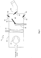
- a device 10 for controlling the thermal comfort in a motor vehicle comprises a vent 12 for the directional outflow of air conditioned in a ventilation, heating or air-conditioning system 14 into an outflow area which extends through the dotted area 16 in FIG Fig. 1 is shown.
- the vent 12 has air guide elements 18, which are adjustable via an adjusting element 20 in order to determine the outflow region 16 and thus the direction of the outflowing air, which is indicated by arrows 22, changeable.
- the exiting from the vent 12 airflow, which has a certain temperature, one in the Fig. 1 and 5 surface 24, which may be a specific body region of a vehicle occupant, for example.
- the device 10 has a temperature sensor 26, which can measure the surface temperature of the surface 24 without contact, the solid angle ⁇ , which the temperature sensor 26 can still detect, being dimensioned such that the measuring surface 28 detected by the temperature sensor 26, which in FIG the Fig. 1 and 5 hatched, which corresponds approximately to the Beeranström preparation given by the orientation of the air guide elements 18 of the Ausströmers 12 or directly from the Ausströmer 12 Heilanström preparation. This area does not have to be circular.
- the temperature sensor is preferably in a thermopile sensor, which can detect the applied by the vent solid angle corresponding to an opening angle between 30 ° and 120 ° without the use of additional optics.
- the air flow 16 flows in this embodiment with an opening angle of this solid angle of z. B. 60 °, or the air flow is aligned with respect to direction and opening angle, so that the detected by the temperature sensor measuring surface 28 corresponds to the Lucasanström nature.
- the outflow 12 has an airflow control element 30, which may be formed, for example, as a throttle valve and can be actuated via an actuating element 32.
- the temperature sensor 26, the actuator 20 and the throttle actuator 32 are connected via corresponding signal and control lines shown in dashed lines with a control unit 34.
- Setpoint values for a specific temperature and / or air guide element position can be input via a signal line 36 via a control unit of the air conditioning system 14, whereupon the control unit 34 controls the actuating element 20 and the throttle valve element 32 accordingly, so that the target desired on the surface 24 Temperature is reached and maintained.
- the actual surface temperature is monitored by the temperature sensor 26 and the throttle valve 30 is driven accordingly to reach the target surface temperature.
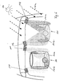
- the device 10 is part of in Fig. 2 schematically illustrated air conditioning system 14 having an air guide housing 40 in which a fan 42 is arranged to promote fresh or recirculated air.
- the air is cooled in a cooling heat exchanger 44, for example, an evaporator of a refrigerant circuit, not shown, and can be passed as cold air to a heating heat exchanger 46 or heated in the heating heat exchanger 46 and supplied to the air mixing chamber 48 as hot air, the ratio between cold and Warm air via a mixing flap 50 is adjustable.
- a defrost air duct 52, a ventilation air duct 54 and a foot air duct 56 branch off.
- the air ducts can be closed by flaps 58, 60, 62. Air can be fed directly to the windshield via the defrost air channel 52.
- the air is guided to at least one device 10 according to the invention, wherein in a dashboard 64, as in the Fig. 3 and 4 is shown, for example, three of the devices 10 according to the invention can be arranged, wherein one is arranged on the left 10.1 and 10.3 right side and a third 10.2 is arranged centrally in the middle.
- This arrangement has the advantage that, for example, in the case of solar radiation from the left, as in Fig. 3 indicated by arrows 66, the left side of the driver arranged device 10.1 can direct a high cooling performance on the left side of the driver.
- the centrally located device 10.2 can also direct high cooling power to the left side of the passenger, and the right side device 10.3 can cool the shaded right side of the passenger with reduced cooling power as needed.
- the lower cooling capacity of the device 10.3 is in Fig. 3 represented by smaller points in the discharge area 16.3.
- control unit may include a recognition and control device, with a temperature gradient on the surface 24 to be tempered in the detected solid angle region 28 can be seen.
- the air guiding elements 18 could be moved by the adjusting element 20 in such a circular manner that the temperature sensor 26 connected to the air guiding elements performs a slightly circular or pivoting movement and thus a temperature gradient on the measured surface 24 can be determined. After determining the temperature gradient of the center of gravity of the circular motion can be moved in the direction of the gradient, so that so that the center of Heilausströmkegels is shifted, for example in the direction of the largest cooling demand.
- a first heat exchanger 70, a cooling heat exchanger and a second heat exchanger 72 may be a heating heat exchanger.
- a control valve 74 the heat transfer medium through the cooling heat exchanger 70 can be controlled and accordingly can be controlled by the heating heat exchanger 72 with a control valve 76, the flow.
- the control valves 74 and 76 are connected via signal lines 78 and 80 to the control unit 34, so that via the control unit 34, the.
- Temperature of the exiting air in the outflow region 16 is adjustable by the control unit 34.
- the air temperature in the vent 12 may additionally be measured and controlled via a temperature sensor 82.
- the heat transfer medium lines for the heating heat exchanger 42 could be saved if this heating heat exchanger 42 electrical heating elements, such as PTC elements contains.
- the control valve 76 would then be replaced by an electrical power regulator.
- the resulting increased power requirements for the vehicle electrical system can be easily implemented if a 42 volt vehicle electrical system is implemented in future vehicles.
- a heating heat exchanger may be provided in the vent 12, so that in the air conditioner 14, the air is cooled only via the cooling heat exchanger 44 and, if necessary, reheated in each outlet 12 to the corresponding desired temperature becomes.
- the conditioned air in the outlet nozzle or in the air conditioner is admixed with untempered air to set a separate temperature for each outlet nozzle.
- the provision of the untempered air could, for example, take place via its own air duct, which leads to each outlet nozzle and is admixed there via a mixing flap of the tempered air.
- the admixing of the untempered air can also via its own small fan in the vents, whereby indoor air is mixed with the provided by the air conditioning in the air duct tempered air in the vents and thus the predetermined by the control unit air temperature is achieved done.
- FIG. 6 shows a schematic representation of two persons 100 and 101 in a motor vehicle.
- the persons nozzles 110, 111, 112 and 113 are arranged, from which air streams flow out.
- the air streams are directed specifically towards the occupants.
- the sun 120 is an influence or source of interference and, due to the lateral radiation 120a, causes a directionally different radiation, which leads to different temperatures of the occupants.
- the occupant 101 has a reinforced area 101a due to the solar radiation, which has an increased surface temperature.
- the area 101b is not so much heated by shadowing. It is comparable with the areas 100a and 100b of the second occupant 100.
- outlets 110 to 113 can specifically let different cold air flow, so that a direct cooling can be done effectively.
- the amount of air that flows out of the respective vents may be different, so that out of the vents with high cooling demand flows out a lot of air.
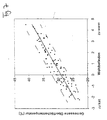
- the FIG. 7 shows a representation of a measured surface temperature of subjects at different body sites as a function of their respective well-being of the respective test persons.
- the respective measurements were carried out in summer clothing. Simultaneously with the recording of the surface temperature on the clothing or on the body, the subjects requested a feel-good indicator in the range of -3 for too cold to +5 for too warm.
- the different persons and the different parts of the body or clothing positions generate a scatter according to this view FIG. 7 ,
- the solid line represents an average or an averaged course, after which at a surface temperature of about 28 ° C to 29 ° C a medium well-being is present. However, this temperature varies with different people in the range of about 26 ° C to about 33 ° C according to the broken lines.
- the curve shifts or move the measuring points to lower temperatures.
- the adaptation of the comfort temperature can be effected for example by at least one actuator or a plurality of actuators, by means of which the surface temperature to be adapted to the well-being due to the clothing situation is adjustable.
- Such an actuator may be, for example, a controller or other adjustment that is adjustable by the occupants.
Description
Die Erfindung betrifft eine Klimaanlage und eine Vorrichtung zur Regelung des thermischen Komforts in einem Kraftfahrzeug gemäß dem Oberbegriff des Anspruchs 1 sowie eine Klimaanlage mit einer solchen Vorrichtung.The invention relates to an air conditioner and a device for controlling the thermal comfort in a motor vehicle according to the preamble of
Die Herstellung eines angenehmen thermischen Klimas in Fahrzeuginnenräumen ist aufgrund der durch Sonneneinstrahlung eingebrachten Wärmelast deutlich schwieriger als in größeren stationären Räumen mit relativ geringer volumenbezogener Wärmelast durch Sonneneinstrahlung. Gründe hierfür sind:
- Fahrzeuginnenräume sind relativ klein und enthalten ein geringes Luftvolumen;
- die solare Wärmelast, also die eingestrahlte Leistung, ist durch die großen und flach stehenden Scheiben sehr groß;
- die Insassen werden teilweise durch die direkte Sonneneinstrahlung in Abhängigkeit der Einstrahlrichtung und etwaiger vorhandener Abschattung lokal unterschiedlich aufgeheizt;
- die Luftausströmer befinden sich in nur geringem Abstand von den Insassen, wodurch große Temperaturunterschiede entstehen;
- die von der Sonne aufgeheizte Fahrzeugumschließungsfläche strahlt Wärme im langwelligen Infrarotbereich an die Fahrzeuginsassen ab. Diese aufgeheizten Einbauten kühlen sich deutlich langsamer ab, als die Innenraumluft. Die Folge ist ein Ungleichgewicht zwischen Luft- und Strahlungstemperatur.
- die manuelle Einstellung der Luftausströmer auf eine bestimmte Sonneneinstrahlung ist schwierig, da sich die Ausrichtung des Fahrzeugs zum Sonnenstand ständig ändert.
- Vehicle interiors are relatively small and contain a small volume of air;
- the solar thermal load, ie the radiated power, is very large due to the large and flat discs;
- The occupants are partially locally heated differently by the direct sunlight as a function of the direction of incidence and any shading present;
- the air vents are located only a short distance from the occupants, resulting in large temperature differences;
- the vehicle-surrounding surface heated by the sun radiates heat in the long-wave infrared range to the vehicle occupants. These heated internals cool much slower than the indoor air. The consequence is an imbalance between air and radiation temperature.
- manual adjustment of the air vents to a particular solar radiation is difficult because the orientation of the vehicle to the position of the sun constantly changes.
Die hohe Wärmelast des durch die dunklen, stark absorbierenden Oberflächen fast wie ein Sonnenkollektor wirkenden Fahrzeuginnenraumes erfordert zur Kompensation eine hohe Kälteleistung, die als Kaltluftstrom in das Fahrzeug eingeblasen wird. Durch den geringen Abstand zwischen Insassen und Luftausströmern können unangenehme Zugeffekte entstehen. Die für einen hohen Komfort erforderlichen geringen Temperaturunterschiede auf der Oberfläche der Fahrzeuginsassen, wie der Kleidung und der Haut, können dadurch kaum erzielt werden.The high heat load of acting through the dark, highly absorbent surfaces almost like a solar panel vehicle interior requires to compensate for a high cooling capacity, which is injected as cold air flow into the vehicle. Due to the small distance between occupants and air vents unpleasant effects can occur. The required for a high level of comfort low temperature differences on the surface of the vehicle occupants, such as the clothing and the skin can be achieved hardly.
Im Winter führen kalte Türen und Fenster zu einem fehlenden Wohlbefinden im Fahrzeug, wobei von einer Seite einfallende Sonnenstrahlung dieses Wohlbefinden wieder herstellen kann. Nach längerer Aufwärmung des Fahrgastinnenraums kann die seitlich einfallende Sonnenstrahlung allerdings auch wieder als unangenehm empfunden werden. Herkömmliche Klimaanlagen reagieren nicht ausreichend auf die unterschiedlichen Zustände, die für den Fahrer u.U. ganz anders sein können, als für den Beifahrer.In winter, cold doors and windows lead to a lack of well-being in the vehicle, whereby from one side incident solar radiation can restore this well-being. After prolonged warming of the passenger compartment, however, the laterally incident solar radiation can again be perceived as unpleasant. Conventional air conditioning systems do not respond sufficiently to the different conditions that may be encountered by the driver. can be very different than for the passenger.
Hinzu kommt noch, daß es in der kurzen zur Verfügung stehenden Zeit einer häufig relativ kurzen Autofahrt (ca. 10 Minuten) kaum möglich ist, einen angenehmen Beharrungszustand im Fahrzeuginnenraum zu erreichen. Sowohl das Fahrzeug selbst, als auch Fahrzeuginsassen sind dadurch ein Großteil der Zeit relativ weit entfernt von einem thermisch ausgeglichenen Zustand, in dem Behaglichkeit entstehen kann.In addition, it is hardly possible in the short time available, often a relatively short drive (about 10 minutes), to achieve a comfortable steady state in the vehicle interior. Both the vehicle itself and the vehicle occupants are relatively far away from a thermally balanced state in which comfort can arise, much of the time.
Ein großer Mangel heutiger Klimaanlagen, die mit einem fest an einer Stelle angeordneten Temperatursensor arbeiten, liegt darin, daß die Zeitdauer bis zum Erreichen eines Komfortzustandes, gemessen an den mittleren Fahrtzeiten, zu lange ist. Diese Sensoren sind in der Regel im Bedienelement der Klimaanlage angeordnet und es erfolgt eine Berechnung der Kopfraumtemperatur. Um den aufgeheizten Fahrzeuginnenraum in möglichst kurzer Zeit auf eine komfortable Temperatur zu kühlen, werden hohe Luftmengen mit sehr niederer Temperatur in den Fahrzeuginnenraum geblasen. Hierbei entstehen sehr große Temperaturdifferenzen auf der Oberfläche der Fahrzeuginsassen. Insbesondere werden die im Austrittskegel der Ausströmer liegenden Körperbereiche zu stark abgekühlt, während andere Körperpartien, die der vollen Sonneneinstrahlung ausgesetzt sind sehr stark aufgeheizt werden. Insbesondere dann, wenn die Insassen schon beim Einstieg leicht verschwitzt sind, können Zugeffekte sogar zu gesundheitlichen Beeinträchtigungen führen.A major shortcoming of today's air conditioning systems, which operate with a temperature sensor fixed in one place, is that the time to reach a comfort state, measured by the average travel times, is too long. These sensors are usually arranged in the control of the air conditioning and there is a calculation of the headspace temperature. In order to cool the heated vehicle interior to a comfortable temperature in the shortest possible time, high amounts of air are blown into the vehicle interior at a very low temperature. This results in very large temperature differences on the surface of the vehicle occupants. In particular, the areas of the body lying in the outlet cone of the outlets are excessively cooled, while other parts of the body which are exposed to full solar radiation are heated very strongly. In particular, when the occupants are slightly sweaty already at the entrance, train effects can even lead to health problems.
Im Falle eines beispielsweise im Winter stark abgekühlten Fahrzeugs wird sehr viel Warmluft in den Innenraum geblasen. Dabei können einzelne Bereiche zu stark aufgewärmt werden, wenn die Sonne lokal einen zusätzlichen Wärmeeintrag leistet.In the case of a vehicle that has cooled down considerably in the winter, for example, a lot of warm air is blown into the interior. In this case, individual areas can be warmed up too much if the sun makes an additional local heat input.
Auch nach Erreichen des stationären Zustandes wird mit einer solchen Klimaanlage mit ausschließlicher Regelung der Lufttemperatur des Fahrzeuginnenraums, nicht der auf die Fahrzeuginsassen einwirkenden Wärmestrom, der von den aufgeheizten Oberflächen, wie Armaturentafel, Scheiben, Sitze, etc., des Innenraums ausgeht, berücksichtigt.Even after reaching the steady state is considered with such an air conditioner with exclusive control of the air temperature of the vehicle interior, not the heat acting on the vehicle occupant heat flow, which emanates from the heated surfaces, such as dashboard, windows, seats, etc., of the interior.
Auch ein zusätzlicher Solarsensor, wie sie heute schon zum Einsatz kommen, berücksichtigt nicht die zeitlich sehr unterschiedliche langwellige Infrarotstrahlung, die von den inneren Oberflächen und Einbauten ausgeht, sowie die Inhomogenitäten durch unterschiedliche Abschattungen und Luftausströmrichtungen der Düsen, die zu Zugeffekten führen können. Darüberhinaus mißt der Solarsensor nur die Störgröße (Sonne), nicht aber die Wirkung der Störgröße und der Umschließungsflächen auf die Insassen des Fahrzeugs.Also, an additional solar sensor, as they are already used, does not take into account the very different long-wave infrared radiation emanating from the inner surfaces and internals, and the inhomogeneities by different shadowing and Luftausströmrichtungen the nozzles, which can lead to train effects. In addition, the solar sensor measures only the disturbance variable (sun), but not the effect of the disturbance variable and the enclosing surfaces on the occupants of the vehicle.
Das beste Signal zur lokalen Messung und Charakterisierung eines Komfortzustandes liefert ein Oberflächentemperatur-Meßsensor (z.B. Thermopile-Sensor), der die Wirkung aller thermisch relevanten Größen berücksichtigt, also eine sogenannte Klima-Summengröße liefert. Der Einsatz eines solchen Sensors in der Regelung für eine Fahrzeugklimaanlage ist beispielsweise aus der
Ferner beschreibt die
Ausgehend von diesem Stand der Technik ist es Aufgabe der Erfindung, eine verbesserte Klimaanlage bzw. eine Vorrichtung zur Regelung des thermischen Komforts bereitzustellen, mit der die vorgenannten Nachteile vermeiden werden können und mit der möglichst alle für den Klimakomfort relevanten Einflußgrößen berücksichtigt werden können. Insbesondere sollen thermische Inhomogenitäten, die durch die zeitlich und örtlich ständig variierenden Strahlungsverteilungen auf der Oberfläche der Insassen, wie sie durch wechselnde Einstrahlrichtungen und Abschattungen der Sonne durch Fahrtrichtungsänderungen, Wolken, Baumreihen und Tunnelfahrten etc., entstehen können, erkannt und kompensiert werden. Auch sollen Zugeffekte, beispielsweise durch lokal starke Abkühlungen durch zu kalte Luft, vermieden werden.Based on this prior art, it is an object of the invention to provide an improved air conditioning system or a device for controlling the thermal comfort, with which the aforementioned disadvantages can be avoided and with all possible influencing variables relevant for the climate comfort can be considered. In particular, thermal inhomogeneities caused by the temporally and spatially constantly varying radiation distributions on the surface of the occupants, as may occur due to changing irradiation directions and shadowing of the sun due to changes in direction, clouds, rows of trees and tunnel drives, etc., should be detected and compensated. Also, train effects, for example by locally strong cooling by too cold air, should be avoided.
Weitere Aufgabe der Erfindung ist es, die benötigte Kälteleistung zur Erzielung eines verbesserten Komforts zu minimieren und Kraftstoff einzusparen.Another object of the invention is to minimize the required cooling capacity to achieve improved comfort and to save fuel.
Diese Aufgabe wird gelöst durch eine Klimaanlage mit den Merkmalen des Anspruchs 1.This object is achieved by an air conditioner with the features of
Vorteilhaft ist die Schaffung einzelner insassenbezogener Mikroklimazonen und die Regelung der Lufttemperatur und/oder der Luftmenge in jeder Kimazone gegebenenfalls getrennt.Advantageously, the creation of individual occupant microclimate zones and the regulation of the air temperature and / or the amount of air in each Kimazone optionally separate.
Die Vorrichtung zur Regelung des thermischen Komforts weist zum einen wenigstens einen eine sich räumlich erstreckende Meßfläche erfassenden Temperatursensor und einen Ausströmer zur gerichteten Ausströmung von in einer Klimaanlage temperierter Luft in einen Ausströmbereich auf, wobei erfindungsgemäß die von dem Temperatursensor erfasste Meßfläche der von der durch die Ausrichtung des Ausströmers vorgegebenen Luftanströmfläche in etwa entspricht.The device for controlling the thermal comfort has on the one hand at least one of a spatially extending measuring surface detecting Temperature sensor and an outflow for the directional outflow of air conditioned in an air conditioner in an outflow region, wherein according to the invention the detected by the temperature sensor measuring surface of the predetermined by the orientation of the Ausströmers Luftanströmfläche corresponds approximately.
Dadurch ist gewährleistet, daß unabhängig von der Ausrichtung des Ausströmers immer die Temperatur der Oberfläche gemessen wird, die für das thermische Empfinden relevant ist und daher auch temperiert werden soll. Dadurch können die vorgenannten Nachteile vermieden und der Komfort und das Wohlfühlbefinden der Insassen erhöht werden.This ensures that, regardless of the orientation of the outflow always the temperature of the surface is measured, which is relevant to the thermal sensation and therefore should also be tempered. As a result, the aforementioned disadvantages can be avoided and the comfort and well-being of the occupants can be increased.
Die vom Sensor erfaßte Oberflächentemperatur wird als resultierende Oberflächentemperatur bezeichnet und enthält alle komfortrelevanten Größen wie
- Lufttemperatur
- Konvektiver Wärmeübergang der angeblasenen Oberfläche
- Abkühlung feuchter Oberflächen durch Verdunstung
- Farbe
- Absorptionskoeffizient der Kleidung
- Strahlungstemperatur der Umschließungsfläche (langwellige IR-Strahlung),
- Sonneneinstrahlung (kurzwelliges Strahlungsspektrum),
- air temperature
- Convective heat transfer of the blown surface
- Cooling of damp surfaces by evaporation
- colour
- Absorption coefficient of clothing
- Radiation temperature of the enclosure surface (long-wave IR radiation),
- Solar radiation (short-wave radiation spectrum),
Damit wird die Temperierung des erfassten Bereiches inklusive aller äußerer Einflüsse, wie Sonneneinstrahlung, Abschattungen etc. ermöglicht, und es wird stets die korrekte komfortrelevante Oberflächentemperatur erreicht.Thus, the temperature of the detected area including all external influences, such as solar radiation, shadowing, etc. is enabled, and it is always the correct comfort relevant surface temperature achieved.
Durch die direkte Messung der Oberflächentemperatur läßt sich eine direkte Klimatisierung der Insassen mit dezenten diffusen oder direkten eher strahlförmigen Luftströmungen durchführen, da eine Änderung der Bedingungen, wie beispielsweise wechselnde Sonneneinstrahlungen, ein Abdriften, wie Absinken oder Erhöhen, der Komfortoberflächentemperatur sofort erfaßt wird und regelungstechnisch eingegriffen werden kann. Diese direkte Klimatisierung kann sowohl strahlförmig also mit hoher Strömungsgeschwindigkeit erfolgen als auch dezent diffus. Mit diffuser Strömung ist gemeint, daß Luft aus den Ausblasdüsen großen Querschnitts mit geringen Geschwindigkeiten austritt oder aber die Luft in den Austrittsdüsen divergierend bzw. aufgefächert austritt und beim Einströmen in Fahrgastraum sehr viel seiner kinetischen Energie verliert.By directly measuring the surface temperature, a direct air conditioning of the occupants can be carried out with subtle diffuse or direct rather jet-shaped air currents, since a change in conditions, such as changing solar radiation, drifting, such as lowering or increasing, the comfort surface temperature is detected immediately and intervened control technology can be. This direct air conditioning can be both jet-shaped so with high flow rate as well as subtly diffuse. By diffused flow is meant that air exits the discharge nozzles large cross-section at low speeds or the air in the outlet nozzles divergent or fanned out and loses much of its kinetic energy when flowing into the passenger compartment.
Dabei wird die Fahrgastluft dezent verdrängt bzw. Luft der Fahrgastzelle in den diffusen Luftstrom eingemischt.The passenger air is discreetly displaced or the air of the passenger compartment is mixed into the diffuse air flow.
Vorzugsweise wird die direkte Klimatisierung über diffuse Ausströmer bewerkstelligt.Preferably, the direct air conditioning is accomplished via diffuse vents.
Darüberhinaus ist die gemessene Oberflächentemperatur mindestens einer Klimazone heranzuziehen, um die Art der Luftausströmung in zumindest einer Klimazone von strahlförmig auf diffus umzustellen. Im Bereich großen Diskomforts ist eine direkte strahlförmige Klimatisierung sinnvoll, während nahe am Komfortzustand eher eine diffuse Klimatisierung als angenehm empfunden wird.In addition, the measured surface temperature of at least one climate zone is used to change the type of air outflow in at least one climate zone from jet to diffuse. In the area of large disasters, a direct jet-shaped air conditioning makes sense, while close to the comfort state rather a diffuse air conditioning is perceived as pleasant.
Durch diese direkte Klimatisierung der Insassen, bei der die Insassen direkt mit der temperierten Luft abgeströmt werden, kann Heiz- bzw. Kühlleistung eingespart werden, da nicht der gesamte Fahrgastraum inkusive aller Einbaumassen auf eine komfortable Temperatur geheizt bzw. heruntergekühlt werden muß, sondern die Körperobertläche der Insassen durch direkte aber moderate Anblasung mit geeignet temperierter Luft so konditioniert wird, daß zumindest annähernd ein hoher Komfortzustand erzielt wird, indem der Insasse von der temperierten Luft umhüllt wird.By this direct air conditioning of the occupants, in which the occupants are directly flowed away with the tempered air, heating or cooling power can be saved because not the entire passenger compartment including all mounting dimensions must be heated or cooled down to a comfortable temperature, but the Körperobertläche the occupant is conditioned by direct but moderate blowing with suitably tempered air so that at least approximately a high comfort state is achieved by the occupant is enveloped by the tempered air.
Ein weiterer Vorteil ist ebenfalls, daß durch die direkte Klimatisierung jeder Mikroklimazone die direkte Wirkung der ausgeblasenen Luft auf das gemessene Oberflächentemperatursignal schnell erfaßt wird. Damit können besonders schnell wechselnde Bedingungen in sehr kurzer Zeit ausgeregelt werden können.Another advantage is also that the direct air conditioning of each micro-climate zone quickly detects the direct effect of the blown air on the measured surface temperature signal. This allows very fast changing conditions can be corrected in a very short time.
Vorzugsweise liegen der Temperatursensor und der Luftausströmer sehr nahe beieinander oder bilden sogar eine bauliche Einheit. Die Erfassungsrichtung des Temperatursensors und die Ausströmrichtung des Ausströmers sind dann gleichzeitig verstellbar und immer exakt aufeinander abgestimmt.Preferably, the temperature sensor and the air vent are very close to each other or even form a structural unit. The detection direction of the temperature sensor and the outflow of the outflow are then simultaneously adjustable and always exactly matched.
In einer konstruktiv vorteilhaften Ausgestaltung der Erfindung weist der Ausströmer Luftleitelemente zur Strömungrichtungsgebung auf, wobei der die Oberflächentemperatur berührungslos messende Sensor an wenigstens einem der Luftleitelemente befestigt ist. Dadurch ist in einfachster Weise gewährleistet, daß dieser berührungslos messende Temperatursensor und der Ausströmer auf dieselbe Fläche ausgerichtet sind.In a structurally advantageous embodiment of the invention, the vent on air guide elements for flow direction, wherein the surface temperature of the non-contact measuring sensor on at least one the spoiler elements is attached. This ensures in the simplest way that this non-contact measuring temperature sensor and the vent are aligned on the same surface.
In Weiterbildung der Erfindung besteht der berührungslos messende Temperatursensor aus einem Thermopileelement.In a development of the invention, the non-contact measuring temperature sensor consists of a thermopile element.
Wenn der Luftstrom beispielsweise in etwa kegelförmig austritt und der Temperatursensor den Raumwinkel, der in etwa dem Öffnungswinkel des Luftaustrittskegels entspricht, erfasst, kann insbesondere der Ausströmer einfach aufgebaut sein, wobei der Öffnungswinkel des Sensors oder der von ihm direkt temperierbaren Fläche 30° bis 120°, bevorzugt etwa 60° beträgt, so daß auf eine kostenintensive Optik verzichtet werden kann und der Durchmesser des vom Sensor erfassten Bereichs etwa dem Durchmesser der belüfteten Fläche und gleich dem Abstand des angeströmten Objekts zum Ausströmer entspricht. In weiterer Ausgestaltung der Erfindung kann der vom Ausströmer beaufschlagte und vom Temperatursensor erfasste Raumwinkelbereich auch nicht rotationssymmetrisch sondern z. B. oval sein, um den gesamten zu temperierenden Oberflächenbereich eines Fahrzeuginsassen besser abzubilden.For example, if the airflow emerges approximately conically and the temperature sensor detects the solid angle, which approximately corresponds to the opening angle of the air outlet cone, then the outflow may be simple, with the opening angle of the sensor or of the surface directly controllable by it being 30 ° to 120 ° , Preferably about 60 °, so that can be dispensed with a costly optics and the diameter of the area detected by the sensor corresponds approximately to the diameter of the ventilated area and equal to the distance of the object flown to the vent. In a further embodiment of the invention, the acted upon by the vent and detected by the temperature sensor solid angle range is not rotationally symmetrical but z. B. be oval in order to better reflect the entire surface area of a vehicle occupant to be tempered.
Mittels Thermopilesensoren oder anderen ähnlich arbeitenden Sensoren lassen sich die Luftmengen und/oder die Lufttemperaturen an den einzelnen Ausblasdüsen dahingehend regeln, daß die erzielten Oberflächentemperaturen in den einzelnen Mikroklimazonen in einen komfortablen Bereich überführt werden können. Dies kann beispielsweise dadurch erfolgen, daß die Luftmenge und/oder Lufttemperatur an der Mitteldüse und an der Seitendüse im wesentlichen jedes Insassen oder im wesentlichen jeder Sitzposition in gleicher Weise geregelt wird oder aber Seiten- und Mitteldüsen jeder Sitzposition oder jedes Insassen unterschiedlich temperierte Luft und/oder unterschiedliche Luftmenge ausbläst, um der Richtung der Störung, wie beispielsweise einer Sonneneinstrahlung, gerecht zu werden und diese auszugleichen.By means of thermopile sensors or other similarly operating sensors, the amounts of air and / or the air temperatures at the individual exhaust nozzles can be regulated so that the surface temperatures achieved in the individual microclimate zones can be converted into a comfortable range. This can be done, for example, that the air flow and / or air temperature at the center nozzle and the side nozzle substantially every occupant or substantially every seat position is regulated in the same way or side and center nozzles of each seat position or each occupant differently tempered air and / or blows out different amounts of air to cope with and compensate for the direction of the disturbance, such as solar radiation.
Vorteilhaft ist es, wen jedem Insassen oder jeder Sitzposition zumindest ein Sensor, wie Thermopilesensor, zugeordnet ist, der vorzugsweise in den Ausblasdüsen oder in der Nähe der Ausblasdüsen angeordnet ist. Er kann je nach Ausführungsbeispiel auch an anderer Stelle, wie in einer A-Säule, im Bedienelement, auf dem Armaturenbrett oder im Dachhimmel, plaziert werden.It is advantageous to whom each occupant or each seating position at least one sensor, such as thermopile sensor, is assigned, which is preferably arranged in the exhaust nozzles or in the vicinity of the exhaust nozzles. Depending on the embodiment, it can also be placed elsewhere, such as in an A-pillar, in the operating element, on the dashboard or in the headliner.
Auch kann es vorteilhaft sein, wenn nicht jede Mikroklimazone von einem eigenen Sensor überwacht wird. Es kann auch eine Berechnung der Temperaturen in Mikroklimazonen mittels Temperatursensoren oder Thermoelementen, die anderen Klimazonen zugeordnet sind, erfolgen. Für die Fondbelüftung könnte vorzugsweise die Signale von Sensoren der vorderen Sitzpositionen oder Insassen verwendet werden.It may also be advantageous if not every micro-climate zone is monitored by its own sensor. It is also possible to calculate the temperatures in microclimate zones by means of temperature sensors or thermocouples, which are assigned to other climatic zones. For the rear ventilation, the signals from sensors of the front seat positions or occupants could preferably be used.
Erfindungsgemäß könnten auch weitere Düsen in A- Säule, B-Säule oder C-Säule, Dachhimmel, Armaturenbrett sowie in den Türen zur direkten Temperierung der Mikroklimazonen herangezogen werden. Dabei müssen nicht alle Ausströmer auf die Insassen oder Sitzpositionen gerichtet sein. Vorzugsweise wird aber jede Sitzposition oder jeder Insasse zu zumindest von einem Ausströmer direkt mit Luft klimatisiert, die vorzugsweise mittels eines Sensors, eines Thermopilesensors, geregelt wird. Die direkte Klimatisierung der Mikroklimazonen strahlförmig, diffus oder mit aufgefächertem Luftstrom erfolgen. Vorzugsweise erfolgt die direkte Klimatisierung diffus, kann aber auch so gestaltet sein, daß bei großer Abweichung von der Soll-Oberflächentemperatur die Klimatisierung zunächst strahlförmig und dann bei Erreichen des Komfortzustands diffus erfolgt.According to the invention, other nozzles in A-pillar, B-pillar or C-pillar, headliner, dashboard and in the doors for direct temperature control of microclimatic zones could be used. Not all of the vents must be aimed at the occupants or seating positions. Preferably, however, each seat position or each occupant is air-conditioned directly to at least one air vent, which is preferably regulated by means of a sensor, a thermopile sensor. The direct air conditioning of the microclimate zones jet-shaped, diffused or carried out with fanned air flow. Preferably, the direct air conditioning is diffuse, but can also be designed so that at large deviation from the target surface temperature, the air conditioning is first jet-shaped and then diffusely on reaching the comfort state.
Das Sensorsignal, das ein Maß für die Temperatur des von dem Ausströmer angeblasenen Objektbereichs, vorzugsweise eines Teilbereichs eines Insassen darstellt, wird in Weiterbildung der Erfindung einer Regeleinheit zugeführt, die auf ein Steuerelement zur Variation der vom Ausströmer ausgeblasenen Luftmenge und/oder Lufttemperatur so einwirkt, daß die vom Ausströmer erreichten Objektoberflächenbereiche auf einem komfortablen Wert gehalten werden.The sensor signal, which is a measure of the temperature of the object area blown by the vent, preferably a portion of an occupant, is fed in a development of the invention to a control unit which acts on a control element for varying the amount of air and / or air temperature blown out by the vent, that the object surface areas reached by the vent are maintained at a comfortable level.
Je nach Kleidungsdicke variiert die komfortabel erachtete Oberflächentemperatur. Im Sommer bei warmen Temperaturen wird aufgrund der leichten Bekleidung eine Oberflächentemperatur im Bereich von ca. 26°C und ca. 31°C als angenehm empfunden, während im Winter durch eine dickere Bekleidung die komfortable Oberflächentemperatur geringer ist, wie zum Beispiel im Bereich von 18°C bis 26°C.Depending on the clothing thickness, the comfortable surface temperature varies. In summer, when the temperature is warm, a surface temperature in the range of about 26 ° C and about 31 ° C is perceived as pleasant due to the light clothing, while in winter through a thicker clothing, the comfortable surface temperature is lower, such as in the range of 18 ° C to 26 ° C.
Zu kalte oder zu heiße Luftströme, die als unangenehm empfunden werden könnten, werden vermieden. Störgrößen durch sich u. U. schnell ändernde Strahlungsverhältnisse werden sofort kompensiert.Too cold or too hot air currents that could be perceived as unpleasant, are avoided. Disturbances by u. U. rapidly changing radiation conditions are compensated immediately.
Damit ist der Vorrichtung eine gewisse "Eigenintelligenz gegeben, so daß entsprechend von einem Insassen vorgegebenen Temperaturvorgaben die Vorrichtung selbsttätig die gewünschte Temperatur am gewünschten Ort einstellt.Thus, the device is given a certain "Eigenintelligenz, so that according to predetermined by an occupant temperature specifications, the device automatically adjusts the desired temperature at the desired location.
Das Steuerelement kann in einfacher Ausführung eine im Klimagerät oder in dem Ausströmer angeordnete Drosselklappe, mit der die Luftmenge regelbar ist, sein. In weiterer Ausgestaltung der Erfindung kann das Steuerelement ein oder mehrere Regelventile umfassen, mit dem beispielsweise der Durchfluss durch wenigstens einen in dem Ausströmer angeordneten Wärmetauscher regelbar ist. Dann wäre es möglich, die Luft erst in dem Ausströmer, entsprechend vorgegebenen Temperafureinstellungen und den Signalen des Temperatursensors zu temperieren.The control can be in a simple embodiment arranged in the air conditioner or in the vent throttle, with which the amount of air is adjustable, be. In a further embodiment of the invention, the control may comprise one or more control valves, with which, for example, the flow through at least one arranged in the vent heat exchanger can be controlled. Then it would be possible to temper the air only in the vent, according to predetermined temperaure settings and the signals of the temperature sensor.
Damit ist ein "intelligenter" Ausströmer geschaffen, dem lediglich vorgegeben wird, welche Temperatur in welchem Bereich erreicht werden soll und der die weitere Temperaturregelung unabhängig von weiteren äußeren Einflüssen selbsttätig durchführt.Thus, an "intelligent" vent is created, which is merely specified, which temperature is to be achieved in which area and automatically carries out the further temperature control independently of other external influences.
Der Wärmetauscher könnte auch lediglich oder zusätzlich elektrische Heizelemente, wie PTC-Elemente oder andere resistive Heizelemente, aufweisen, wodurch Leitungen für ein Wärmeträgermedium in kostengünstiger Weise entfallen. Das Steuerelement wäre ein elektrischer Regler, mit dem die elektrische Leistung der Heizelemente regelbar ist.The heat exchanger could also only or additionally comprise electrical heating elements, such as PTC elements or other resistive heating elements, whereby lines for a heat transfer medium in cost-effective Way omitted. The control would be an electrical regulator with which the electrical power of the heating elements can be regulated.
In einer weiteren Ausführungsvariante könnte die richtige Lufttemperatur durch Mischung zweier unterschiedlich temperierter Luftströme direkt im Ausströmer oder in einem zentralen Klimagerät erfolgen.In a further embodiment, the correct air temperature could be achieved by mixing two differently tempered air streams directly in the vent or in a central air conditioner.
In einer Ausgestaltung der Erfindung weist die Vorrichtung eine Erkennungsund Steuervorrichtung auf, mit der ein Temperaturgradient in dem erfassten Raumwinkelbereich erkennbar ist. Über einen Stellantrieb für den Ausströmer zur selbsttätigen Verstellung der Luftausströmrichtung in Richtung größter Regelabweichung kann die Ausströmrichtung nachgefahren werden und beispielsweise ein Teilbereich genauer mit der temperierten Luft angeströmt werden.In one embodiment of the invention, the device has a recognition and control device with which a temperature gradient in the detected solid angle range can be seen. About an actuator for the vent for automatic adjustment of the air outflow in the direction of maximum control deviation, the outflow direction can be traced and, for example, a partial area to be more accurately flowed with the tempered air.
Diese Erkennungsvorrichtung kann darin bestehen, dass der die angeblasene Oberfläche berührungslos messende Temperatursensor in mindestens zwei Segmente unterteilt ist und durch Vergleich der beiden Signale einen Temperaturgradienten errechnet. Weiterhin kann diese Erkennungsvorrichtung darin bestehen, daß der Ausströmer zusammen mit dem berührungslos messenden Temperatursensor langsame leicht kreisende oder schwenkende Bewegungen ausführt, um den erreichbaren Oberflächenbereich quasi abzurastern und den Bereich der größten Regelabweichung zu finden.This recognition device may consist in that the temperature sensor which measures the blown-on surface without contact is subdivided into at least two segments and calculates a temperature gradient by comparing the two signals. Furthermore, this detection device can consist in that the outflow together with the non-contact temperature sensor performs slow, gentle circular or pivoting movements to virtually scrape the achievable surface area and to find the area of the largest deviation.
Damit könnte beispielsweise der Einfluß vertikal und/oder horizontal variabler Sonnenstände kompensiert werden. Beispielsweise besteht bei sehr hohen Sonnenständen, z.B. mittags im Sommer, der durch die Sonneneinstrahlung bewirkte größte Kühlbedarf im Bereich des Unterbauchs und der Oberschenkel, während der Brust- und Kopfbereich meist im Schatten liegen. Die Erkennungs- und Steuervorrichtung würde die Ausblasrichtung durch Messung der Regelabweichung automatisch in diese Richtung ausrichten und dort mit gekühlter Luft die durch Strahlungsabsorption entstehende Wärme abführen. Bei flacheren Sonnenständen wandert die besonnte Zone immer weiter nach oben, was von der Erkennungs- und Steuervorrichtung erkannt wird und den Ausströmer nachführt.Thus, for example, the influence of vertically and / or horizontally variable positions of the sun could be compensated. For example, at very high levels of sunlight, for example, noon in the summer, caused by the sunlight largest cooling demand in the area of the lower abdomen and the thigh, while the chest and head area are usually in the shade. The detection and control device would automatically align the discharge direction by measuring the control deviation in this direction and there dissipate the heat produced by radiation absorption with cooled air. In shallower sunsets, the sunnished zone continues to move upwards, which is recognized by the detection and control device and tracks the vent.
Vorteilhafterweise kann die Erkennungs- und Steuervorrichtung auch die Leistung des Wärmetauschers steuern.Advantageously, the recognition and control device can also control the performance of the heat exchanger.
Die beschriebene Vorrichtung kann Teil einer Klimaanlage eines Kraftfahrzeugs sein. Dabei ist es vorteilhaft, wenn einem Fahrzeuginsassen wenigstens zwei Vorrichtungen zugeordnet sind, die in horizontaler Ebene links und rechts vor dem Insassen angeordnet sind, wodurch z.B. Inhomogenitäten der Temperaturverteilung auf der Oberfläche des jeweiligen Insassen, beispielsweise durch wechselnde Sonneneinstrahlung, verringerbar sind. Weiterhin könnte eine Vorrichtung auch dem meist im Schatten befindlichen Fußraumbereich zugeordnet sein, so daß die Vorrichtung, beispielsweise im Winter, die starke Wärmeabstrahlung an die sehr kalten Umschließungsflächen erkennt und kompensiert.The device described may be part of an air conditioning system of a motor vehicle. It is advantageous if at least two devices are associated with a vehicle occupant, which are arranged in the horizontal plane left and right in front of the occupant, whereby Inhomogeneities of the temperature distribution on the surface of the respective occupant, for example by changing solar radiation, can be reduced. Furthermore, a device could also be assigned to the footwell area, which is usually in the shade, so that the device, for example in winter, detects and compensates for the strong heat radiation to the very cold enclosure surfaces.
Insgesamt erfolgt mit der erfindungsgemäßen Vorrichtung ein schneller Ausgleich von örtlichen und zeitlichen Inhomogenitäten der resultierenden Oberflächentemperaturen. Durch den wesentlich direkteren und damit schnelleren Regelkreis von berührungsloser Messung einer von temperierter Luft angeblasenen Oberfläche kann sehr schnell auf wechselnde Besonnungen und Beschattungen reagiert werden. Dabei wird die Hauptstörgröße in idealer Weise kompensiert. Dadurch, daß nicht mehr der gesamte Innenraum inklusive aller Massen heruntergekühlt oder aufgeheizt werden muß, wird der Komfortzustand auch wesentlich schneller erreicht. Weiterhin ist die zur Erzielung eines gewissen Komfortzustandes der Fahrzeuginsassen benötigte Heiz- bzw. Kühlleistung geringer. Vor allem im Sommerfall kann dadurch der für die Klimatisierung benötigte Primärenergieverbrauch reduziert werden.Overall, with the device according to the invention a rapid compensation of local and temporal inhomogeneities of the resulting surface temperatures. Due to the much more direct and thus faster control loop of non-contact measurement of a surface tempered by tempered air, it is possible to respond very quickly to changing tanning and shading. The main disturbance variable is compensated in an ideal way. The fact that no longer the entire interior, including all masses must be cooled down or heated, the comfort state is also achieved much faster. Furthermore, the heating or cooling power required to achieve a certain comfort condition of the vehicle occupants is lower. Especially in the summer, this can be used to reduce the primary energy consumption required for air conditioning.
Durch die Verwendung der erfindungsgemäßen Vorrichtung ließe sich eine Standardisierung der Einzelmodule fahrzeugübergeifend realisieren, die sich nur durch z.B. aufklipsbare fahrzeugspezifische Designelemente unterscheiden. Das würde zu reduzierten Kosten führen.By using the device according to the invention, it would be possible to realize a standardization of the individual modules over the vehicle, which can only be achieved by e.g. distinguish clip-on vehicle-specific design elements. That would lead to reduced costs.
Vorteilhafte Weiterbildungen sind in den Unteransprüchen wiedergegeben.Advantageous developments are given in the dependent claims.
Im Folgenden wird die Erfindung anhand von Ausführungsbeispielen unter Bezugnahme auf die Zeichnung im Einzelnen erläutert. In der Zeichnung zeigen:
- Fig. 1
- eine erste Ausführungsform einer erfindungsgemäßen Vorrichtung zur Regelung des thermischen Komforts;
- Fig. 2
- eine Klimaanlage, bei der die erfindungsgemäße Vorrichtung aus
Fig. 1 einsetzbar ist; - Fig. 3 u. 4
- schematische Darstellungen der Wirkungsweisen von in einer Armaturentafel angeordneten, erfindungsgemäßen Vorrichtungen bei seitlichem Sonneneinfall;
- Fig. 5
- eine weitere Ausführungsform der erfindungsgemäßen Vorrichtung,
- Fig. 6
- eine schematische Darstellung und
- Fig. 7
- eine Darstellung der gemessenen Oberflächentemperatur als Funktion eines ermittelten Wohlbefindens.
- Fig. 1
- a first embodiment of a device according to the invention for controlling the thermal comfort;
- Fig. 2
- an air conditioner in which the device according to the invention
Fig. 1 can be used; - Fig. 3 u. 4
- schematic representations of the effects of arranged in a dashboard, devices according to the invention in lateral sunlight;
- Fig. 5
- a further embodiment of the device according to the invention,
- Fig. 6
- a schematic representation and
- Fig. 7
- a representation of the measured surface temperature as a function of a determined well-being.
Eine erfindungsgemäße Vorrichtung 10 zur Regelung des thermischen Komforts in einem Kraftfahrzeug umfaßt einen Ausströmer 12 zur gerichteten Ausströmung von in einer Belüftungs-, Heizungs- oder Klimaanlage 14 konditionierten Luft in einen Ausströmbereich, der durch die gepunktete Fläche 16 in
Weiter weist die erfindungsgemäße Vorrichtung 10 einen Temperatursensor 26 auf, der berührungslos die Oberflächentemperatur der Oberfläche 24 messen kann, wobei der Raumwinkel α, den der Temperatursensor 26 noch erfassen kann, derart bemessen ist, daß die von dem Temperatursensor 26 erfasste Meßfläche 28, die in den
Der Temperatursensor besteht bevorzugt in einem Thermopile-Sensor, der ohne den Einsatz zusätzlicher Optik in etwa den vom Ausströmer beaufschlagten Raumwinkel entsprechend einem Öffnungswinkel zwischen 30° und 120° erfassen kann. Der Luftstrom 16 strömt in diesem Ausführungsbeispiel mit einem Öffnungswinkel, der diesem Raumwinkel von z. B. 60° entspricht, oder der Luftstrom ist hinsichtlich Richtung und Öffnungswinkel ausgerichtet, so daß die von dem Temperatursensor erfasste Meßfläche 28 der Luftanströmfläche entspricht.The temperature sensor is preferably in a thermopile sensor, which can detect the applied by the vent solid angle corresponding to an opening angle between 30 ° and 120 ° without the use of additional optics. The
Des weiteren weist der Ausströmer 12 ein Luftstromsteuerelement 30 auf, das beispielsweise als Drosselklappe ausgebildet sein kann und über ein Stellelement 32 betätigbar ist.Furthermore, the
Der Temperatursensor 26, das Stellelement 20 und das Drosselklappenstellelement 32 sind über entsprechende, gestrichelt dargestellte Signal und Steuerleitungen mit einer Regeleinheit 34 verbunden. Über ein nicht näher dargestelltes Bediengerät der Klimaanlage 14 können über eine Signalleitung 36 Sollwerte für eine bestimmte Temperatur- und/oder Luftleitelementenstellung eingegeben werden, woraufhin die Regeleinheit 34 das Stellelement 20 und das Drosselklappenstellelement 32 entsprechend ansteuert, so daß die auf der Oberfläche 24 gewünschte Soll-Temperatur erreicht und gehalten wird. Dabei wird die Ist-Oberflächentemperatur von dem Temperatursensor 26 überwacht und die Drosselklappe 30 entsprechend angesteuert um die Soll-Oberflächentemperatur zu erreichen.The
Die erfindungsgemäße Vorrichtung 10 ist Teil der in
Über den Belüftungsluftkanal 54 wird die Luft zu wenigstens einer erfindungsgemäßen Vorrichtung 10 geführt, wobei in einer Armaturentafel 64, wie sie in den
Bei Sonneneinfall von rechts, wie dies in
Insgesamt ist damit für den Fahrer und Beifahrer bei wechselndem Sonneneinfall ein höherer Komfort gegeben.Overall, a higher comfort is thus given for the driver and passenger in changing sunshine.
In Weiterbildung der Erfindung kann die Regeleinheit eine Erkennungs- und Steuervorrichtung enthalten, mit der ein Temperaturgradient auf der zu temperierenden Oberfläche 24 in dem erfassten Raumwinkelbereich 28 erkennbar ist. Dazu könnten beispielsweise die Luftleitelemente 18 von dem Stellelement 20 derart kreisförmig bewegt werden, daß der mit den Luftleitelementen verbundene Temperatursensor 26 eine leicht kreisende oder schwenkende Bewegung ausführt und so ein Temperaturgradient auf der gemessenen Oberfläche 24 ermittelbar ist. Nach Ermittlung des Temperaturgradienten kann der Schwerpunkt der Kreisbewegung in Richtung des Gradienten verschoben werden, so daß damit das Zentrum des Luftausströmkegels beispielsweise in Richtung des größten Kühlbedarfs verschoben wird.In a further development of the invention, the control unit may include a recognition and control device, with a temperature gradient on the
In einer weiteren Ausführungsform der erfindungsgemäßen Vorrichtung 10, sind in dem Ausströmer 12, wie in
Bei Einsatz einer derartigen erfindungsgemäßen Vorrichtung 10 sind prinzipiell die Heiz- und Kühlwärmetauscher 44 und 46 in dem Luftführungsgehäuse 40 nicht mehr notwendig, da die Temperierung der Luft am Ende der entsprechenden Luftkanäle jeweils in den einzelnen Ausströmern 12 vorgenommen wird. Dadurch ergibt sich eine erhebliche Bauraumgewinnung im Bereich der zentralen Klimaanlage 14.When using such a
Die Wärmeträgermediumleitungen für den Heizwärmetauscher 42 könnten eingespart werden, wenn dieser Heizwärmetauscher 42 elektrische Heizelemente, wie beispielsweise PTC-Elemente, enthält. Das Regelventil 76 würde dann durch einen elektrischen Leistungsregler ersetzt. Die dadurch erhöhten Leistungsanforderungen an das Fahrzeug-Bordnetz sind problemlos realisierbar, wenn in zukünftigen Fahrzeuge ein 42 Volt Bordnetz realisiert wird.The heat transfer medium lines for the
In einer weiteren nicht dargestellten Ausführungsform der erfindungsgemäßen Vorrichtung 10 ist in dem Ausströmer 12 lediglich ein Heizwärmetauscher vorgesehen sein, so daß in der Klimaanlage 14 die Luft über den Kühlwärmetauscher 44 nur abgekühlt wird und bedarfsweise in jedem einzelnen Ausströmer 12 auf die entsprechende gewünschte Temperatur wieder aufgeheizt wird. Damit ist in einfacher Weise ein dezentrales Klimatisierungskonzept geschaffen, bei dem den einzelnene Ausströmern zugeordnete Fahrzeginnenraumbereiche unterschiedlich temperierbar sind, wodurch der Komfort für die Insassen weiter erhöht ist, denn jeder Insasse kann seine individuelle Temperatur einstellen.In a further embodiment, not shown, of the
In einer weiteren nicht dargestellten Ausführungsform wird der klimatisierten Luft in der Austrittsdüse oder im Klimagerät untemperierte Luft beigemischt, um für jede Austrittsdüse eine eigene Temperatur einzustellen. Die Bereitstellung der untemperierten Luft könnte beispielsweise über einen eigenen Luftkanal erfolgen, der zu jeder Ausblasdüse führt und dort über eine Mischklappe der temperierten Luft zugemischt wird. Die Zumischung der untemperierten Luft kann aber auch über ein eigenes kleines Gebläse in den Ausströmern, wodurch Innenraumluft mit der von der Klimaanlage im Luftkanal bereitgestellten temperierten Luft in den Ausströmern vermischt wird und damit die von der Regeleinheit vorgegebene Lufttemperatur erreicht wird, erfolgen.In a further embodiment, not shown, the conditioned air in the outlet nozzle or in the air conditioner is admixed with untempered air to set a separate temperature for each outlet nozzle. The provision of the untempered air could, for example, take place via its own air duct, which leads to each outlet nozzle and is admixed there via a mixing flap of the tempered air. But the admixing of the untempered air can also via its own small fan in the vents, whereby indoor air is mixed with the provided by the air conditioning in the air duct tempered air in the vents and thus the predetermined by the control unit air temperature is achieved done.
Die
Die Sonne 120 stellt eine Einfluß oder Störquelle dar und verursacht aufgrund der seitlichen Strahlung 120a eine richtungsabhängig unterschiedliche Strahlung, die zu unterschiedlichen Temperierungen der Insassen führt. Der Insasse 101 weist durch die Sonneneinstrahlung einen verstärkten Bereich 101a auf, der eine erhöhte Oberflächentemperatur aufweist. Der Bereich101b ist durch Abschattungen nicht so stark erwärmt. Vergleichbar ist es mit den Bereichen 100a und 100b des zweiten Insassen 100.The
Durch die gezielte Ausströmung von unterschiedlich warmer Luft kann dieser inhomogenen Temperaturverteilung entgegen gewirkt werden. Die Ausströmer 110 bis 113 können gezielt unterschiedlich kalte Luft ausströmen lassen, so daß eine direkte Kühlung effektiv erfolgen kann. Aus Ausströmer 113 strömt relativ kalte Luft im Vergleich zu Ausströmer 110, wobei die Ausströmer 111 und 112 vorteilhaft mit ihren Ausströmtemperaturen dazwischen liegen. Auch kann die Luftmenge, die aus den jeweiligen Ausströmern ausströmt unterschiedliche groß sein, so daß aus den Ausströmern mit hohem Kühlbedarf besonders viel Luft ausströmt.Due to the targeted outflow of differently warm air this inhomogeneous temperature distribution can be counteracted. The
Die
Für eine andere Bekleidungssituation, also bei wärmerer Bekleidung, verschiebt sich die Kurve bzw. verschieben sich die Meßpunkte zu tieferen Temperaturen.For another clothing situation, ie warmer clothing, the curve shifts or move the measuring points to lower temperatures.
Die Anpassung der Wohlfühltemperatur kann beispielsweise durch zumindest ein Stellglied oder mehrere Stellglieder erfolgen, mittels welchem die anzupassende Oberflächentemperatur an das Wohlbefinden aufgrund der Bekleidungssituation einstellbar ist. Ein solches Stellglied kann beispielsweise ein Regler oder ein andere Einstellmöglichkeit sein, die von den Insassen einstellbar ist.The adaptation of the comfort temperature can be effected for example by at least one actuator or a plurality of actuators, by means of which the surface temperature to be adapted to the well-being due to the clothing situation is adjustable. Such an actuator may be, for example, a controller or other adjustment that is adjustable by the occupants.
Claims (29)
- Air-conditioner with a device for regulating the thermal comfort in one or more air-conditioned zones of a motor vehicle, with at least one temperature sensor for the no-contact determination of a surface temperature in an air-conditioned zone and a flow outlet for the directed, jet-shaped and/or diffuse outflow of air into the said air-conditioned zone, such that the measurement area covered by the temperature sensor corresponds approximately to the air impingement area determined by the orientation of the flow outlet,
characterised in that the air outflow from the flow outlet is varied as a function of the degree of discomfort/comfort is the air-conditioned zone as determined from at least one surface temperature signal of the temperature sensor, in such manner that if the discomfort is substantial a jet-shaped air outflow takes place, while when close to a comfortable situation the air outflow is diffuse. - Air-conditioner according to Claim 1, characterised in that the temperature sensor is a sensor that responds to radiation, for example infrared radiation.
- Air-conditioner according to Claim 2, characterised in that the temperature sensor (26) is a thermopile sensor.
- Air-conditioner according to any of the preceding claims, characterised in that the temperature sensor (26) and the flow outlet (12) are combined in a single structural unit.
- Air-conditioner according to Claim 4, characterised in that the flow outlet (12) comprises air guide elements (18) that determine the flow direction (22) and the temperature sensor (26) is attached on at least one of the air guide elements (18).
- Air-conditioner according to any of the preceding claims, characterised in that the flow outlet (12) comprises at least one heat exchanger (70, 72) for regulating the air temperature.
- Air-conditioner according to Claim 6, characterised in that the heat exchange comprises electric heating elements, such as PTC elements.
- Air-conditioner according to any of the preceding claims, characterised in that the air flow emerging from the flow outlet is cone-shaped with a round, oval or other solid outflow angle and the temperature sensor covers approximately the same solid angle, which corresponds approximately to the divergence angle of the air outflow cone, or covers essentially the area whose temperature is directly regulated by the emerging air.
- Air-conditioner according to Claim 8, characterised in that the aperture angle of the temperature sensor is essentially within a range of about 30° to about 120°.
- Air-conditioner according to Claim 9, characterised in that the said aperture angle is 45° to 60°.
- Air-conditioner according to any of Claims 8 to 10, characterised in that it comprises a recognition and control device by means of which a temperature gradient in the solid angle range covered can be recognised, and a flow outlet control device for the automatic adjustment of the air outflow direction towards the greatest deviation from the regulated value.
- Air-conditioner according to Claim 11, characterised in that the temperature sensor is divided into two or more different sectors each with its own sensor element, so as to be able to determine a temperature gradient in at least one direction.
- Air-conditioner according to Claims 11 or 12 in combination with Claims 6 or 7, characterised in that the recognition and control device also controls the power of the heat exchanger.
- Air-conditioner according to any of the preceding claims, characterised in that at least one flow outlet is associated with each of one or more air-conditioned zones.
- Air-conditioner according to Claim 14, characterised in that each air-conditioned zone can be acted upon directly and individually by different amounts of air and/or air temperatures.
- Air-conditioner according to either of Claims 14 or 15, characterised in that the flow outlets are central nozzles and/or lateral nozzles, such that an air-conditioned zone can be air-conditioned by the air flow from at least one central nozzle and/or a lateral nozzle.
- Air-conditioner according to any of Claims 14 to 16, characterised in that the flow outlets are rear outlets such that an air-conditioned zone can be air-conditioned by the air flow from at least one rear outlet.
- Air-conditioner according to any of the preceding claims, characterised in that at least one first air-conditioned zone is associated with the temperature sensor and at least one second air-conditioned zone is not associated with any such sensor, such that for the said at least one second air-conditioned zone surface temperatures can be determined on the basis of measurement values from the temperature sensor.
- Air-conditioner according to any of the preceding claims, characterised in that the surface temperature of an element or an occupant in an air-conditioned zone can be regulated.
- Air-conditioner according to Claim 19, characterised in that the device (10) comprises a control element (30) for regulating the heating or cooling power of the air that impinges on the surface (24) onto which it flows, and the control element (30) and the temperature sensor (26) are connected to a regulator unit (34) for regulating the heating or cooling power as a function of the temperature sensor signal.
- Air-conditioner according to Claim 20, characterised in that the surface temperature is adjusted to a temperature range between about 26°C and 31°C for a situation with lighter clothing and between about 18°C and 26°C for a situation with warmer clothing.
- Air-conditioner according to Claim 21, characterised in that a situation with lighter clothing is recognised and distinguished from a situation with warmer clothing with reference to an external temperature.
- Air-conditioner according to Claims 21 or 22, characterised in that the desired surface temperature is determined as a function of the external temperature, such that for example there is a linear relationship between the desired surface temperature and the external temperature, such as:

whereT_o = 20°C ... 27°CA = 0.05 ... 0.25. - Air-conditioner according to Claim 23, characterised in that the value T_o depends on a value that can be input by an operator.
- Air-conditioner according to at least one of Claims 14 to 18, characterised in that the control element (30) is made as an air quantity control element, for example a throttle flap (30).
- Air-conditioner according to any of Claims 20 to 24, characterised in that the control element is made as a mixing valve for two air streams regulated to different temperatures.
- Air-conditioner according to any of Claims 19 to 26, characterised in that air that has not been temperature-regulated is mixed in the flow outlet from the side by a small fan with the air whose temperature has been regulated by the air-conditioner and then blown out of the flow outlet, the quantity of non-temperature-regulated air mixed in being controlled.
- Vehicle with an air-conditioner according to any of the preceding claims, characterised in that at least two devices (10.1, 10.2, 10.3) are associated with an occupant of the vehicle, which are arranged in a horizontal plane to the left and right in front of the occupant.
- Vehicle with an air-conditioner according to any of Claims 1 to 27, characterised in that at least one temperature sensor is arranged in an A-column and/or in a B-column and/or in a C-column, close to an outflow nozzle and/or in the roof and/or in a door and/or in an operating element.
Applications Claiming Priority (2)
| Application Number | Priority Date | Filing Date | Title |
|---|---|---|---|
| DE10106990 | 2001-02-15 | ||
| DE10106990 | 2001-02-15 |
Publications (3)
| Publication Number | Publication Date |
|---|---|
| EP1236593A2 EP1236593A2 (en) | 2002-09-04 |
| EP1236593A3 EP1236593A3 (en) | 2005-12-21 |
| EP1236593B1 true EP1236593B1 (en) | 2008-12-17 |
Family
ID=7674109
Family Applications (1)
| Application Number | Title | Priority Date | Filing Date |
|---|---|---|---|
| EP20020000916 Expired - Lifetime EP1236593B1 (en) | 2001-02-15 | 2002-01-16 | Air conditioner and device for regulating the thermal comfort in a vehicle |
Country Status (3)
| Country | Link |
|---|---|
| EP (1) | EP1236593B1 (en) |
| DE (1) | DE50213116D1 (en) |
| ES (1) | ES2319617T3 (en) |
Cited By (1)
| Publication number | Priority date | Publication date | Assignee | Title |
|---|---|---|---|---|
| CN109311364A (en) * | 2016-02-22 | 2019-02-05 | 法雷奥热系统公司 | Air diffuser system and method for vehicle's passenger compartment |
Families Citing this family (9)
| Publication number | Priority date | Publication date | Assignee | Title |
|---|---|---|---|---|
| DE10320829B4 (en) * | 2003-05-08 | 2019-03-07 | Mahle International Gmbh | Method for controlling an air conditioning system |
| WO2005068232A1 (en) * | 2004-01-15 | 2005-07-28 | Behr Gmbh & Co. Kg | Method for regulating air nozzles for air-conditioning a motor vehicle |
| US9457639B2 (en) * | 2011-04-27 | 2016-10-04 | Mahle International Gmbh | System and method of providing quick thermal comfort with reduced energy by using directed spot conditioning |
| DE102012001460A1 (en) | 2012-01-25 | 2013-07-25 | Volkswagen Aktiengesellschaft | Heating device for motor car, has air outlet housing that is arranged in inner space of motor car, and that is in fluid communication with ventilation and air-conditioning system of motor car |
| DE102014219751B4 (en) | 2014-09-30 | 2017-07-13 | Volkswagen Aktiengesellschaft | Air conditioning method for a motor vehicle |
| JP6493232B2 (en) * | 2016-01-15 | 2019-04-03 | 株式会社デンソー | Air conditioner for vehicles |
| DE102018214550A1 (en) | 2018-08-28 | 2020-03-05 | Bayerische Motoren Werke Aktiengesellschaft | Fully variable and holistic ventilation flap control |
| CN114867621A (en) * | 2019-11-20 | 2022-08-05 | 金瑟姆股份有限公司 | Microclimate system based on car seat |
| US20220388366A1 (en) * | 2019-11-20 | 2022-12-08 | Gentherm Incorporated | Automotive seat based microclimate system |
Family Cites Families (6)
| Publication number | Priority date | Publication date | Assignee | Title |
|---|---|---|---|---|
| JPS63255116A (en) * | 1987-04-13 | 1988-10-21 | Diesel Kiki Co Ltd | Air conditioning heat source detector and air conditioner therefor |
| US5518176A (en) * | 1995-02-02 | 1996-05-21 | Delco Electronics Corporation | Automotive climate control with infra-red sensing |
| JPH10197347A (en) * | 1997-01-08 | 1998-07-31 | Zexel Corp | Apparatus for measuring temperature distribution |
| DE19954000A1 (en) * | 1998-11-24 | 2000-06-15 | Volkswagen Ag | Heating and ventilation system for motor vehicle has flow channel system contg. air heater, further heating element(s) mounted directly in air outlet associated with vehicle window |
| GB2344647A (en) * | 1998-12-11 | 2000-06-14 | Rover Group | A vehicle climate control arrangement |
| US6554696B2 (en) * | 2000-06-29 | 2003-04-29 | Collins & Aikman Products Co. | Air duct outlets with closeable doors and vehicles incorporating same |
-
2002
- 2002-01-16 DE DE50213116T patent/DE50213116D1/en not_active Expired - Lifetime
- 2002-01-16 EP EP20020000916 patent/EP1236593B1/en not_active Expired - Lifetime
- 2002-01-16 ES ES02000916T patent/ES2319617T3/en not_active Expired - Lifetime
Cited By (1)
| Publication number | Priority date | Publication date | Assignee | Title |
|---|---|---|---|---|
| CN109311364A (en) * | 2016-02-22 | 2019-02-05 | 法雷奥热系统公司 | Air diffuser system and method for vehicle's passenger compartment |
Also Published As
| Publication number | Publication date |
|---|---|
| EP1236593A2 (en) | 2002-09-04 |
| DE50213116D1 (en) | 2009-01-29 |
| EP1236593A3 (en) | 2005-12-21 |
| ES2319617T3 (en) | 2009-05-11 |
Similar Documents
| Publication | Publication Date | Title |
|---|---|---|
| DE19617562C1 (en) | Vehicle air conditioning unit | |
| EP1607254B1 (en) | Device for supplying air to the interior of a vehicle | |
| DE4119042C2 (en) | Control device for an air conditioning system for vehicles | |
| EP1080955B1 (en) | Apparatus for preventing the condensing of air moisture on an internal surface, in particular of the windscreen in a motor vehicle interior | |
| DE102005002062A1 (en) | Method for regulating of air nozzle for air conditioning of motor entails adjusting air nozzle in dependence upon measured values of sensor to control jet form, direction, volume, speed and temperature of air | |
| EP1236593B1 (en) | Air conditioner and device for regulating the thermal comfort in a vehicle | |
| EP1918650A2 (en) | Air-conditioning method for a room and air-conditioning device | |
| EP0802076A2 (en) | Method of operation of a heating and/or air conditioning device | |
| EP1588875B1 (en) | Operating method of an air conditioning device for vehicles | |
| DE10200486A1 (en) | Air conditioning equipment and device for automatic control of thermal comfort in motor car, has sensors monitoring temperature of individual occupants body surfaces | |
| DE10349574A1 (en) | Ceiling air duct system for automotive air conditioning systems | |
| EP1486362A2 (en) | multi zone air conditioner | |
| EP1757476B1 (en) | Method and device for controlling an air conditioning system for a vehicle interior | |
| EP1285789B1 (en) | Method for controlling an air-conditioning system | |
| DE2634713A1 (en) | Bus interior heating and ventilating system - has manually controlled air supply to drivers cab separate from that to passengers compartment which is controlled by thermostatic valve | |
| DE2928134A1 (en) | Temp. control for passenger compartment of bus - regulates air flow by altering ventilation fan speed and fresh-air inlet flap | |
| EP0757943B1 (en) | Method of regulating the temperature inside a motor vehicle | |
| EP0677408A1 (en) | Method for controlling and regulating of an automotive automatic air conditioning installation | |
| DE10021484C1 (en) | Air-conditioning equipment for fitting in a vehicle uses a cooling device with controllable cooling power to adjust heat energy needed to heat up pre-cooled air by keeping it as low as possible. | |
| DE10101338B4 (en) | Method for setting a heating and / or air conditioning system of a vehicle | |
| DE102006012400B4 (en) | Heating and ventilation system for a vehicle with a cold air bypass downstream of the mixing flap | |
| DE102013222887A1 (en) | Temperature control in a vehicle interior | |
| DE10036181A1 (en) | Method and unit for air conditioning control of motor vehicle inner compartment gently adjusts air temperature and flow to achieve ideal conditions | |
| DE10220024A1 (en) | Device for heating up/ventilating a motor vehicle interior has a ventilating element for generating a current of air and a sensor for positioning flaps. | |
| DE19946966A1 (en) | Method and device for generating certain conditions in a closed object, in particular for generating optimal temperature and / or climate conditions in a motor vehicle interior |
Legal Events
| Date | Code | Title | Description |
|---|---|---|---|
| PUAI | Public reference made under article 153(3) epc to a published international application that has entered the european phase |
Free format text: ORIGINAL CODE: 0009012 |
|
| AK | Designated contracting states |
Kind code of ref document: A2 Designated state(s): AT BE CH CY DE DK ES FI FR GB GR IE IT LI LU MC NL PT SE TR |
|
| AX | Request for extension of the european patent |
Free format text: AL;LT;LV;MK;RO;SI |
|
| RAP1 | Party data changed (applicant data changed or rights of an application transferred) |
Owner name: BEHR GMBH & CO. KG |
|
| PUAL | Search report despatched |
Free format text: ORIGINAL CODE: 0009013 |
|
| AK | Designated contracting states |
Kind code of ref document: A3 Designated state(s): AT BE CH CY DE DK ES FI FR GB GR IE IT LI LU MC NL PT SE TR |
|
| AX | Request for extension of the european patent |
Extension state: AL LT LV MK RO SI |
|
| 17P | Request for examination filed |
Effective date: 20060621 |
|
| 17Q | First examination report despatched |
Effective date: 20060726 |
|
| AKX | Designation fees paid |
Designated state(s): DE ES FR GB IT |
|
| GRAP | Despatch of communication of intention to grant a patent |
Free format text: ORIGINAL CODE: EPIDOSNIGR1 |
|
| GRAS | Grant fee paid |
Free format text: ORIGINAL CODE: EPIDOSNIGR3 |
|
| GRAS | Grant fee paid |
Free format text: ORIGINAL CODE: EPIDOSNIGR3 |
|
| GRAA | (expected) grant |
Free format text: ORIGINAL CODE: 0009210 |
|
| AK | Designated contracting states |
Kind code of ref document: B1 Designated state(s): DE ES FR GB IT |
|
| REG | Reference to a national code |
Ref country code: GB Ref legal event code: FG4D Free format text: NOT ENGLISH |
|
| REF | Corresponds to: |
Ref document number: 50213116 Country of ref document: DE Date of ref document: 20090129 Kind code of ref document: P |
|
| REG | Reference to a national code |
Ref country code: ES Ref legal event code: FG2A Ref document number: 2319617 Country of ref document: ES Kind code of ref document: T3 |
|
| PGFP | Annual fee paid to national office [announced via postgrant information from national office to epo] |
Ref country code: GB Payment date: 20090205 Year of fee payment: 8 |
|
| PLBE | No opposition filed within time limit |
Free format text: ORIGINAL CODE: 0009261 |
|
| STAA | Information on the status of an ep patent application or granted ep patent |
Free format text: STATUS: NO OPPOSITION FILED WITHIN TIME LIMIT |
|
| 26N | No opposition filed |
Effective date: 20090918 |
|
| PGFP | Annual fee paid to national office [announced via postgrant information from national office to epo] |
Ref country code: ES Payment date: 20100112 Year of fee payment: 9 |
|
| GBPC | Gb: european patent ceased through non-payment of renewal fee |
Effective date: 20100116 |
|
| PG25 | Lapsed in a contracting state [announced via postgrant information from national office to epo] |
Ref country code: GB Free format text: LAPSE BECAUSE OF NON-PAYMENT OF DUE FEES Effective date: 20100116 |
|
| PG25 | Lapsed in a contracting state [announced via postgrant information from national office to epo] |
Ref country code: IT Free format text: LAPSE BECAUSE OF FAILURE TO SUBMIT A TRANSLATION OF THE DESCRIPTION OR TO PAY THE FEE WITHIN THE PRESCRIBED TIME-LIMIT Effective date: 20081217 |
|
| PGFP | Annual fee paid to national office [announced via postgrant information from national office to epo] |
Ref country code: FR Payment date: 20110209 Year of fee payment: 10 |
|
| REG | Reference to a national code |
Ref country code: ES Ref legal event code: FD2A Effective date: 20120411 |
|
| PG25 | Lapsed in a contracting state [announced via postgrant information from national office to epo] |
Ref country code: ES Free format text: LAPSE BECAUSE OF NON-PAYMENT OF DUE FEES Effective date: 20110117 |
|
| REG | Reference to a national code |
Ref country code: FR Ref legal event code: ST Effective date: 20120928 |
|
| PG25 | Lapsed in a contracting state [announced via postgrant information from national office to epo] |
Ref country code: FR Free format text: LAPSE BECAUSE OF NON-PAYMENT OF DUE FEES Effective date: 20120131 |
|
| REG | Reference to a national code |
Ref country code: DE Ref legal event code: R082 Ref document number: 50213116 Country of ref document: DE Representative=s name: GRAUEL, ANDREAS, DIPL.-PHYS. DR. RER. NAT., DE |
|
| REG | Reference to a national code |
Ref country code: DE Ref legal event code: R082 Ref document number: 50213116 Country of ref document: DE Representative=s name: GRAUEL, ANDREAS, DIPL.-PHYS. DR. RER. NAT., DE Effective date: 20150326 Ref country code: DE Ref legal event code: R081 Ref document number: 50213116 Country of ref document: DE Owner name: MAHLE INTERNATIONAL GMBH, DE Free format text: FORMER OWNER: BEHR GMBH & CO. KG, 70469 STUTTGART, DE Effective date: 20150326 |
|
| PGFP | Annual fee paid to national office [announced via postgrant information from national office to epo] |
Ref country code: DE Payment date: 20190131 Year of fee payment: 18 |
|
| REG | Reference to a national code |
Ref country code: DE Ref legal event code: R119 Ref document number: 50213116 Country of ref document: DE |
|
| PG25 | Lapsed in a contracting state [announced via postgrant information from national office to epo] |
Ref country code: DE Free format text: LAPSE BECAUSE OF NON-PAYMENT OF DUE FEES Effective date: 20200801 |