EP1236545A2 - Power tool body - Google Patents
Power tool body Download PDFInfo
- Publication number
- EP1236545A2 EP1236545A2 EP02004485A EP02004485A EP1236545A2 EP 1236545 A2 EP1236545 A2 EP 1236545A2 EP 02004485 A EP02004485 A EP 02004485A EP 02004485 A EP02004485 A EP 02004485A EP 1236545 A2 EP1236545 A2 EP 1236545A2
- Authority
- EP
- European Patent Office
- Prior art keywords
- drill
- driver
- indented region
- detachable
- power
- Prior art date
- Legal status (The legal status is an assumption and is not a legal conclusion. Google has not performed a legal analysis and makes no representation as to the accuracy of the status listed.)
- Withdrawn
Links
Images



Classifications
-
- B—PERFORMING OPERATIONS; TRANSPORTING
- B25—HAND TOOLS; PORTABLE POWER-DRIVEN TOOLS; MANIPULATORS
- B25F—COMBINATION OR MULTI-PURPOSE TOOLS NOT OTHERWISE PROVIDED FOR; DETAILS OR COMPONENTS OF PORTABLE POWER-DRIVEN TOOLS NOT PARTICULARLY RELATED TO THE OPERATIONS PERFORMED AND NOT OTHERWISE PROVIDED FOR
- B25F5/00—Details or components of portable power-driven tools not particularly related to the operations performed and not otherwise provided for
- B25F5/02—Construction of casings, bodies or handles
Definitions
- the present invention relates to bodies for power tools as set out in the preamble of claim 1 below.
- power tool bodies are formed of plastics material, the shape of which is usually achieved by way of injection moulding. This manufacturing technique is particularly suitable for high-volume production, as is the case for power tools.
- power tool bodies are usually injection moulded in two mirror-image halves. The halves are chosen either side of a plane extending longitudinally along the body of the tool.
- the mould for the tool body includes portions shaped to impart recesses or cut-outs to the finished body.
- the purpose of these cut-outs is to allow an over-moulding or insert, as briefly mentioned above, to be attached to the body after the initial injection moulding procedure.
- over-moulding or inserts may, for example, be advertising stickers or even so-called "soft-grip" additions.
- Inserts are commonly attached to the body of a tool to aid in a user being able to grip the tool during use thereof, or to reduce the amount of vibration felt by the user by acting as a crude clamping mechanism.
- the material is chosen to have a high degree of friction at its surface.
- the material of the soft-grip is chosen to be resilient, such as rubber or the like.
- the positioning on the tool body of the insert is also important. In the case of an insert being used for increased grip, then it should be positioned on that part of the tool, which, in use, a user tends to hold. In the case of an insert used for vibration damping, it is best positioned on that part of the tool at which the user most feels the effects of vibration during, for example, a hammer drilling procedure.
- any type of insert they are applied to the body as a permanent structure. This is in addition to the fact that the portion of the body to which the insert is attached is made to accept a dedicated insert. This means there is no facility to alter or change the type or nature of insert attached to the body.
- the known inserts which are attached to a portion of the body serve no structural support purpose. Although they are functional, rather than decorative, they are only attached to the surface of the body rather than forming part of the framework, or structural support to the body structure.
- the detachable portion forms a cover member for the indented region.
- the outer surface of the tool can be smooth by making the surface of the detachable portion flush with the surface of the remainder of the tool body.
- the detachable portion may be formed from the same or different material from that of the drill/driver body, dependent upon the purpose for which the detachable portion is to be used.. This allows a great deal of flexibility during the manufacturing process. For example, in certain circumstances it could be desirable to have the detachable portion formed from a rigid material such as glass-filled nylon. In another example, it may be desirable to coat the detachable member with ⁇ or even form it from ⁇ a resilient material such as a rubber or the like. It is even possible to use this flexibility to achieve design changes to the body of the drill/driver. For example, different shape or colour detachable portions can be applied to, or interchanged on the indented region of the drill/driver.
- the indented region interfaces with the rearward section and the handle portion of the drill/driver via a curved or arcuate surface.
- a curved or arcuate surface may be continuous and it may extend form the rearward section to the handle portion.
- FIG. 1 there is shown a rear view of part of a body for a power drill/driver formed from a first body portion (2) and a second body portion (4).
- the body portions (2, 4) are mirror-images of each other and are brought together about a central split line shown by the line X-X in Figure 1.
- the line X-X in this example forms a plane of portion (2, 4) registration which plane bisects the drill/driver body longitudinally.
- the drill/driver body is a composite structure shown generally as (6) in Figure 1.
- the body portions (2, 4) are formed, in known manner, by, for example, injection moulding of plastics material into a mould (not shown) shaped so as to define two mirror image portions (2, 4). Any suitable material which can be utilised in an injection moulding process can be used to form the body portions (2, 4). In this example, glass-filled nylon is used which may also include colour dyes in order to selectively colour the body (6) so formed.
- FIG. 2 shows the internal view of the body portion (2) of Figure 1 along the line X-X thereof.
- this moulded portion (2) includes a plurality of bosses (8) formed on the internal surface thereof.
- the mirror image body portion (4) also has complementary spigots (not shown) of a slightly different diameter to mate with the bosses (8) formed on body portion (2).
- registration between the two body portions (2, 4) can be achieved when they are brought into contact with each other along the plane of registration X-X.
- the two body portions so brought together may then be coupled to each other by way of screws passing through the bosses (8) and spigots.
- bosses formed on the body portion (4) have internal screwthreads formed therein to couple with the thread of a screw (not shown) passing through the other body portion (4) spigots into engagement with the bosses (8) shown in Figure 2.
- a motor (10) for the drill/driver which is operatively coupled to a gearbox (12) which drives an output spindle (14) for imparting rotary motion to either a drill bit or a screwdriver bit, etc.
- the body portion (2) is shaped to provide a forward section (16) including an aperture (18) through which the output shaft (14) projects. Furthermore, a rearward section (20) of the body (6) not only houses the motor (10) but is also directly adjacent and, in this example, becomes a handle portion (22). The handle portion (22) is held by a user in use of the power tool. It will be appreciated, however, that the rearward section (20) and the handle portion (22) could be separate items coupled together to form a unitary composite structure.
- a cavity (24) is formed in the body portion (2) for mounting a trigger for the drill/driver, actuation of which causes the motor (10) to provide a rotary force on the output shaft (14).
- a lower housing (26) may, in the case of the drill/driver being of a cordless type, house a battery or batteries for providing power to the motor (10).
- the rearward section (20) and handle portion (22) includes an indented region of the drill/driver body (6).
- This indented region can be seen at (28) in Figure 2 and it follows the outer peripheral shape of the rearward section (20) and handle portion (22) and terminates at the lower housing (26), although this cannot be seen from Figure 2.
- FIG. 1 shows the indented region (28) in greater clarity.
- the indented region (28) can be seen from Figure 1 (but this is the entire view of Figure 1) as, in this example, the indented region extends along the entire length of the rear of the body portion (6) from its uppermost point (30) in Figure 1 to its lowermost point (32).
- the indented region (28) extends along an entire surface of the drill/driver body (6), this need not necessarily be the case.
- the indented region (28) may extend only along a portion of a surface of the drill/driver body (6), but it must extend along a substantial portion of the rearward section and the handle portion and must extend therebetween. The reasons for the extent of the indented region (28) will be described below.
- the body (6) for a power drill/driver includes a further portion, here a detachable portion in the form of a shrouding (34).
- the shrouding (34) is removably attachable to the indented region (28) of the body portions (2, 4).
- the indented region (28) is formed integrally with the remainder of the body portions (2, 4) but is formed using less material and, in this example, does not have a suitable surface finish. Therefore, as one moves from the smooth finished surface (36) of body portion (2) or (4) toward the indented region (28), there is an interface (38) between the two.
- the shrouding (34) has a plurality of projecting lugs (40) formed thereon.
- the lugs (40) may be formed integrally with the remainder of the shrouding, or may be formed as additional components.
- the body portions (2, 4) each carry an integral screwthread (44) therein and the corresponding portion of the shrouding has formed therein recesses (46) through which screwthreads may pass in order to securely fasten the shrouding (34) to the body portions (2, 4).
- shrouding (34) allows the shrouding (34) to be releasably connectable to the body portions (2, 4) and to overlie and encapsulate the indented region (28) of the drill/driver body (6) formed thereby.
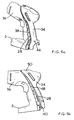
- FIG. 7 shows the rear view of the shrouding (34) once it is in place around the indented region (28) of the body (6).
- the mirror-image portions (2, 4) span the entire indented region (28) about their plane of registration X-X. It can also be seen from Figures 3 - 6 that the shrouding (34) totally surrounds and encapsulates the indented region (28) and, therefore, those parts of the body portions (2,4) within the indented region (28) also.
- the interface (38) is formed as a curved or arcuate surface.
- Such an arcuate surface is chosen to allow for accurate placement of the shrouding (34) as shown in Figures 3, 4, 5 & 6, which depict the way in which the shrouding (34) is attached to the indented region (28).
- any suitable shape of interface (38) will allow the advantages of the invention to accrue such as straight, stepped, castellated, etc.
- the extent to which the indented region needs to be formed along the relevant portion of the body (6) of the drill/driver is "substantial". Although no quantitative limits need to be placed upon this term, it is to be understood that one of the purposes of the shrouding (34) is to be able to overlie and encapsulate the entire indented region of the drill/driver body (6) and this enables a rigidity to the completed tool which has hithertofor not been available.
- the extent to which the indented region (28) subsists is very small in relation to the overall rear surface of the body (6) as shown in the attached drawings, then this object is unlikely to be achieved.
- the shrouding (34) is chosen to be of glass-filled nylon sub-structure with a resilient rubber over-moulding.
- the glass-filled nylon sub-structure is seen most readily from Figures 3-6 as reference numeral (48) and the rubber over-moulding as reference numeral (50).
- the method by which a rubber over-moulding (50) is held to a glass filled nylon substructure (48) is well known to those skilled in the art and so will not be discussed further herein.
- shrouding (34) There are different types or forms of shrouding (34) which can be chosen in accordance with the present invention dependent upon the purpose to which the shrouding (34) is put. For example, if the shrouding (34) is chosen simply to provide a rigid "cage" or shroud for the composite tool body (comprising the body portions (2, 4) and the shrouding element (34)) then glass-filled nylon or some other suitably hard plastics material is acceptable. Alternatively, should the purpose of the shrouding (34) be to aid in absorbing vibration of the drill/driver during use then the shrouding (34) may be formed of or include resilient material such as rubber or the like.
- detachable shrouding (34) it is possible to achieve various aesthetic design features, such as different coloured shroudings (34) to indicate, for example, the purpose to which the drill/driver is put, its torque, or power or speed outputs, etc. Alternatively, it may be used for altering decorative effects for that part of the drill/driver body.
- the mirror image body portions (2, 4) are brought into co-operable registration. This means that they are brought together about the plane which bisects the body longitudinally, namely X-X of Figure 1. Only when the two halves (2, 4) of the composite tool (6) are brought together in registration is the outline shape that is shown in the attached drawing. Clearly, if the 2 body portion halves (4, 6) do not register co-operably then they will be misaligned and the composite tool (6) will not be complete. Not only will this mean that the two halves (4, 6) cannot be coupled together, but also it will then not be possible for the shrouding (34) to be attached thereto.
Landscapes
- Engineering & Computer Science (AREA)
- Mechanical Engineering (AREA)
- Toys (AREA)
- Drilling And Boring (AREA)
- Scissors And Nippers (AREA)
- Professional, Industrial, Or Sporting Protective Garments (AREA)
Abstract
Description
Claims (7)
- A body for a power drill/driver formed from a plurality of moulded portions, two of which moulded portions are formed as mirror images of each other and are co-operable to define the body having a plane of portion registration, which plane of portion registration bisects the drill/driver body longitudinally;
the drill/driver body formed from co-operable registration of said two mirror-image portions also defining a forward aperture through which an output shaft of the drill/driver is accessible and a rearward section within which a motor of the drill/driver is housed and further defining a handle portion of the drill/driver directly adjacent the rearward portion thereof;
the surface of the drill/driver body so formed by co-operable registration of said two mirror-image portions also defining a region indented with respect to the remainder of the surface of the drill/driver, characterised in that;
the indented region not only spans each of the two mirror-image moulded portions, but also extends along a substantial portion of, and extends between, the rearward section and the handle portion of the drill/driver body;
the drill/driver body further including a detachable portion for removable attachment to the indented region of the drill/driver body;
and wherein the detachable portion, when attached to the drill/driver body, overlies and encapsulates the entire indented region of the drill/driver body. - A body for a power drill/driver according to claim 1 wherein the detachable portion forms a cover member for the indented region.
- A body for a power drill/driver according to either one of the preceding claims wherein the detachable portion may be formed from the same or different material from that of the drill/driver body, dependent upon the purpose for which the detachable portion is to be used.
- A body for a power drill/driver according to any one of the preceding claims wherein the indented region interfaces with the rearward section and the handle portion of the drill/driver via a curved or arcuate surface.
- A body for a power drill/driver according to claim 4 wherein the curved or arcuate surface is continuous.
- A body for a power drill/driver according to claim 5 wherein the continuous curved or arcuate surface from the rearward section to the handle portion.
- A body for a power tool according to any one of the preceding claims wherein the detachable member includes a plurality of bosses for aligning the detachable member with the moulded portions.
Applications Claiming Priority (2)
| Application Number | Priority Date | Filing Date | Title |
|---|---|---|---|
| GB0105140A GB0105140D0 (en) | 2001-03-02 | 2001-03-02 | Power tool body |
| GB0105140 | 2001-03-02 |
Publications (2)
| Publication Number | Publication Date |
|---|---|
| EP1236545A2 true EP1236545A2 (en) | 2002-09-04 |
| EP1236545A3 EP1236545A3 (en) | 2005-06-15 |
Family
ID=9909820
Family Applications (1)
| Application Number | Title | Priority Date | Filing Date |
|---|---|---|---|
| EP02004485A Withdrawn EP1236545A3 (en) | 2001-03-02 | 2002-02-27 | Power tool body |
Country Status (2)
| Country | Link |
|---|---|
| EP (1) | EP1236545A3 (en) |
| GB (1) | GB0105140D0 (en) |
Cited By (11)
| Publication number | Priority date | Publication date | Assignee | Title |
|---|---|---|---|---|
| GB2390562A (en) * | 2002-07-11 | 2004-01-14 | Bosch Gmbh Robert | Connection device for a hand-held power tool |
| GB2423274A (en) * | 2005-02-22 | 2006-08-23 | Bosch Gmbh Robert | Housing for a hand-held machine tool |
| US7117560B2 (en) * | 2004-07-28 | 2006-10-10 | Hsiu-Man Yu Chen | Handle of an adhesive-tape cutter able to accommodate articles |
| GB2428992A (en) * | 2005-08-08 | 2007-02-14 | Bosch Gmbh Robert | Electric hand tool with pot housing part and shell housing part |
| FR2894173A1 (en) * | 2005-12-01 | 2007-06-08 | Georges Renault Soc Par Action | Screwdriver for locking screws, has screw for assembling engine block, reduction case, handle and angle head according to assembling direction, and extending to exert assembling efforts according to assembling direction |
| DE102006041429A1 (en) * | 2006-09-04 | 2008-03-20 | Metabowerke Gmbh | Electric hand tool |
| WO2009115142A1 (en) | 2008-03-18 | 2009-09-24 | Robert Bosch Gmbh | Hand-held machine tool, in particular hand-guided grinding machine |
| WO2019211486A1 (en) * | 2018-05-04 | 2019-11-07 | Robert Bosch Gmbh | Machine tool housing |
| WO2019211211A1 (en) * | 2018-05-04 | 2019-11-07 | Robert Bosch Gmbh | Machine tool housing |
| WO2019211047A1 (en) * | 2018-05-04 | 2019-11-07 | Robert Bosch Gmbh | Electric screwdriver housing |
| WO2020002269A1 (en) * | 2018-06-29 | 2020-01-02 | Atlas Copco Industrial Technique Ab | Handheld electric power tool |
Family Cites Families (8)
| Publication number | Priority date | Publication date | Assignee | Title |
|---|---|---|---|---|
| DE4106768A1 (en) * | 1991-03-04 | 1992-09-10 | Licentia Gmbh | HAND-HELD ELECTRIC MACHINE TOOL WITH A SHELL PART MADE OF ELASTIC YELLOW MATERIAL ON THE HANDLE |
| JP2638750B2 (en) * | 1994-10-13 | 1997-08-06 | リョービ株式会社 | Power tool handle structure |
| DE19703746A1 (en) * | 1997-02-03 | 1998-08-06 | Scintilla Ag | Hand tool |
| JP3676609B2 (en) * | 1998-09-29 | 2005-07-27 | 株式会社マキタ | Mounting structure of hanging tool in electric power tool |
| DE29901003U1 (en) * | 1999-01-21 | 1999-04-01 | Chung, Lee-Hsin-Chih, Chung-Li, Taoyuan | Handle structure of a power tool |
| DE19918118B4 (en) * | 1999-04-22 | 2008-04-10 | Scintilla Ag | Soft grip element for electric hand tool machines |
| JP3918365B2 (en) * | 1999-06-02 | 2007-05-23 | 松下電工株式会社 | Battery power type electric tool housing manufacturing method |
| JP2001198856A (en) * | 2000-01-13 | 2001-07-24 | Hitachi Koki Co Ltd | Electric tool |
-
2001
- 2001-03-02 GB GB0105140A patent/GB0105140D0/en not_active Ceased
-
2002
- 2002-02-27 EP EP02004485A patent/EP1236545A3/en not_active Withdrawn
Cited By (20)
| Publication number | Priority date | Publication date | Assignee | Title |
|---|---|---|---|---|
| GB2390562A (en) * | 2002-07-11 | 2004-01-14 | Bosch Gmbh Robert | Connection device for a hand-held power tool |
| GB2390562B (en) * | 2002-07-11 | 2005-07-20 | Bosch Gmbh Robert | Hand tool machine |
| US7117560B2 (en) * | 2004-07-28 | 2006-10-10 | Hsiu-Man Yu Chen | Handle of an adhesive-tape cutter able to accommodate articles |
| GB2423274A (en) * | 2005-02-22 | 2006-08-23 | Bosch Gmbh Robert | Housing for a hand-held machine tool |
| GB2423274B (en) * | 2005-02-22 | 2007-05-23 | Bosch Gmbh Robert | Housing, fastening device for a housing and hand-held machine tool with a housing |
| GB2428992A (en) * | 2005-08-08 | 2007-02-14 | Bosch Gmbh Robert | Electric hand tool with pot housing part and shell housing part |
| GB2428992B (en) * | 2005-08-08 | 2007-11-21 | Bosch Gmbh Robert | Electric Hand Tool |
| FR2894173A1 (en) * | 2005-12-01 | 2007-06-08 | Georges Renault Soc Par Action | Screwdriver for locking screws, has screw for assembling engine block, reduction case, handle and angle head according to assembling direction, and extending to exert assembling efforts according to assembling direction |
| DE102006041429A1 (en) * | 2006-09-04 | 2008-03-20 | Metabowerke Gmbh | Electric hand tool |
| CN101977729B (en) * | 2008-03-18 | 2013-09-11 | 罗伯特·博世有限公司 | Hand-held machine tools, especially hand-held grinding machines |
| WO2009115142A1 (en) | 2008-03-18 | 2009-09-24 | Robert Bosch Gmbh | Hand-held machine tool, in particular hand-guided grinding machine |
| WO2019211486A1 (en) * | 2018-05-04 | 2019-11-07 | Robert Bosch Gmbh | Machine tool housing |
| WO2019211211A1 (en) * | 2018-05-04 | 2019-11-07 | Robert Bosch Gmbh | Machine tool housing |
| WO2019211047A1 (en) * | 2018-05-04 | 2019-11-07 | Robert Bosch Gmbh | Electric screwdriver housing |
| CN112074377A (en) * | 2018-05-04 | 2020-12-11 | 罗伯特·博世有限公司 | Electric bottle opener shell |
| CN112334280A (en) * | 2018-05-04 | 2021-02-05 | 罗伯特·博世有限公司 | Machine tool housing |
| CN112334280B (en) * | 2018-05-04 | 2024-08-09 | 罗伯特·博世有限公司 | Machine tool housing |
| CN112074377B (en) * | 2018-05-04 | 2024-10-29 | 罗伯特·博世有限公司 | Electric screwdriver housing |
| WO2020002269A1 (en) * | 2018-06-29 | 2020-01-02 | Atlas Copco Industrial Technique Ab | Handheld electric power tool |
| US11759939B2 (en) | 2018-06-29 | 2023-09-19 | Atlas Copco Industrial Technique Ab | Handheld electric power tool |
Also Published As
| Publication number | Publication date |
|---|---|
| EP1236545A3 (en) | 2005-06-15 |
| GB0105140D0 (en) | 2001-04-18 |
Similar Documents
| Publication | Publication Date | Title |
|---|---|---|
| US7845427B2 (en) | Sealing element of hand power tool housing | |
| US7252156B2 (en) | Vibration isolation handle | |
| CN105710847B (en) | Power tool and power tool Accessory Members | |
| USRE41098E1 (en) | Vehicle handlebar grip | |
| US20140196921A1 (en) | Power tool and auxiliary handle member | |
| AU2003213500B2 (en) | Power tool with integral gripping member | |
| US5813805A (en) | Spiral cutting tool with detachable handle | |
| US6112618A (en) | Bicycle Handgrip | |
| US20040134304A1 (en) | Handlebar grip for bicycle | |
| US8430183B2 (en) | Auxiliary handle, and hand power tool provided therewith | |
| US20140251649A1 (en) | Power tool assembly, power tool, and auxiliary handle member | |
| EP0886561B1 (en) | Tool handle | |
| EP1479486B1 (en) | Cushion grip handle | |
| CN1468184A (en) | Integral driver control system for joystick-operated vehicles | |
| US20120222525A1 (en) | Tool handle and method for manufacturing the same | |
| CN112720371A (en) | Electric tool shell and electric tool | |
| GB2425279A (en) | Chuck with a polymeric sleeve | |
| CN201659555U (en) | Dual-material combined device for pneumatic tool | |
| US6244130B1 (en) | Gripping device with a replaceable head portion for use on gear shift lever | |
| ITTO990102A1 (en) | HANDLEBAR FOR VEHICLE. | |
| CN1589996A (en) | Gripping device for clutch cover, front sleeve, rear sleeve and manufacturing method thereof | |
| CA2489082A1 (en) | Saw handle grip | |
| CN212354268U (en) | Improved small auxiliary handle-bar for bicycle | |
| US20030022744A1 (en) | Front gear-change device for bicycle | |
| JP3385349B2 (en) | Shift lever device for transmission |
Legal Events
| Date | Code | Title | Description |
|---|---|---|---|
| PUAI | Public reference made under article 153(3) epc to a published international application that has entered the european phase |
Free format text: ORIGINAL CODE: 0009012 |
|
| AK | Designated contracting states |
Kind code of ref document: A2 Designated state(s): AT BE CH CY DE DK ES FI FR GB GR IE IT LI LU MC NL PT SE TR |
|
| AX | Request for extension of the european patent |
Free format text: AL;LT;LV;MK;RO;SI |
|
| PUAL | Search report despatched |
Free format text: ORIGINAL CODE: 0009013 |
|
| AK | Designated contracting states |
Kind code of ref document: A3 Designated state(s): AT BE CH CY DE DK ES FI FR GB GR IE IT LI LU MC NL PT SE TR |
|
| AX | Request for extension of the european patent |
Extension state: AL LT LV MK RO SI |
|
| RIC1 | Information provided on ipc code assigned before grant |
Ipc: 7B 25F 5/00 B Ipc: 7B 25F 5/02 A |
|
| 17P | Request for examination filed |
Effective date: 20051205 |
|
| AKX | Designation fees paid |
Designated state(s): AT BE CH CY DE DK ES FI FR GB GR IE IT LI LU MC NL PT SE TR |
|
| 17Q | First examination report despatched |
Effective date: 20060904 |
|
| STAA | Information on the status of an ep patent application or granted ep patent |
Free format text: STATUS: THE APPLICATION IS DEEMED TO BE WITHDRAWN |
|
| 18D | Application deemed to be withdrawn |
Effective date: 20070116 |