EP1236527B1 - Machining method for difficult-to-machine material and machining tool therefor - Google Patents
Machining method for difficult-to-machine material and machining tool therefor Download PDFInfo
- Publication number
- EP1236527B1 EP1236527B1 EP02251378A EP02251378A EP1236527B1 EP 1236527 B1 EP1236527 B1 EP 1236527B1 EP 02251378 A EP02251378 A EP 02251378A EP 02251378 A EP02251378 A EP 02251378A EP 1236527 B1 EP1236527 B1 EP 1236527B1
- Authority
- EP
- European Patent Office
- Prior art keywords
- machining
- cutting
- chip
- workpiece
- difficult
- Prior art date
- Legal status (The legal status is an assumption and is not a legal conclusion. Google has not performed a legal analysis and makes no representation as to the accuracy of the status listed.)
- Expired - Lifetime
Links
- 238000003754 machining Methods 0.000 title claims description 31
- 238000000034 method Methods 0.000 title claims description 23
- 239000000463 material Substances 0.000 title claims description 13
- 229910052751 metal Inorganic materials 0.000 claims description 7
- 239000002184 metal Substances 0.000 claims description 7
- 238000005299 abrasion Methods 0.000 description 6
- MCMNRKCIXSYSNV-UHFFFAOYSA-N Zirconium dioxide Chemical compound O=[Zr]=O MCMNRKCIXSYSNV-UHFFFAOYSA-N 0.000 description 4
- 229910003460 diamond Inorganic materials 0.000 description 4
- 239000010432 diamond Substances 0.000 description 4
- 229910001018 Cast iron Inorganic materials 0.000 description 3
- 229910052804 chromium Inorganic materials 0.000 description 3
- 239000011651 chromium Substances 0.000 description 3
- 239000000919 ceramic Substances 0.000 description 2
- 229910010293 ceramic material Inorganic materials 0.000 description 2
- 230000003247 decreasing effect Effects 0.000 description 2
- 238000005240 physical vapour deposition Methods 0.000 description 2
- 229910052582 BN Inorganic materials 0.000 description 1
- PZNSFCLAULLKQX-UHFFFAOYSA-N Boron nitride Chemical compound N#B PZNSFCLAULLKQX-UHFFFAOYSA-N 0.000 description 1
- 240000004272 Eragrostis cilianensis Species 0.000 description 1
- 238000005452 bending Methods 0.000 description 1
- 239000010941 cobalt Substances 0.000 description 1
- 229910017052 cobalt Inorganic materials 0.000 description 1
- GUTLYIVDDKVIGB-UHFFFAOYSA-N cobalt atom Chemical compound [Co] GUTLYIVDDKVIGB-UHFFFAOYSA-N 0.000 description 1
- 230000001419 dependent effect Effects 0.000 description 1
- 238000005553 drilling Methods 0.000 description 1
- 238000005516 engineering process Methods 0.000 description 1
- UONOETXJSWQNOL-UHFFFAOYSA-N tungsten carbide Chemical compound [W+]#[C-] UONOETXJSWQNOL-UHFFFAOYSA-N 0.000 description 1
Images



Classifications
-
- B—PERFORMING OPERATIONS; TRANSPORTING
- B23—MACHINE TOOLS; METAL-WORKING NOT OTHERWISE PROVIDED FOR
- B23Q—DETAILS, COMPONENTS, OR ACCESSORIES FOR MACHINE TOOLS, e.g. ARRANGEMENTS FOR COPYING OR CONTROLLING; MACHINE TOOLS IN GENERAL CHARACTERISED BY THE CONSTRUCTION OF PARTICULAR DETAILS OR COMPONENTS; COMBINATIONS OR ASSOCIATIONS OF METAL-WORKING MACHINES, NOT DIRECTED TO A PARTICULAR RESULT
- B23Q5/00—Driving or feeding mechanisms; Control arrangements therefor
- B23Q5/02—Driving main working members
-
- B—PERFORMING OPERATIONS; TRANSPORTING
- B23—MACHINE TOOLS; METAL-WORKING NOT OTHERWISE PROVIDED FOR
- B23B—TURNING; BORING
- B23B27/00—Tools for turning or boring machines; Tools of a similar kind in general; Accessories therefor
-
- B—PERFORMING OPERATIONS; TRANSPORTING
- B23—MACHINE TOOLS; METAL-WORKING NOT OTHERWISE PROVIDED FOR
- B23B—TURNING; BORING
- B23B27/00—Tools for turning or boring machines; Tools of a similar kind in general; Accessories therefor
- B23B27/005—Geometry of the chip-forming or the clearance planes, e.g. tool angles
-
- B—PERFORMING OPERATIONS; TRANSPORTING
- B23—MACHINE TOOLS; METAL-WORKING NOT OTHERWISE PROVIDED FOR
- B23B—TURNING; BORING
- B23B29/00—Holders for non-rotary cutting tools; Boring bars or boring heads; Accessories for tool holders
- B23B29/04—Tool holders for a single cutting tool
- B23B29/12—Special arrangements on tool holders
- B23B29/125—Vibratory toolholders
-
- B—PERFORMING OPERATIONS; TRANSPORTING
- B23—MACHINE TOOLS; METAL-WORKING NOT OTHERWISE PROVIDED FOR
- B23B—TURNING; BORING
- B23B2200/00—Details of cutting inserts
- B23B2200/08—Rake or top surfaces
- B23B2200/086—Rake or top surfaces with one or more grooves
-
- Y—GENERAL TAGGING OF NEW TECHNOLOGICAL DEVELOPMENTS; GENERAL TAGGING OF CROSS-SECTIONAL TECHNOLOGIES SPANNING OVER SEVERAL SECTIONS OF THE IPC; TECHNICAL SUBJECTS COVERED BY FORMER USPC CROSS-REFERENCE ART COLLECTIONS [XRACs] AND DIGESTS
- Y10—TECHNICAL SUBJECTS COVERED BY FORMER USPC
- Y10T—TECHNICAL SUBJECTS COVERED BY FORMER US CLASSIFICATION
- Y10T407/00—Cutters, for shaping
- Y10T407/27—Cutters, for shaping comprising tool of specific chemical composition
-
- Y—GENERAL TAGGING OF NEW TECHNOLOGICAL DEVELOPMENTS; GENERAL TAGGING OF CROSS-SECTIONAL TECHNOLOGIES SPANNING OVER SEVERAL SECTIONS OF THE IPC; TECHNICAL SUBJECTS COVERED BY FORMER USPC CROSS-REFERENCE ART COLLECTIONS [XRACs] AND DIGESTS
- Y10—TECHNICAL SUBJECTS COVERED BY FORMER USPC
- Y10T—TECHNICAL SUBJECTS COVERED BY FORMER US CLASSIFICATION
- Y10T82/00—Turning
- Y10T82/10—Process of turning
Definitions
- the present invention relates to a machining tool and method as described in the preamble of claim 1, respectively claim 2.
- a tool, respectively method is known from document EP-A-1002604.
- the above-mentioned abrasive grinding method has problems that machining efficiency is low and that the method is hardly applicable to work for a complicated form such as grooving and screw-thread cutting so that development of a versatile machining method not relying on grinding is eagerly desired in machining technology.
- the present invention has an object to provide a highly efficient novel method of machining a high-hardness material, which is taken as difficult-to-machine in the prior art, using a machining tool made from a relatively inexpensive material, as well as to provide such a machining tool used in the method.
- the machining method for a workpiece made from a difficult-to-machine material comprises the features of claim 2.
- the machining tool of the present invention for use in the above-defined inventive machining method comprises the features of claim 1.
- An advantageous realisation of the method is disclosed in the dependent claim 3.
- Figure 1 is a schematic side view of a machining system for practicing the inventive machining method, in which a cutting tool 3 of the invention is mounted on the lower end of the ultrasonic vibrator 2 supported by the support 1 standing on a bed and the cutting tool 3 is put at the workpiece 4 rotating in the direction indicated by the arrow while the cutting tool 3 is under ultrasonic vibrations in the up-and-down direction indicated by the double-sided cranked arrow by operating the ultrasonic vibrator 2.
- the frequency of the ultrasonic vibrations is preferably in the range from 20 kHz to 75 kHz.
- the cutting tool 3 has a chip made from a cemented metal carbide such as those of tungsten carbide cemented with metallic cobalt and optionally coated by applying the PVD (physical vapor deposition) method.
- a cemented metal carbide such as those of tungsten carbide cemented with metallic cobalt
- PVD physical vapor deposition
- the inventive method under ultrasonic vibrations of the tool is applicable to a hardly machinable workpiece for which conventional diamond chip tools can never be used under ultrasonic vibration due to instantaneous chipping of the diamond chip.
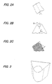
- Figures 2A, 2B and 2C are each a schematic illustration of the chip portion of the inventive machining tool, of which Figure 2A is a side elevational view of the chip, Figure 2B is a plan view of the chip showing the cutting face and Figure 2C is a cross sectional view of the chip as cut and viewed along the arrows IIC-IIC in Figure 2B.
- Figure 3 is a perspective view of the same chip.
- the chip is provided with a round-bottom groove having a radius of curvature r, which is preferably 0.2 to 0.5 mm, and running with an inclination angle of ⁇ , which is 15 to 60° or, preferably, 25 to 45°.
- the cemented metal carbide chip having the above defined grooved structure is subject to little chipping damage when used even in machining of a hardly machinable workpiece under ultrasonic vibration assist.
- the machining conditions in this case are not particularly limitative and can be conventional. Accordingly, the inventive method is industrially very advantageous because hardly machinable workpieces can be worked at a high efficiency by using a very inexpensive tool leading to a great reduction of the costs of machining work.
- the workpiece subjected to lathing work according to the invention was a sintered zirconia ceramic body having: a density of 5.98 g/cm 3 ; hardness of 91 HRA; bending strength of 1200 MPa; and Young's modulus of 190 GPa.
- Several cutting chips of a cemented metal carbide were prepared from commercially available chips of KC730 and UP20M ( supra ) by forming a round-bottom groove according to the invention.
- the grooves had an angle of inclination ⁇ of 0°, 15°, 30°, 45° or 60° and a radius of curvature r of the round bottom of 0.4 mm in each of the chips.
- the lathing test of the workpiece was conducted either without or with application of ultrasonic vibrations at a frequency of 40 kHz and with an amplitude of 11 ⁇ m as generated by the ultrasonic vibrator equipped in the machine system.
- the feed rate was 0.033 mm/revolution and the cutting speed was 11 m/minute.
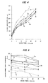
- Figures 4 and 5 The results of the lathing tests are shown in Figures 4 and 5, of which Figure 4 is a graph showing the major flank abrasion VB in ⁇ m and Figure 5 shows the undeformed chip thickness each as a function of the work time in minutes.
- the curves 1a to 1e and the curves 2a to 2e are for the results obtained without and with, respectively, application of the ultrasonic vibrations and the curves 1a and 2a, curves 1b and 2b, curves 1c and 2c, curves 1d and 2d and curves 1e and 2e are for the results obtained with the chips of which the round-bottom grooves had an inclination angle ⁇ of 0°, 15°, 30°, 45° and 60°, respectively.
- flank abrasion VB is usually increased as the work time is extended, it is understood from Figure 4 that the increase in VB is relatively small under application of the ultrasonic vibrations along with a relatively small dependency on the inclination angle ⁇ .
- the undeformed chip thickness h it is understood from Figure 5 that the values of h are generally large under application of the ultrasonic vibrations to give a higher working efficiency than in work without application of ultrasonic vibrations.
- Example 1 A machining test similar to that in Example 1 was undertaken using a workpiece of a quench-hardened high-chromium cast iron in place of the workpiece of sintered zirconia ceramic in Example 1.
- the lathing conditions included: an ultrasonic frequency of 20 kHz; feed rate of 0.05 mm/revolution; cutting speed of 10 m/minute; inclination angle ⁇ of the round-bottom groove in the chip of 30°; and cutting depth of 0.25 mm, the other parameters being the same as in Example 1.
- Figures 6, 7 and 8 The results of the lathing test are shown in Figures 6, 7 and 8, of which Figure 6 is a graph showing the cutting force P in kgf, Figure 7 is a graph showing the flank abrasion VB in ⁇ m and Figure 8 is a graph showing the undeformed chip thickness 2h/d each as a function of the work time t in minutes.
- the solid-line curves are for the tests with application of the ultrasonic vibrations and the broken-line curves are for the tests without application of the ultrasonic vibrations.
- the cutting force is recorded in three component forces including the major cutting force shown by the curves 3a and 4a, feed force shown by the curves 3b and 4b and thrust force shown by the curves 3c and 4c.
- each of the component forces of the cutting force i.e. major cutting force, feed force and thrust force
- Figure 7 indicates that the flank abrasion VB can be greatly decreased by the application of the ultrasonic vibrations leading to a corresponding extension of the durability life of the cutting tool.
- Figure 8 indicates that the undeformed chip thickness h can be increased by the application of the ultrasonic vibrations contributing to improvements in working efficiency and working accuracy.
Landscapes
- Engineering & Computer Science (AREA)
- Mechanical Engineering (AREA)
- Physics & Mathematics (AREA)
- Geometry (AREA)
- Turning (AREA)
- Grinding And Polishing Of Tertiary Curved Surfaces And Surfaces With Complex Shapes (AREA)
- Cutting Tools, Boring Holders, And Turrets (AREA)
Description
- The present invention relates to a machining tool and method as described in the preamble of
claim 1, respectively claim 2. Such a tool, respectively method, is known from document EP-A-1002604. - Since the hardness of a difficult-to-machine material such as fully sintered ceramic materials and quench-hardened high-chromium cast iron materials is extremely high, machining, e.g., cutting, lathing and drilling, of a workpiece of these materials cannot be conducted without using a diamond tool or CBN (cubic boron nitride) tool. Due to the expensiveness of these machining tools and their relatively short durability life resulting in high costs of the machine-worked products, abrasive grinding has heretofore been the only practical machining method for these difficult-to-machine materials.
- The above-mentioned abrasive grinding method, however, has problems that machining efficiency is low and that the method is hardly applicable to work for a complicated form such as grooving and screw-thread cutting so that development of a versatile machining method not relying on grinding is eagerly desired in machining technology.
- In view of the above described problems and disadvantages in the conventional machining method for difficult-to-machine materials, the present invention has an object to provide a highly efficient novel method of machining a high-hardness material, which is taken as difficult-to-machine in the prior art, using a machining tool made from a relatively inexpensive material, as well as to provide such a machining tool used in the method.
- Thus, the machining method for a workpiece made from a difficult-to-machine material provided by the invention comprises the features of
claim 2. - The machining tool of the present invention for use in the above-defined inventive machining method comprises the features of
claim 1. An advantageous realisation of the method is disclosed in thedependent claim 3. - In the drawings:
- Figure 1 is a schematic illustration of a side view of a machine for practicing the inventive method.
- Figures 2A, 2B and 2C are each an illustration showing the cutting chip of the inventive machining tool.
- Figure 3 is a perspective view of the cutting chip illustrated in Figures 2A to 2C.
- Figure 4 is a graph showing the major flank abrasion of the tool as a function of the work time in Example 1.
- Figure 5 is a graph showing the undeformed chip thickness as a function of the work time in Example 1.
- Figure 6 is a graph showing the cutting force as a function of the work time in Example 2.
- Figure 7 is a graph showing the major flank abrasion as a function of the work time in Example 2.
- Figure 8 is a graph showing the undeformed chip thickness as a function of the work time in Example 2.
-
- In the following, the present invention is described in detail with reference to the accompanying drawings.
- Figure 1 is a schematic side view of a machining system for practicing the inventive machining method, in which a
cutting tool 3 of the invention is mounted on the lower end of theultrasonic vibrator 2 supported by thesupport 1 standing on a bed and thecutting tool 3 is put at theworkpiece 4 rotating in the direction indicated by the arrow while thecutting tool 3 is under ultrasonic vibrations in the up-and-down direction indicated by the double-sided cranked arrow by operating theultrasonic vibrator 2. - The frequency of the ultrasonic vibrations is preferably in the range from 20 kHz to 75 kHz. The
cutting tool 3 has a chip made from a cemented metal carbide such as those of tungsten carbide cemented with metallic cobalt and optionally coated by applying the PVD (physical vapor deposition) method. Several grades of coated chips are available as commercial products including KC730 (a product by Kennametal, Inc.) and UP20M (a product by Mitsubishi Material Co.) which can be used advantageously in the inventive method. - The inventive method under ultrasonic vibrations of the tool is applicable to a hardly machinable workpiece for which conventional diamond chip tools can never be used under ultrasonic vibration due to instantaneous chipping of the diamond chip.
- Figures 2A, 2B and 2C are each a schematic illustration of the chip portion of the inventive machining tool, of which Figure 2A is a side elevational view of the chip, Figure 2B is a plan view of the chip showing the cutting face and Figure 2C is a cross sectional view of the chip as cut and viewed along the arrows IIC-IIC in Figure 2B. Figure 3 is a perspective view of the same chip. As is shown in these figures, the chip is provided with a round-bottom groove having a radius of curvature r, which is preferably 0.2 to 0.5 mm, and running with an inclination angle of , which is 15 to 60° or, preferably, 25 to 45°.
- Although, needless to say, chips of a cemented metal carbide are very inexpensive as compared with diamond chips, conventional cemented metal carbide chips cannot be used for machining of a difficult-to-machine material such as fully sintered ceramic materials and quench-hardened high-chromium cast iron materials in a conventional working procedure due to substantial abrasive wearing of the chip resulting in rapid loss of cutting power within a short time. According to the general understanding in the art, these conventional chips cannot be used also in ultrasonic vibration-assisted machining work because of instantaneous chipping of the chip.
- In contrast thereto, it is a quite unexpected discovery leading to the present invention that the cemented metal carbide chip having the above defined grooved structure is subject to little chipping damage when used even in machining of a hardly machinable workpiece under ultrasonic vibration assist. The machining conditions in this case are not particularly limitative and can be conventional. Accordingly, the inventive method is industrially very advantageous because hardly machinable workpieces can be worked at a high efficiency by using a very inexpensive tool leading to a great reduction of the costs of machining work.
- In the following, the present invention is described in more detail by way of Examples.
- The workpiece subjected to lathing work according to the invention was a sintered zirconia ceramic body having: a density of 5.98 g/cm3; hardness of 91 HRA; bending strength of 1200 MPa; and Young's modulus of 190 GPa. Several cutting chips of a cemented metal carbide were prepared from commercially available chips of KC730 and UP20M (supra) by forming a round-bottom groove according to the invention. The grooves had an angle of inclination of 0°, 15°, 30°, 45° or 60° and a radius of curvature r of the round bottom of 0.4 mm in each of the chips. The lathing test of the workpiece was conducted either without or with application of ultrasonic vibrations at a frequency of 40 kHz and with an amplitude of 11 µm as generated by the ultrasonic vibrator equipped in the machine system. The feed rate was 0.033 mm/revolution and the cutting speed was 11 m/minute.
- The results of the lathing tests are shown in Figures 4 and 5, of which Figure 4 is a graph showing the major flank abrasion VB in µm and Figure 5 shows the undeformed chip thickness each as a function of the work time in minutes. In these figures, the curves 1a to 1e and the
curves 2a to 2e are for the results obtained without and with, respectively, application of the ultrasonic vibrations and thecurves 1a and 2a,curves curves curves curves - While the flank abrasion VB is usually increased as the work time is extended, it is understood from Figure 4 that the increase in VB is relatively small under application of the ultrasonic vibrations along with a relatively small dependency on the inclination angle . With regard to the undeformed chip thickness h, it is understood from Figure 5 that the values of h are generally large under application of the ultrasonic vibrations to give a higher working efficiency than in work without application of ultrasonic vibrations.
- A machining test similar to that in Example 1 was undertaken using a workpiece of a quench-hardened high-chromium cast iron in place of the workpiece of sintered zirconia ceramic in Example 1. The lathing conditions included: an ultrasonic frequency of 20 kHz; feed rate of 0.05 mm/revolution; cutting speed of 10 m/minute; inclination angle of the round-bottom groove in the chip of 30°; and cutting depth of 0.25 mm, the other parameters being the same as in Example 1.
- The results of the lathing test are shown in Figures 6, 7 and 8, of which Figure 6 is a graph showing the cutting force P in kgf, Figure 7 is a graph showing the flank abrasion VB in µm and Figure 8 is a graph showing the
undeformed chip thickness 2h/d each as a function of the work time t in minutes. In these graphs, the solid-line curves are for the tests with application of the ultrasonic vibrations and the broken-line curves are for the tests without application of the ultrasonic vibrations. In Figure 6, the cutting force is recorded in three component forces including the major cutting force shown by thecurves curves curves - As is understood from Figure 6, each of the component forces of the cutting force, i.e. major cutting force, feed force and thrust force, is remarkably decreased by the application of the ultrasonic vibrations as compared with the tests without application of the ultrasonic vibrations. Figure 7 indicates that the flank abrasion VB can be greatly decreased by the application of the ultrasonic vibrations leading to a corresponding extension of the durability life of the cutting tool. In addition, Figure 8 indicates that the undeformed chip thickness h can be increased by the application of the ultrasonic vibrations contributing to improvements in working efficiency and working accuracy.
Claims (3)
- A machining tool (3) for machining of a workpiece, said workpiece being made from a difficult-to-machine material, said machine tool comprising:a cutting chip having a conically pointed end made from a cemented metal carbide, characterized in that said conically pointed end has a round-bottom groove running with an inclination of 15° to 60° relative to the cutting face of the chip, the round-bottom groove having a radius of curvature in the range from 0.2 mm to 0.5 mm.
- A method for machining of a workpiece of a difficult-to-machine material by the use of a machining tool according to claim 1 with a cutting chip made from a cemented metal carbide and having a conically pointed end, characterized in that said method comprises the steps of:(a) putting the end point of the cutting chip of the machining tool as defined in claim 1 at the workpiece to effect cutting of the workpiece; and(b) applying ultrasonic vibrations (2) to the cutting chip in the direction of cutting.
- The method as claimed in claim 2 in which the frequency of the ultrasonic vibrations is in the range from 20 kHz to 75 kHz.
Applications Claiming Priority (2)
| Application Number | Priority Date | Filing Date | Title |
|---|---|---|---|
| JP2001059319A JP3479688B2 (en) | 2001-03-02 | 2001-03-02 | Difficult-to-cut material cutting tools |
| JP2001059319 | 2001-03-02 |
Publications (2)
| Publication Number | Publication Date |
|---|---|
| EP1236527A1 EP1236527A1 (en) | 2002-09-04 |
| EP1236527B1 true EP1236527B1 (en) | 2003-12-10 |
Family
ID=18918895
Family Applications (1)
| Application Number | Title | Priority Date | Filing Date |
|---|---|---|---|
| EP02251378A Expired - Lifetime EP1236527B1 (en) | 2001-03-02 | 2002-02-27 | Machining method for difficult-to-machine material and machining tool therefor |
Country Status (4)
| Country | Link |
|---|---|
| US (1) | US20020121167A1 (en) |
| EP (1) | EP1236527B1 (en) |
| JP (1) | JP3479688B2 (en) |
| DE (1) | DE60200115T2 (en) |
Families Citing this family (7)
| Publication number | Priority date | Publication date | Assignee | Title |
|---|---|---|---|---|
| DE102005039026A1 (en) * | 2005-08-18 | 2007-02-22 | Saint-Gobain Diamantwerkzeuge Gmbh & Co. Kg | Method and apparatus for conditioning abrasive tools |
| WO2011052682A1 (en) * | 2009-11-02 | 2011-05-05 | 住友電工ハードメタル株式会社 | Method for processing difficult-to-cut cast iron |
| DE102012219254B4 (en) | 2012-10-22 | 2015-01-29 | Sauer Ultrasonic Gmbh | Supply circuit, supply system, tool actuator, tool |
| CN103894626B (en) * | 2014-04-10 | 2016-03-30 | 西安航空动力股份有限公司 | Certain type high-pressure turbine outer shroud is obturaged the processing method of sealing teeth on face |
| CN104227020B (en) * | 2014-07-21 | 2016-11-09 | 上海交通大学 | 40KHz dual-purpose ultrasonic assisted turning device |
| CN107096931A (en) * | 2017-05-18 | 2017-08-29 | 贵州大学 | A kind of hard alloy microflute lathe tool for cutting titanium alloy TC 4 |
| CN112620744B (en) * | 2020-12-10 | 2023-03-14 | 西北工业大学 | Ultrasonic vibration-assisted milling method of difficult-to-machine composite material TiB2/7050Al |
Family Cites Families (12)
| Publication number | Priority date | Publication date | Assignee | Title |
|---|---|---|---|---|
| GB2016350B (en) * | 1978-02-20 | 1982-05-26 | Citizen Watch Co Ltd | Ultrasonic cutting tool |
| JPH052243Y2 (en) * | 1984-09-18 | 1993-01-20 | ||
| JPS61154602U (en) * | 1985-03-19 | 1986-09-25 | ||
| JPS62208817A (en) * | 1986-03-07 | 1987-09-14 | Kobe Steel Ltd | Insert chip for milling cutter |
| GB2203978B (en) * | 1987-03-03 | 1991-06-12 | Taga Electric Co Ltd | Ultrasonic vibrational cutting apparatus |
| JPH065042Y2 (en) * | 1988-10-20 | 1994-02-09 | 三菱マテリアル株式会社 | Throwaway tip |
| JPH0694082B2 (en) * | 1989-04-17 | 1994-11-24 | 多賀電気株式会社 | Ultrasonic vibration processing device |
| SE500310C2 (en) * | 1990-12-03 | 1994-05-30 | Sandvik Ab | Cutting and cutting tool |
| JPH04322901A (en) * | 1991-04-24 | 1992-11-12 | Seiko Epson Corp | Ultrasonic vibration device |
| DE19523128C2 (en) * | 1994-08-09 | 1997-05-22 | Valenite Inc | Indexable insert |
| JPH1058208A (en) * | 1996-08-16 | 1998-03-03 | Nikon Corp | Cutting tool used for ultrasonic vibration cutting, and ultrasonic vibration cutting device using the same |
| SE513951C2 (en) * | 1998-11-20 | 2000-12-04 | Seco Tools Ab | Cut with S-shaped chip switch |
-
2001
- 2001-03-02 JP JP2001059319A patent/JP3479688B2/en not_active Expired - Lifetime
-
2002
- 2002-02-26 US US10/082,199 patent/US20020121167A1/en not_active Abandoned
- 2002-02-27 DE DE60200115T patent/DE60200115T2/en not_active Expired - Lifetime
- 2002-02-27 EP EP02251378A patent/EP1236527B1/en not_active Expired - Lifetime
Also Published As
| Publication number | Publication date |
|---|---|
| JP3479688B2 (en) | 2003-12-15 |
| JP2002263901A (en) | 2002-09-17 |
| EP1236527A1 (en) | 2002-09-04 |
| DE60200115D1 (en) | 2004-01-22 |
| US20020121167A1 (en) | 2002-09-05 |
| DE60200115T2 (en) | 2004-09-09 |
Similar Documents
| Publication | Publication Date | Title |
|---|---|---|
| CA2361633C (en) | Method for producing a cutting tool and a cutting tool | |
| US4802799A (en) | Drill bit | |
| US6161990A (en) | Cutting insert with improved flank surface roughness and method of making the same | |
| US5154550A (en) | Throw-away tipped drill bit | |
| Santhanam et al. | Cemented carbides | |
| US20120051854A1 (en) | Superhard insert | |
| EP1016479A2 (en) | Cutting tool | |
| WO2003106085A1 (en) | Cutting tool | |
| EP1236527A1 (en) | Machining method for difficult-to-machine material and machining tool therefor | |
| JP5394261B2 (en) | Substrate processing method | |
| Barnes et al. | Machining of aluminium based metal matrix composites | |
| RU2475338C2 (en) | Machining tool component | |
| WO2007069030A1 (en) | Ultra-hard cutting tool components | |
| EP1029624A2 (en) | Circular saw blades with cutting teeth composed of ultrahard tool material, and method for its production | |
| WO1995008423A1 (en) | Rotary cutting tool for working of wood or wood composite material | |
| JP3176877B2 (en) | Rotary cutting tool | |
| Heath | Ultrahard tool materials | |
| EP0852167A1 (en) | Coated cubic boron nitride polycrystalline superabrasive tools | |
| JP3188415B2 (en) | Reamer and hole finishing method using the same | |
| JP2505803B2 (en) | End mill | |
| KR102686399B1 (en) | Burnishing drill having joining structure of guide pad tip | |
| JP2002127102A (en) | Cutting cutter | |
| Somasundaram et al. | Acoustic emission studies while machining with coated tools | |
| Quinto | Cutting tools | |
| JPS62808Y2 (en) |
Legal Events
| Date | Code | Title | Description |
|---|---|---|---|
| PUAI | Public reference made under article 153(3) epc to a published international application that has entered the european phase |
Free format text: ORIGINAL CODE: 0009012 |
|
| AK | Designated contracting states |
Kind code of ref document: A1 Designated state(s): AT BE CH CY DE DK ES FI FR GB GR IE IT LI LU MC NL PT SE TR |
|
| AX | Request for extension of the european patent |
Free format text: AL;LT;LV;MK;RO;SI |
|
| 17P | Request for examination filed |
Effective date: 20021209 |
|
| GRAH | Despatch of communication of intention to grant a patent |
Free format text: ORIGINAL CODE: EPIDOS IGRA |
|
| AKX | Designation fees paid |
Designated state(s): DE FR GB |
|
| GRAS | Grant fee paid |
Free format text: ORIGINAL CODE: EPIDOSNIGR3 |
|
| GRAA | (expected) grant |
Free format text: ORIGINAL CODE: 0009210 |
|
| AK | Designated contracting states |
Kind code of ref document: B1 Designated state(s): DE FR GB |
|
| REG | Reference to a national code |
Ref country code: GB Ref legal event code: FG4D |
|
| REG | Reference to a national code |
Ref country code: IE Ref legal event code: FG4D |
|
| REF | Corresponds to: |
Ref document number: 60200115 Country of ref document: DE Date of ref document: 20040122 Kind code of ref document: P |
|
| ET | Fr: translation filed | ||
| PLBE | No opposition filed within time limit |
Free format text: ORIGINAL CODE: 0009261 |
|
| STAA | Information on the status of an ep patent application or granted ep patent |
Free format text: STATUS: NO OPPOSITION FILED WITHIN TIME LIMIT |
|
| 26N | No opposition filed |
Effective date: 20040913 |
|
| REG | Reference to a national code |
Ref country code: IE Ref legal event code: MM4A |
|
| PGFP | Annual fee paid to national office [announced via postgrant information from national office to epo] |
Ref country code: DE Payment date: 20110218 Year of fee payment: 10 Ref country code: FR Payment date: 20110302 Year of fee payment: 10 |
|
| PGFP | Annual fee paid to national office [announced via postgrant information from national office to epo] |
Ref country code: GB Payment date: 20110217 Year of fee payment: 10 |
|
| GBPC | Gb: european patent ceased through non-payment of renewal fee |
Effective date: 20120227 |
|
| REG | Reference to a national code |
Ref country code: FR Ref legal event code: ST Effective date: 20121031 |
|
| REG | Reference to a national code |
Ref country code: DE Ref legal event code: R119 Ref document number: 60200115 Country of ref document: DE Effective date: 20120901 |
|
| PG25 | Lapsed in a contracting state [announced via postgrant information from national office to epo] |
Ref country code: GB Free format text: LAPSE BECAUSE OF NON-PAYMENT OF DUE FEES Effective date: 20120227 Ref country code: FR Free format text: LAPSE BECAUSE OF NON-PAYMENT OF DUE FEES Effective date: 20120229 |
|
| PG25 | Lapsed in a contracting state [announced via postgrant information from national office to epo] |
Ref country code: DE Free format text: LAPSE BECAUSE OF NON-PAYMENT OF DUE FEES Effective date: 20120901 |