EP1236385B1 - Adapter kit zur erweiterung eines keilschlosses in einem kartenmodul - Google Patents
Adapter kit zur erweiterung eines keilschlosses in einem kartenmodul Download PDFInfo
- Publication number
- EP1236385B1 EP1236385B1 EP99966508A EP99966508A EP1236385B1 EP 1236385 B1 EP1236385 B1 EP 1236385B1 EP 99966508 A EP99966508 A EP 99966508A EP 99966508 A EP99966508 A EP 99966508A EP 1236385 B1 EP1236385 B1 EP 1236385B1
- Authority
- EP
- European Patent Office
- Prior art keywords
- circuit card
- chassis
- card module
- frame
- wedgelock
- Prior art date
- Legal status (The legal status is an assumption and is not a legal conclusion. Google has not performed a legal analysis and makes no representation as to the accuracy of the status listed.)
- Expired - Lifetime
Links
- 238000001816 cooling Methods 0.000 claims description 15
- 229910052751 metal Inorganic materials 0.000 description 6
- 239000002184 metal Substances 0.000 description 6
- 238000013461 design Methods 0.000 description 5
- 230000009467 reduction Effects 0.000 description 5
- 230000006872 improvement Effects 0.000 description 3
- 239000000463 material Substances 0.000 description 3
- 230000004048 modification Effects 0.000 description 3
- 238000012986 modification Methods 0.000 description 3
- 230000000694 effects Effects 0.000 description 2
- 230000003116 impacting effect Effects 0.000 description 2
- 238000000034 method Methods 0.000 description 2
- 238000005299 abrasion Methods 0.000 description 1
- 230000004075 alteration Effects 0.000 description 1
- 229910052782 aluminium Inorganic materials 0.000 description 1
- XAGFODPZIPBFFR-UHFFFAOYSA-N aluminium Chemical compound [Al] XAGFODPZIPBFFR-UHFFFAOYSA-N 0.000 description 1
- 238000004458 analytical method Methods 0.000 description 1
- 230000003416 augmentation Effects 0.000 description 1
- 230000008901 benefit Effects 0.000 description 1
- 239000004020 conductor Substances 0.000 description 1
- 238000007796 conventional method Methods 0.000 description 1
- 230000003247 decreasing effect Effects 0.000 description 1
- 230000007613 environmental effect Effects 0.000 description 1
- 230000007717 exclusion Effects 0.000 description 1
- 239000007788 liquid Substances 0.000 description 1
- 230000000717 retained effect Effects 0.000 description 1
- 238000012546 transfer Methods 0.000 description 1
Images



Classifications
-
- H—ELECTRICITY
- H05—ELECTRIC TECHNIQUES NOT OTHERWISE PROVIDED FOR
- H05K—PRINTED CIRCUITS; CASINGS OR CONSTRUCTIONAL DETAILS OF ELECTRIC APPARATUS; MANUFACTURE OF ASSEMBLAGES OF ELECTRICAL COMPONENTS
- H05K7/00—Constructional details common to different types of electric apparatus
- H05K7/20—Modifications to facilitate cooling, ventilating, or heating
- H05K7/20536—Modifications to facilitate cooling, ventilating, or heating for racks or cabinets of standardised dimensions, e.g. electronic racks for aircraft or telecommunication equipment
- H05K7/20545—Natural convection of gaseous coolant; Heat transfer by conduction from electronic boards
-
- H—ELECTRICITY
- H05—ELECTRIC TECHNIQUES NOT OTHERWISE PROVIDED FOR
- H05K—PRINTED CIRCUITS; CASINGS OR CONSTRUCTIONAL DETAILS OF ELECTRIC APPARATUS; MANUFACTURE OF ASSEMBLAGES OF ELECTRICAL COMPONENTS
- H05K7/00—Constructional details common to different types of electric apparatus
- H05K7/14—Mounting supporting structure in casing or on frame or rack
- H05K7/1401—Mounting supporting structure in casing or on frame or rack comprising clamping or extracting means
- H05K7/1402—Mounting supporting structure in casing or on frame or rack comprising clamping or extracting means for securing or extracting printed circuit boards
- H05K7/1404—Mounting supporting structure in casing or on frame or rack comprising clamping or extracting means for securing or extracting printed circuit boards by edge clamping, e.g. wedges
-
- Y—GENERAL TAGGING OF NEW TECHNOLOGICAL DEVELOPMENTS; GENERAL TAGGING OF CROSS-SECTIONAL TECHNOLOGIES SPANNING OVER SEVERAL SECTIONS OF THE IPC; TECHNICAL SUBJECTS COVERED BY FORMER USPC CROSS-REFERENCE ART COLLECTIONS [XRACs] AND DIGESTS
- Y10—TECHNICAL SUBJECTS COVERED BY FORMER USPC
- Y10T—TECHNICAL SUBJECTS COVERED BY FORMER US CLASSIFICATION
- Y10T403/00—Joints and connections
- Y10T403/76—Joints and connections having a cam, wedge, or tapered portion
Definitions
- the present invention pertains generally to the field of computer card modules and the frames contained within the modules. More specifically, the present invention relates generally to circuit card modules having frames that can be adapted to improve the cooling properties of the modules but optionally remain compliant with Institute of Electrical and Electronics Engineers (IEEE) specifications.
- IEEE Institute of Electrical and Electronics Engineers
- VMEs Versa Module Eurocards
- VMEs Versa Module Eurocards
- the cards In order to comply with the IEEE 1101.2 Specifications, the cards must be mechanically compliant with both chassis types. This requires an approximately 0.16 cm thick x 0.249 cm wide protrusion along the card edge to engage the convection-cooled chassis card guides. This protrusion is often an extension of the printed wiring board (PWB) or machined as part of PWB.
- PWB printed wiring board
- a challenge posed by the IEEE 1101.2 Specifications is that the card modules must be compatible with existing forced-air cooled chassis or racks, which do not use wedgelocks for heat exchange or mechanical mounting. Instead, the existing forced-air cooled chassis use the edge of the PWB as a guide and one of the mechanical attachment points for the chassis.
- the existing forced-air cooled chassis use the edge of the PWB as a guide and one of the mechanical attachment points for the chassis.
- air flow over the card is used to remove component heat.
- the component heat is removed by conduction to the chassis cold wall. The heat is then removed from the chassis by external means.
- the protrusion reduces the efficiency of heat removal by reducing the available conduction contact area and by reducing the size of the wedgelock that can be used. These two effects reduce the efficiency of movement of the heat to the cold wall of the chassis. Because of these legacy requirements, the conduction-cooled modules do not take full advantage of the area available at the cold wall of the chassis.
- the present invention is an improvement to a circuit card module including a adapter as defined by claim 1.
- the present invention is compatible with the IEEE 1101.2 Specifications.
- the present invention increases the conduction contact area between the chassis cold wall and the module.
- existing wedgelocks are increased in width from approximately 0.635 cm to approximately 0.889 cm.
- the wedgelock is mounted to one surface of the frame such that when installed in a conduction-cooled chassis, the opposite frame surface is forced against the chassis cold wall.
- the increased wedgelock size approximately doubles the clamping force applied with respect to conventional modules.
- the net effect of these improvements are a reduction in the thermal resistance per inch of wedgelock length in the range of, for example, approximately 0.42° C/W to approximately 0.21° C/W. This, in turn, reduces the module to chassis interface temperature rise.
- the improved thermal resistances and decreased temperature rises boost the reliability of the COTS circuit cards as compared to the prior art, particularly in the stringent environments experienced in military applications.
- FIGS. 1 through 5 The discussion of FIGS. 1 through 5 is related to a new stiffening frame (i.e., FIGS. 2, 4, and 5) that is being filed as a patent application on even date herewith with a title of "Interchangeable Stiffening Frame With Extended Width Wedgelock For Use in a Circuit Card Module" by the same inventors of the present invention.
- the discussion of FIGS. 1 through 5 provides a discussion of the problems experienced in the art and solutions thereto, and thus, this discussion has been retained for an understanding of the present invention.
- the present invention is depicted in FIG. 6 and the discussion thereof.
- FIG. 1 there is shown a cross-sectional view (top or side view) of a conventional circuit card module design installed in a conduction-cooled chassis 2.
- the module of FIG. 1 comprises two circuit cards: a mezzanine card 8 and a base card 7 although the number and type of cards can vary.
- a plurality of electrical components 6 e.g., integrated circuits, high-power die-up devices, etc.
- FIG. I illustrates component 6 mounted on card 7 only.
- Component 6 generates heat during its normal operation, and two thermal paths for heat removal are provided.
- the first thermal path is through the lower surface of component 6 to the end of circuit card 7 to chassis cold wall 2 via metal strip 5 (or shim).
- the metal strip 5 acts both as a heatsink and as protection for the card 7 against damage when it is inserted and removed from the chassis 2.
- the other thermal path for component 6 (shown by the dotted arrow in FIG. 1), and the primary one of interest, is through the top surface of component 6 to thermally-conductive heatsink 9 to module frame 1 and to chassis cold wall 2 via card 7 and metal strip 5.
- heatsink 9 and frame 1 can be constructed from one piece of material.
- An end portion of the circuit card 7 often includes a protrusion 4 (often machined from base card 7), which allows this module to be compliant with a convection-cooled chassis as defined in IEEE 1101.2 Specifications (see, e.g., FIG. 3 for a conventional 1101.2 compliant module used in a convection-cooled chassis).
- the hatch marks in FIG. 1 represent air gaps.
- the module of FIG. 1 fails to use approximately 40% of the cold wall of chassis 2 surface contact area available for thermal conduction; it uses only the surface contact area 10 for thermal conduction, which is typically about 0.635 cm in width. Additionally, for IEEE 1101.2 purposes, the module must be compliant with the convection-cooled chassis (see, e.g., FIG. 3) so it typically includes the protrusion 4.
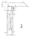
- the VME circuit card module illustrated in FIG. 2 a new stiffening frame, has improved cooling efficiency when used in a conduction-cooled chassis 2.
- the improved cooling efficiency is achieved, at least in part, through the use of a larger wedgelock 13.
- the wedgelock 3 of FIG. 1 is increased in width from x to x', e.g., from about 0.635 cm to about 0.889 cm. The width is not to be confused with the height which is the expandable portion of the wedgelock.
- the increased width x' of the wedgelock 13 identically increases the contact area 20 between the frame interchangeable 11 and the chassis cold wall 2.
- a second important result of the alteration or augmentation is that the frame 11 (a restructured frame 1 of FIG.
- the card 7' is either the same card 7 of FIG. 1 pulled back to allow for the placement of frame 11 or a modified/shortened version of card 7 with the protrusion 4 removed.
- the restructuring results in a frame 11 that optionally eliminates the protrusion 4 of FIG. I necessary for use with convection-cooled chassis (but not necessary in a conduction-cooled chassis) or optionally maintains the protrusion as in FIGS. 4 and 5. Further, the frame 11 eliminates the need for the metal strip 5 of FIG. 1. It should be noted that a reduction and simplification in thermal resistances is realized in the arrangement illustrated in FIG. 2, where it is reduced to about 0.1° C/W between the interchangeable frame 11 and chassis 2 cold wall.
- FIG. 2 is partially compliant with the IEEE 1101.2 Specifications as it does not include a protrusion for use in a convection-cooled chassis. Arrangement having frames that maintain the protrusion and still use a larger wedgelock for increased cooling efficiency are also contemplated, and are discussed below with respect to FIGS. 4 and 5.
- a commercially-available wedgelock 13 suitable for use in the present invention is the Card-Lok product which can be obtained from Calmark Corp., San Gabriel, CA.
- the adapter frame structure is designed to allow the use of large wedgelocks, e.g., those utilizing larger screws.
- the removal of the protrusion 4 allows for an increase in the width of the contact surface between the frame 1 and chassis 2 by from about 0.635 cm to about 0.889 cm.
- the larger wedgelock 13 exerts greater force between the frame 1 to the chassis cold wall 2 than the smaller wedgelock 3 of the prior art.
- the clamping force can be further increased by using a wedgelock 13 that has a friction-reducing finish applied to it and by installing the wedgelock 13 with washers.
- Wedgelocks made of aluminum are preferred, although other materials can be used.
- the increased force in combination with the additional contacting surface areas, significantly redeces the thermal resistance between the frame and the chassis 2 cold wall.
- typical thermal resistances across the wedgelock of conduction-cooled VME 6U modules is about 0.42° C/W.
- W Watt
- This temperature rise is significantly avoided using the adapter of the present invention.
- the reduction of thermal resistances and temperature rises is reflected in a reduced running temperature for component 6.
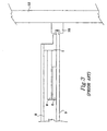
- FIG. 3 there is shown a prior art circuit card module that is compliant with the IEEE 1101.2 Specifications and is installed in a convection-cooled chassis 12.
- a card guide 18 is attached to the convection-cooled chassis 12 with for example, screws, for receiving the card 7 by its protrusion 4.
- the channel for receiving the protrusion 4 is machined into the chassis 2 itself as shown in FIGS. 1, 2, 5, and 6.
- the remaining structure of the circuit card module in FIG. 3 is similar to that discussed above with respect to FIG. 1 (similar reference numerals indicate similar components), with the exclusion of wedgelock 3 and strip 5 which are not present in convection-cooled applications, and need not be discussed again as its structure will be apparent to those skilled in the art.
- airflow for example, over the circuit card module removes the heat to the ambient environment.
- the VME circuit card module comprises a frame 21, which includes a protrusion 14 that fits in the card guide 18 of the chassis 12 as shown.
- the frame 21 allows for a larger wedgelock to be used and for the strip 5 to be eliminated.
- the remaining structure of the VME circuit card module in FIG. 4 is similar to that discussed above with respect to FIG. 2 (similar reference numerals indicate similar components) and need not be discussed again as its structure will be apparent to those skilled in the art.
- the wedgelock 3 would not be present. It is contemplated, however, that certain convection-cooled applications would require the use of an extended width wedgelock and thus, it is shown for purposes of illustration. For example, if the VME circuit card modules are integrated (first tested) in a commercial, convection-cooled chassis in a laboratory environment and then installed into the actual chassis, then an extended width wedgelock would be used.
- FIG. 5 there is shown an new stiffening frame as illustrated in FIG. 4 except that the VME circuit card module is mounted in a conduction-cooled chassis 2.
- This arrangement has a protrusion 14 and thus, is compliant with the IEEE 1101.2 Specifications.
- the arrangement of FIG. 5 has increased cooling efficiency but remains compatible with a convection-cooled chassis 12.
- the surface contact area 30 is not as large as the surface contact area 20 in FIG. 2.
- a reduction and simplification in thermal resistances is realized in the embodiments illustrated in FIG. 5, where it is reduced to only between the frame 21 and chassis cold wall 2 (strip 5 is eliminated). In any event, an extended width wedgelock allows for greater surface contact area 30 to improve the thermal performance.
- FIG. 6 there is shown a cross-sectional view of a COTS circuit card module modified with the adapter of the present invention to increase thermal efficiency using the principles described above (i.e., greater pressure from an extended width wedgelock, increased surface contact area 40, and extended frame to increase the conduction contact area).
- the VME circuit card module of FIG. 6 does not necessarily have to be compliant with the IEEE 1101.2 Specifications and can be any commercially-available circuit card. Many of the COTS conduction-cooled VME circuit card modules suffer from the thermal problems described above.
- the adapter of the present invention shown in FIG. 6 allows COTS circuit card modules to obtain the improved thermal performance and be in compliance with IEEE 1101.2 Specifications when used in a conduction-cooled chassis.
- the premise behind the present invention is to provide a wedgelock/chassis interface modification kit to existing modules to increase the cold wall contact area for improved cooling efficiency without a complete redesign of the PWB mechanical interface.
- the adapter of the present invention requires the removal of the COTS backside abrasion strip (strip 5 in FIG. 1), and potentially replacement of wedgelock 3 with an extended width wedgelock.
- the attached width dimension should not be confused with the height dimension which consists of the expandable portion of the wedgelock.
- the strip 15 (an element of the adapter) fully cooperates with the bottom surface of the card 7 and its protrusion 4 for an increased surface contact area 40, i.e., the air gaps of FIG. 1 (shown by hatch marks) between the chassis cold wall, the card 7, and the strip 5 are substantially filled by the adapter of the present invention.
- the interchangeable frame 1 is either adapted with another piece of material extension 16 to extend to the chassis 2 cold wall or is constructed of one piece (frame 1 integrated with extension 16).
- the adapter allows the COTS circuit card module to fully utilize the surface contact area 40 between the underside of card 7 and the chassis 2 cold wall, and optionally, the contact area between the wedgelock and frame 1 with extension 16.
- the wedgelock 3 can be an extended width wedgelock as described above with respect to FIGS. 2, 4, and 5 to further increase the contact area with the frame 1 and extension 16. Comparing the COTS circuit card module of FIG. 1 with that of FIG. 6, it can be seen that the air gaps (shown by hatch marks in FIG. 1) have been substantially filled by the adapter (i.e., elements 15 and 16) of the present invention.
- the frame 1 is extended with extension 16 to utilize the contact area 40, the width of wedgelock 3 can be extended, and the strip 15 fully utilizes the space under the protrusion 4.
- the configuration of FIG. 6 significantly reduces the thermal resistance between card 7, strip 15, and chassis 2 cold wall, which reduces the overall junction temperature of the components resulting in improved module reliability.
Landscapes
- Engineering & Computer Science (AREA)
- Microelectronics & Electronic Packaging (AREA)
- Aviation & Aerospace Engineering (AREA)
- Physics & Mathematics (AREA)
- Thermal Sciences (AREA)
- Cooling Or The Like Of Electrical Apparatus (AREA)
- Mounting Of Printed Circuit Boards And The Like (AREA)
Claims (5)
- Schaltkartenmodul, das mit einem leitungsgekühlten Gehäuse (2) zusammenarbeitet, in dem das Schaltkartenmodul aufgenommen wird, woraus erhöhte Kühlungsleistung resultiert, wobei das Schaltkartenmodul mindestens eine gedruckte Leiterplatte (PWB) (7, 8) aufweist, wobei die gedruckte Leiterplatte (7, 8) an einem ihrer Enden einen Vorsprung (4) aufweist, mindestens ein Bauelement (6), das mit der gedruckten Leiterplatte (7, 8) funktionsfähig verbunden ist, einen Wärmeweg zwischen dem Bauelement (6) und dem Gehäuse (2), und einen Rahmen (1), der mit der gedruckten Leiterplatte (7, 8) zum Versteifen der gedruckten Leiterplatte (7, 8) in Kontakt ist, wobei das Schaltkartenmodul einen Adapter umfasst, dadurch gekennzeichnet, dass
der Adapter einen thermisch leitenden Streifen (15) umfasst, der an einer Unterseite der gedruckten Leiterplatte (7) befestigt ist, wobei der Streifen (15) einen vorher festgelegten Oberflächenbereich der gedruckten Leiterplatte und des Vorsprunges (4) umfasst, und eine Rahmenerweiterung (16), die an einer Oberseite des Vorsprunges (4) befestigt ist, wobei die Rahmenerweiterung (16) im Wesentlichen den ganzen Bereich der Oberseite des Vorsprunges (4) umfasst. - Schaltkartenmodul nach Anspruch 1, wobei die Rahmenerweiterung (16) eine in den Rahmen (1) integrierte Rahmenerweiterung umfasst.
- Schaltkartenmodul nach Anspruch 1, wobei der Adapter aus zwei oder mehreren Teilen hergestellt ist.
- Schaltkartenmodul nach Anspruch 1, ferner ein Keilschloss (3) umfassend, das einen vorher festgelegten Oberflächenbereich des Rahmens (1) umfasst und eine Rahmenerweiterung (16), die den Adapter mittels Druck sicher an dem Gehäuse (2) befestigt, wobei das Keilschloss (3) ein Ausüben eines Druckes auf den vergrößerten Oberflächenbereich zwischen dem Adapter und dem Gehäuse (2) verursacht.
- Schaltkartenmodul nach Anspruch 4, wobei das Keilschloss (3) einen Temperaturanstieg pro Watt Leistungsverbrauch von ungefähr 0,21° C/W aufweist.
Applications Claiming Priority (3)
| Application Number | Priority Date | Filing Date | Title |
|---|---|---|---|
| US09/223,289 US6212075B1 (en) | 1998-12-30 | 1998-12-30 | Adapter kit to allow extended width wedgelock for use in a circuit card module |
| US223289 | 1998-12-30 | ||
| PCT/US1999/030458 WO2000041450A1 (en) | 1998-12-30 | 1999-12-20 | Adapter kit to allow extended width wedgelock for use in a circuit card module |
Publications (2)
| Publication Number | Publication Date |
|---|---|
| EP1236385A1 EP1236385A1 (de) | 2002-09-04 |
| EP1236385B1 true EP1236385B1 (de) | 2003-08-27 |
Family
ID=22835869
Family Applications (1)
| Application Number | Title | Priority Date | Filing Date |
|---|---|---|---|
| EP99966508A Expired - Lifetime EP1236385B1 (de) | 1998-12-30 | 1999-12-20 | Adapter kit zur erweiterung eines keilschlosses in einem kartenmodul |
Country Status (7)
| Country | Link |
|---|---|
| US (1) | US6212075B1 (de) |
| EP (1) | EP1236385B1 (de) |
| JP (1) | JP2003526199A (de) |
| CA (1) | CA2359101A1 (de) |
| DE (1) | DE69910848T2 (de) |
| IL (1) | IL144078A0 (de) |
| WO (1) | WO2000041450A1 (de) |
Families Citing this family (45)
| Publication number | Priority date | Publication date | Assignee | Title |
|---|---|---|---|---|
| IL130775A (en) * | 1999-07-02 | 2007-03-08 | Elta Systems Ltd | Conduction cooled electronic card module and method of producing the same utilizing an electronic circuit card originally designed for convection cooling |
| US20030025966A1 (en) * | 2001-08-03 | 2003-02-06 | Ross Halgren | OSP hardened WDM network |
| US6795316B2 (en) * | 2001-12-21 | 2004-09-21 | Redfern Broadband Networks, Inc. | WDM add/drop multiplexer module |
| WO2003056734A1 (en) * | 2001-12-21 | 2003-07-10 | Redfern Broadband Networks, Inc. | Improved wdm add/drop multiplexer module |
| US6873528B2 (en) * | 2002-05-28 | 2005-03-29 | Dy 4 Systems Ltd. | Supplemental heat conduction path for card to chassis heat dissipation |
| US6721182B1 (en) | 2002-10-10 | 2004-04-13 | Harris Corporation | Circuit card module including mezzanine card heat sink and related methods |
| US6768642B2 (en) * | 2002-12-16 | 2004-07-27 | Lockheed Martin Corporation | VME circuit host card with triple mezzanine configuration |
| US6678159B1 (en) * | 2002-12-23 | 2004-01-13 | Eastman Kodak Company | Method of transporting heat from a heat dissipating electrical assemblage |
| US6765798B1 (en) * | 2003-06-19 | 2004-07-20 | Curtiss-Wright Controls, Inc. | Electronic thermal management utilizing device with deflectable, two-leg conductive member; and with elastic, thermally-conductive material there between |
| US6963490B2 (en) * | 2003-11-10 | 2005-11-08 | Honeywell International Inc. | Methods and apparatus for conductive cooling of electronic units |
| US20050213306A1 (en) * | 2004-03-25 | 2005-09-29 | Lockheed Martin Corporation | Environmental control method and apparatus for electronic device enclosures |
| US7031167B1 (en) | 2004-11-24 | 2006-04-18 | Elta Systems Ltd. | Wedgelock for electronic circuit card module |
| US7254025B2 (en) * | 2005-02-02 | 2007-08-07 | National Instruments Corporation | Cooling mechanisms associated with card adapter |
| US7324336B2 (en) * | 2005-09-27 | 2008-01-29 | Lockheed Martin Corporation | Flow through cooling assemblies for conduction-cooled circuit modules |
| US7505251B2 (en) * | 2005-10-28 | 2009-03-17 | International Business Machines Corporation | Actuation mechanism for mating electronic card interconnect systems |
| US8703278B2 (en) * | 2006-03-28 | 2014-04-22 | Honeywell International Inc. | Light weight printed wiring board |
| US20070253169A1 (en) * | 2006-05-01 | 2007-11-01 | Honeywell International Inc. | Wedgelock device for increased thermal conductivity of a printed wiring wiring assembly |
| US7349221B2 (en) * | 2006-07-20 | 2008-03-25 | Honeywell International Inc. | Device for increased thermal conductivity between a printed wiring assembly and a chassis |
| US7408782B2 (en) * | 2007-01-04 | 2008-08-05 | Tellabs Bedford, Inc. | Multiple printed circuit board heat transfer guide plates |
| US20090080163A1 (en) * | 2007-05-17 | 2009-03-26 | Lockheed Martin Corporation | Printed wiring board assembly |
| US20090147472A1 (en) * | 2007-12-11 | 2009-06-11 | Honeywell International Inc. | Means to Utilize Conduction-cooled Electronics Modules in an Air Cooled System |
| US7995346B2 (en) * | 2008-03-06 | 2011-08-09 | Northrop Grumman Systems Corporation | Ruggedized, self aligning, sliding air seal for removable electronic units |
| JP4829279B2 (ja) * | 2008-08-27 | 2011-12-07 | 株式会社東芝 | 回路ユニットの放熱構造 |
| US7796384B2 (en) * | 2008-08-27 | 2010-09-14 | Honeywell International Inc. | Hybrid chassis cooling system |
| PL2359438T3 (pl) | 2008-11-20 | 2019-12-31 | Commscope Technologies Llc | Antena i szyk sektora dwuwiązkowego |
| US8222541B2 (en) * | 2009-06-19 | 2012-07-17 | General Electric Company | Avionics chassis |
| US8059409B2 (en) * | 2009-06-19 | 2011-11-15 | General Electric Company | Avionics chassis |
| US8023267B2 (en) | 2009-06-19 | 2011-09-20 | General Electric Company | Avionics chassis |
| US7911796B2 (en) * | 2009-06-19 | 2011-03-22 | General Electric Company | Avionics chassis |
| US8456846B2 (en) * | 2010-01-20 | 2013-06-04 | Wavetherm Corporation | Wedge based circuit board retainer |
| US8270172B2 (en) * | 2010-04-23 | 2012-09-18 | GE Intelligent Platforms Embedded Systems, Inc. | Wedge lock for use with a single board computer, a single board computer, and method of assembling a computer system |
| US8477500B2 (en) | 2010-05-25 | 2013-07-02 | General Electric Company | Locking device and method for making the same |
| JP2012023329A (ja) * | 2010-06-14 | 2012-02-02 | Toshiba Corp | 基板ユニット及び電子装置 |
| US8233279B2 (en) | 2010-11-04 | 2012-07-31 | Ge Intelligent Platforms, Inc. | Wedge lock for use with a single board computer and method of assembling a computer system |
| US9658000B2 (en) | 2012-02-15 | 2017-05-23 | Abaco Systems, Inc. | Flexible metallic heat connector |
| US9417670B2 (en) | 2012-08-07 | 2016-08-16 | Lockheed Martin Corporation | High power dissipation mezzanine card cooling frame |
| JP6319590B2 (ja) | 2012-10-08 | 2018-05-09 | ゼネラル・エレクトリック・カンパニイ | マイクロ流体素子を用いるlal反応性物質試験方法及び装置 |
| GB2529573B (en) | 2013-04-29 | 2017-04-19 | Ge Intelligent Platforms Embedded Systems Inc | Circuit card assembly with thermal energy removal |
| US9826662B2 (en) | 2013-12-12 | 2017-11-21 | General Electric Company | Reusable phase-change thermal interface structures |
| US9426931B2 (en) * | 2014-02-07 | 2016-08-23 | Lockheed Martin Corporation | Fluid-flow-through cooling of circuit boards |
| US10136557B2 (en) | 2015-12-04 | 2018-11-20 | General Electric Company | Thermal management systems and methods for heat generating electronics |
| US10470338B2 (en) * | 2017-01-10 | 2019-11-05 | Aselsan Elektronik Sanayi Ve Ticaret Anonim Sirketi | Cooling system |
| EP3905859B1 (de) | 2020-04-01 | 2023-08-30 | Hamilton Sundstrand Corporation | Thermische verwaltung von wicklungen und kernen planarer transformatoren |
| US11997815B2 (en) | 2020-04-01 | 2024-05-28 | Hamilton Sundstrand Corporation | Wedge lock support columns in electronic chassis |
| US12610490B2 (en) | 2024-02-12 | 2026-04-21 | Wavetherm Corporation | Wedge based circuit board retainer with dual end drivescrew |
Family Cites Families (23)
| Publication number | Priority date | Publication date | Assignee | Title |
|---|---|---|---|---|
| GB1326742A (en) | 1969-11-14 | 1973-08-15 | Lucas Industries Ltd | Mounting arrangement for electrical conductors |
| GB2103020B (en) | 1981-07-30 | 1985-03-20 | Marconi Avionics | Clamp arrangements for cooling electrical circuits |
| JPS59200495A (ja) | 1983-04-27 | 1984-11-13 | 株式会社日立製作所 | マルチチツプ・モジユ−ル |
| US4777561A (en) | 1985-03-26 | 1988-10-11 | Hughes Aircraft Company | Electronic module with self-activated heat pipe |
| US4751963A (en) * | 1986-07-03 | 1988-06-21 | Hughes Aircraft Company | Thermal conductance retainer for electronic printed circuit boards and the like |
| US4867235A (en) | 1986-10-20 | 1989-09-19 | Westinghouse Electric Corp. | Composite heat transfer means |
| US4879634A (en) * | 1987-11-13 | 1989-11-07 | Plessey Overseas Limited | Rack mounted circuit board |
| US4916575A (en) | 1988-08-08 | 1990-04-10 | Asten Francis C Van | Multiple circuit board module |
| US4853829A (en) | 1988-11-09 | 1989-08-01 | Eaton Corporation | Electronic module locking mechanism |
| JP2760829B2 (ja) | 1989-01-13 | 1998-06-04 | 株式会社日立製作所 | 電子基板 |
| US4994937A (en) | 1989-12-22 | 1991-02-19 | Lockheed Corporation | Hydraulic thermal clamp for electronic modules |
| DE4028003A1 (de) | 1990-09-04 | 1992-03-05 | Messerschmitt Boelkow Blohm | Klemmelement zur halterung von elektronik-karten |
| US5253963A (en) | 1991-12-11 | 1993-10-19 | Honeywell Inc. | Snap together wedgelock |
| FR2686213B1 (fr) | 1992-01-14 | 1994-05-06 | Applications Gles Elect Meca | Boitier recepteur de composants electroniques dissipateurs. |
| US5485353A (en) * | 1993-02-26 | 1996-01-16 | Eg&G Birtcher, Inc. | Retainer assembly |
| US5414592A (en) * | 1993-03-26 | 1995-05-09 | Honeywell Inc. | Heat transforming arrangement for printed wiring boards |
| US5280411A (en) | 1993-05-10 | 1994-01-18 | Southwest Research Institute | Packaging for an electronic circuit board |
| US5482109A (en) | 1994-03-15 | 1996-01-09 | E-Systems, Inc. | Modular heat exchanger |
| US5625227A (en) | 1995-01-18 | 1997-04-29 | Dell Usa, L.P. | Circuit board-mounted IC package cooling apparatus |
| US5559675A (en) | 1995-03-28 | 1996-09-24 | Twinhead International Corp. | Computer CPU heat dissipating and protecting device |
| US5549155A (en) | 1995-04-18 | 1996-08-27 | Thermacore, Inc. | Integrated circuit cooling apparatus |
| US5859764A (en) * | 1997-02-27 | 1999-01-12 | Raytheon Company | Electronics package employing a high thermal performance wedgelock |
| US5892658A (en) * | 1998-05-12 | 1999-04-06 | Lockhead Martin Corporation | VME eurocard triple printed wiring board single slot module assembly |
-
1998
- 1998-12-30 US US09/223,289 patent/US6212075B1/en not_active Expired - Lifetime
-
1999
- 1999-12-20 CA CA002359101A patent/CA2359101A1/en not_active Abandoned
- 1999-12-20 WO PCT/US1999/030458 patent/WO2000041450A1/en not_active Ceased
- 1999-12-20 DE DE69910848T patent/DE69910848T2/de not_active Expired - Fee Related
- 1999-12-20 IL IL14407899A patent/IL144078A0/xx not_active IP Right Cessation
- 1999-12-20 EP EP99966508A patent/EP1236385B1/de not_active Expired - Lifetime
- 1999-12-20 JP JP2000593075A patent/JP2003526199A/ja not_active Withdrawn
Also Published As
| Publication number | Publication date |
|---|---|
| DE69910848T2 (de) | 2004-07-08 |
| EP1236385A1 (de) | 2002-09-04 |
| CA2359101A1 (en) | 2000-07-13 |
| JP2003526199A (ja) | 2003-09-02 |
| IL144078A0 (en) | 2002-05-23 |
| WO2000041450A1 (en) | 2000-07-13 |
| US6212075B1 (en) | 2001-04-03 |
| DE69910848D1 (de) | 2003-10-02 |
Similar Documents
| Publication | Publication Date | Title |
|---|---|---|
| EP1149520B1 (de) | Austauschbar versteifungsleiste mit erweitertes keilschloss in einem kartenmodul | |
| US6212075B1 (en) | Adapter kit to allow extended width wedgelock for use in a circuit card module | |
| US5673176A (en) | Integrated circuit dual cooling paths and method for constructing same | |
| US6480382B2 (en) | Cooling device for hard disc | |
| US20040218354A1 (en) | Heat sink and package surface design | |
| US20020018336A1 (en) | Heat sink apparatus | |
| US20190200485A1 (en) | Mechanically flexible cold plates for low power components | |
| US20010050844A1 (en) | Structure for mounting radiating plate | |
| US6637505B1 (en) | Apparatus for cooling a box with heat generating elements received therein and a method for cooling same | |
| AU2005308439B2 (en) | Wedgelock for electronic circuit card module | |
| US20040070944A1 (en) | Circuit card module including mezzanine card heat sink and related methods | |
| US20040042178A1 (en) | Heat spreader with surface cavity | |
| US20170150643A1 (en) | Adapter cooling apparatus and method for modular computing devices | |
| US6201699B1 (en) | Transverse mountable heat sink for use in an electronic device | |
| US6483704B2 (en) | Microprocessor heat sink retention module | |
| US20080266806A1 (en) | Electronic assembly that includes a heat sink which cools multiple electronic components | |
| US6018460A (en) | Flexible thermal conductor with electromagnetic interference shielding capability for electronic components | |
| US6330160B1 (en) | Component retention clip for a heat sink assembly | |
| US6172873B1 (en) | Multi-electronic module mounting and retention mechanism | |
| US7254029B2 (en) | Printed circuit board with a heat dissipation device | |
| CN220307518U (zh) | 防静电的pcba主板 | |
| JPH0727677Y2 (ja) | ヒートシンクの冷媒流案内機構 | |
| US20240268063A1 (en) | Chassis for use in fanless and fan-cooled devices | |
| CN223786239U (zh) | 一种散热型线路板 | |
| CN218830758U (zh) | 一种散热型线路板 |
Legal Events
| Date | Code | Title | Description |
|---|---|---|---|
| PUAI | Public reference made under article 153(3) epc to a published international application that has entered the european phase |
Free format text: ORIGINAL CODE: 0009012 |
|
| 17P | Request for examination filed |
Effective date: 20010720 |
|
| AK | Designated contracting states |
Kind code of ref document: A1 Designated state(s): BE DE FR GB SE |
|
| GRAH | Despatch of communication of intention to grant a patent |
Free format text: ORIGINAL CODE: EPIDOS IGRA |
|
| GRAH | Despatch of communication of intention to grant a patent |
Free format text: ORIGINAL CODE: EPIDOS IGRA |
|
| GRAA | (expected) grant |
Free format text: ORIGINAL CODE: 0009210 |
|
| AK | Designated contracting states |
Designated state(s): BE DE FR GB SE |
|
| REG | Reference to a national code |
Ref country code: GB Ref legal event code: FG4D |
|
| REG | Reference to a national code |
Ref country code: IE Ref legal event code: FG4D |
|
| REF | Corresponds to: |
Ref document number: 69910848 Country of ref document: DE Date of ref document: 20031002 Kind code of ref document: P |
|
| REG | Reference to a national code |
Ref country code: SE Ref legal event code: TRGR |
|
| ET | Fr: translation filed | ||
| PLBE | No opposition filed within time limit |
Free format text: ORIGINAL CODE: 0009261 |
|
| STAA | Information on the status of an ep patent application or granted ep patent |
Free format text: STATUS: NO OPPOSITION FILED WITHIN TIME LIMIT |
|
| 26N | No opposition filed |
Effective date: 20040528 |
|
| REG | Reference to a national code |
Ref country code: IE Ref legal event code: MM4A |
|
| PGFP | Annual fee paid to national office [announced via postgrant information from national office to epo] |
Ref country code: GB Payment date: 20061106 Year of fee payment: 8 |
|
| PGFP | Annual fee paid to national office [announced via postgrant information from national office to epo] |
Ref country code: FR Payment date: 20061201 Year of fee payment: 8 |
|
| PGFP | Annual fee paid to national office [announced via postgrant information from national office to epo] |
Ref country code: SE Payment date: 20061204 Year of fee payment: 8 |
|
| PGFP | Annual fee paid to national office [announced via postgrant information from national office to epo] |
Ref country code: DE Payment date: 20061229 Year of fee payment: 8 |
|
| PGFP | Annual fee paid to national office [announced via postgrant information from national office to epo] |
Ref country code: BE Payment date: 20070109 Year of fee payment: 8 |
|
| BERE | Be: lapsed |
Owner name: *HONEYWELL INC. Effective date: 20071231 |
|
| EUG | Se: european patent has lapsed | ||
| GBPC | Gb: european patent ceased through non-payment of renewal fee |
Effective date: 20071220 |
|
| PG25 | Lapsed in a contracting state [announced via postgrant information from national office to epo] |
Ref country code: BE Free format text: LAPSE BECAUSE OF NON-PAYMENT OF DUE FEES Effective date: 20071231 |
|
| PG25 | Lapsed in a contracting state [announced via postgrant information from national office to epo] |
Ref country code: SE Free format text: LAPSE BECAUSE OF NON-PAYMENT OF DUE FEES Effective date: 20071221 Ref country code: DE Free format text: LAPSE BECAUSE OF NON-PAYMENT OF DUE FEES Effective date: 20080701 |
|
| REG | Reference to a national code |
Ref country code: FR Ref legal event code: ST Effective date: 20081020 |
|
| PG25 | Lapsed in a contracting state [announced via postgrant information from national office to epo] |
Ref country code: GB Free format text: LAPSE BECAUSE OF NON-PAYMENT OF DUE FEES Effective date: 20071220 |
|
| PG25 | Lapsed in a contracting state [announced via postgrant information from national office to epo] |
Ref country code: FR Free format text: LAPSE BECAUSE OF NON-PAYMENT OF DUE FEES Effective date: 20071231 |
|
| P01 | Opt-out of the competence of the unified patent court (upc) registered |
Effective date: 20230525 |