EP1236238B1 - Accumulator forming installation - Google Patents
Accumulator forming installation Download PDFInfo
- Publication number
- EP1236238B1 EP1236238B1 EP00985021A EP00985021A EP1236238B1 EP 1236238 B1 EP1236238 B1 EP 1236238B1 EP 00985021 A EP00985021 A EP 00985021A EP 00985021 A EP00985021 A EP 00985021A EP 1236238 B1 EP1236238 B1 EP 1236238B1
- Authority
- EP
- European Patent Office
- Prior art keywords
- installation
- accumulators
- pallets
- electrolyte
- loading
- Prior art date
- Legal status (The legal status is an assumption and is not a legal conclusion. Google has not performed a legal analysis and makes no representation as to the accuracy of the status listed.)
- Expired - Lifetime
Links
- 238000009434 installation Methods 0.000 title claims abstract description 62
- 239000003792 electrolyte Substances 0.000 claims abstract description 26
- 230000008878 coupling Effects 0.000 claims description 8
- 238000010168 coupling process Methods 0.000 claims description 8
- 238000005859 coupling reaction Methods 0.000 claims description 8
- 239000007789 gas Substances 0.000 claims description 4
- 230000013011 mating Effects 0.000 claims description 3
- 230000008030 elimination Effects 0.000 claims description 2
- 238000003379 elimination reaction Methods 0.000 claims description 2
- 238000004519 manufacturing process Methods 0.000 abstract description 5
- 238000000034 method Methods 0.000 description 6
- UFHFLCQGNIYNRP-UHFFFAOYSA-N Hydrogen Chemical compound [H][H] UFHFLCQGNIYNRP-UHFFFAOYSA-N 0.000 description 2
- 239000002253 acid Substances 0.000 description 2
- 239000001257 hydrogen Substances 0.000 description 2
- 229910052739 hydrogen Inorganic materials 0.000 description 2
- 230000001473 noxious effect Effects 0.000 description 2
- 239000000126 substance Substances 0.000 description 2
- 238000009825 accumulation Methods 0.000 description 1
- 150000007513 acids Chemical class 0.000 description 1
- 239000012141 concentrate Substances 0.000 description 1
- 230000005611 electricity Effects 0.000 description 1
- 230000008020 evaporation Effects 0.000 description 1
- 238000001704 evaporation Methods 0.000 description 1
- 238000005429 filling process Methods 0.000 description 1
- 238000012423 maintenance Methods 0.000 description 1
- 231100000331 toxic Toxicity 0.000 description 1
- 230000002588 toxic effect Effects 0.000 description 1
Images



Classifications
-
- H—ELECTRICITY
- H01—ELECTRIC ELEMENTS
- H01M—PROCESSES OR MEANS, e.g. BATTERIES, FOR THE DIRECT CONVERSION OF CHEMICAL ENERGY INTO ELECTRICAL ENERGY
- H01M50/00—Constructional details or processes of manufacture of the non-active parts of electrochemical cells other than fuel cells, e.g. hybrid cells
- H01M50/60—Arrangements or processes for filling or topping-up with liquids; Arrangements or processes for draining liquids from casings
-
- H—ELECTRICITY
- H01—ELECTRIC ELEMENTS
- H01M—PROCESSES OR MEANS, e.g. BATTERIES, FOR THE DIRECT CONVERSION OF CHEMICAL ENERGY INTO ELECTRICAL ENERGY
- H01M4/00—Electrodes
- H01M4/02—Electrodes composed of, or comprising, active material
- H01M4/04—Processes of manufacture in general
- H01M4/0438—Processes of manufacture in general by electrochemical processing
- H01M4/044—Activating, forming or electrochemical attack of the supporting material
- H01M4/0445—Forming after manufacture of the electrode, e.g. first charge, cycling
- H01M4/0447—Forming after manufacture of the electrode, e.g. first charge, cycling of complete cells or cells stacks
-
- H—ELECTRICITY
- H01—ELECTRIC ELEMENTS
- H01M—PROCESSES OR MEANS, e.g. BATTERIES, FOR THE DIRECT CONVERSION OF CHEMICAL ENERGY INTO ELECTRICAL ENERGY
- H01M10/00—Secondary cells; Manufacture thereof
- H01M10/06—Lead-acid accumulators
- H01M10/12—Construction or manufacture
- H01M10/128—Processes for forming or storing electrodes in the battery container
-
- H—ELECTRICITY
- H01—ELECTRIC ELEMENTS
- H01M—PROCESSES OR MEANS, e.g. BATTERIES, FOR THE DIRECT CONVERSION OF CHEMICAL ENERGY INTO ELECTRICAL ENERGY
- H01M50/00—Constructional details or processes of manufacture of the non-active parts of electrochemical cells other than fuel cells, e.g. hybrid cells
- H01M50/60—Arrangements or processes for filling or topping-up with liquids; Arrangements or processes for draining liquids from casings
- H01M50/609—Arrangements or processes for filling with liquid, e.g. electrolytes
-
- H—ELECTRICITY
- H01—ELECTRIC ELEMENTS
- H01M—PROCESSES OR MEANS, e.g. BATTERIES, FOR THE DIRECT CONVERSION OF CHEMICAL ENERGY INTO ELECTRICAL ENERGY
- H01M50/00—Constructional details or processes of manufacture of the non-active parts of electrochemical cells other than fuel cells, e.g. hybrid cells
- H01M50/60—Arrangements or processes for filling or topping-up with liquids; Arrangements or processes for draining liquids from casings
- H01M50/609—Arrangements or processes for filling with liquid, e.g. electrolytes
- H01M50/627—Filling ports
-
- Y—GENERAL TAGGING OF NEW TECHNOLOGICAL DEVELOPMENTS; GENERAL TAGGING OF CROSS-SECTIONAL TECHNOLOGIES SPANNING OVER SEVERAL SECTIONS OF THE IPC; TECHNICAL SUBJECTS COVERED BY FORMER USPC CROSS-REFERENCE ART COLLECTIONS [XRACs] AND DIGESTS
- Y02—TECHNOLOGIES OR APPLICATIONS FOR MITIGATION OR ADAPTATION AGAINST CLIMATE CHANGE
- Y02E—REDUCTION OF GREENHOUSE GAS [GHG] EMISSIONS, RELATED TO ENERGY GENERATION, TRANSMISSION OR DISTRIBUTION
- Y02E60/00—Enabling technologies; Technologies with a potential or indirect contribution to GHG emissions mitigation
- Y02E60/10—Energy storage using batteries
-
- Y—GENERAL TAGGING OF NEW TECHNOLOGICAL DEVELOPMENTS; GENERAL TAGGING OF CROSS-SECTIONAL TECHNOLOGIES SPANNING OVER SEVERAL SECTIONS OF THE IPC; TECHNICAL SUBJECTS COVERED BY FORMER USPC CROSS-REFERENCE ART COLLECTIONS [XRACs] AND DIGESTS
- Y02—TECHNOLOGIES OR APPLICATIONS FOR MITIGATION OR ADAPTATION AGAINST CLIMATE CHANGE
- Y02P—CLIMATE CHANGE MITIGATION TECHNOLOGIES IN THE PRODUCTION OR PROCESSING OF GOODS
- Y02P70/00—Climate change mitigation technologies in the production process for final industrial or consumer products
- Y02P70/50—Manufacturing or production processes characterised by the final manufactured product
-
- Y—GENERAL TAGGING OF NEW TECHNOLOGICAL DEVELOPMENTS; GENERAL TAGGING OF CROSS-SECTIONAL TECHNOLOGIES SPANNING OVER SEVERAL SECTIONS OF THE IPC; TECHNICAL SUBJECTS COVERED BY FORMER USPC CROSS-REFERENCE ART COLLECTIONS [XRACs] AND DIGESTS
- Y10—TECHNICAL SUBJECTS COVERED BY FORMER USPC
- Y10T—TECHNICAL SUBJECTS COVERED BY FORMER US CLASSIFICATION
- Y10T29/00—Metal working
- Y10T29/49—Method of mechanical manufacture
- Y10T29/49002—Electrical device making
- Y10T29/49108—Electric battery cell making
-
- Y—GENERAL TAGGING OF NEW TECHNOLOGICAL DEVELOPMENTS; GENERAL TAGGING OF CROSS-SECTIONAL TECHNOLOGIES SPANNING OVER SEVERAL SECTIONS OF THE IPC; TECHNICAL SUBJECTS COVERED BY FORMER USPC CROSS-REFERENCE ART COLLECTIONS [XRACs] AND DIGESTS
- Y10—TECHNICAL SUBJECTS COVERED BY FORMER USPC
- Y10T—TECHNICAL SUBJECTS COVERED BY FORMER US CLASSIFICATION
- Y10T29/00—Metal working
- Y10T29/53—Means to assemble or disassemble
- Y10T29/53113—Heat exchanger
-
- Y—GENERAL TAGGING OF NEW TECHNOLOGICAL DEVELOPMENTS; GENERAL TAGGING OF CROSS-SECTIONAL TECHNOLOGIES SPANNING OVER SEVERAL SECTIONS OF THE IPC; TECHNICAL SUBJECTS COVERED BY FORMER USPC CROSS-REFERENCE ART COLLECTIONS [XRACs] AND DIGESTS
- Y10—TECHNICAL SUBJECTS COVERED BY FORMER USPC
- Y10T—TECHNICAL SUBJECTS COVERED BY FORMER US CLASSIFICATION
- Y10T29/00—Metal working
- Y10T29/53—Means to assemble or disassemble
- Y10T29/5313—Means to assemble electrical device
- Y10T29/53135—Storage cell or battery
-
- Y—GENERAL TAGGING OF NEW TECHNOLOGICAL DEVELOPMENTS; GENERAL TAGGING OF CROSS-SECTIONAL TECHNOLOGIES SPANNING OVER SEVERAL SECTIONS OF THE IPC; TECHNICAL SUBJECTS COVERED BY FORMER USPC CROSS-REFERENCE ART COLLECTIONS [XRACs] AND DIGESTS
- Y10—TECHNICAL SUBJECTS COVERED BY FORMER USPC
- Y10T—TECHNICAL SUBJECTS COVERED BY FORMER US CLASSIFICATION
- Y10T29/00—Metal working
- Y10T29/53—Means to assemble or disassemble
- Y10T29/53435—Means to assemble or disassemble including assembly pallet
Definitions
- the invention concerns an installation for the forming of accumulators, particularly suitable for the rapid filling and charging of lead accumulators.
- the forming process of the accumulators has to be understood as the charge of electricity of the accumulators before the use of them.
- a plurality of accumulators is placed on roller support surfaces that make it possible to move them along the production line.
- the accumulators reach a first filling station, where the electrolyte is fed into the accumulator.
- an operator connects the poles of each accumulator to an electric network that, powered by a suitable power unit, supplies the electric energy that is necessary to charge the accumulators.
- an operator disconnects the accumulators from the electric network and conveys them to a second filling station, where each accumulator is first emptied and then filled again with electrolyte with final density.
- Another known type of installation features the forced circulation of the electrolyte inside the accumulator, during the charging phase.
- JP10106614 A discloses an accumulator forming installation comprising a high frame like casing with projecting supports positioned side by side to accommodate the accumulators, a loading and unloading station, power supply means, electrolyte feeding means, a lift conveyor with handling means for moving the accumulators to the frames and suction means comprising an aspirator.
- EP 0406464 A discloses an accumulator forming station with a fixed arrangement.
- the installation comprises a casing, a plurality of horizontal pallets by which the accumulators are supported,, power supply means, electrolyte feeding means and suction means comprising an aspirator.
- the aim of the present invention is to overcome the above mentioned drawbacks.
- One of the first goals of the invention is the implementation of an accumulator forming installation that, though maintaining the number of accumulators treated at the same time unchanged, should occupy a quite smaller surface than the known installations, thus reducing the installation costs considerably.
- a further aim is the implementation of an installation that should make it possible to reduce the necessary personnel, though maintaining the same productivity as the known installations.
- Another aim of the present invention is that the installation, during the forming of the elements, should make it possible to control the noxious gases developed during the process in the best possible way, so that the operators in charge with the installation don't have any contact with these gases.
- the present invention is also aimed at implementing a modular installation that may be adapted and enlarged according to the needs.
- the installation subject of the invention makes it possible to considerably increase the productivity of the accumulator forming process compared with the known installations.
- the installation subject of the invention can be introduced in a continuous accumulator production line.
- the installation subject of the invention makes it possible to concentrate the accumulator filling process and the effective charging in the rapid charging phase, thus reducing production times.
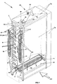
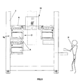
- FIG. 1 The accumulator forming installation of the invention is represented in FIG. 1, where it is indicated as a whole by 1, and comprises a plurality of pallets 2 on/from which the accumulators A to be formed are placed/collected in correspondence with the loading/unloading stations 3 and 4, power supply means 5 and electrolyte feeding means 6 for the accumulators A to be formed.
- the invention comprises a casing 7 provided with a plurality of projecting supports 8 positioned side by side and aligned in vertical direction, suitable for supporting the pallets 2 by placing them one on top of the other, in such a way as to create the same number of forming stations 9 for the accumulators A to be formed, and handling means, indicated as a whole by 10, suitable for moving the pallets 2 among the loading and unloading stations 3 and 4 and the forming stations 9.
- the loading station 3 and the unloading station 4 coincide and are defined by the pair of lower projecting supports 11 arranged on the two sides of the casing 7 and by the plane 12 situated between them.
- each one of said pallets 2 the power supply means 5 and the electrolyte feeding means 6 are positioned, as shown in detail in FIG. 2, below the ideal line, indicated by 8L, along which each pallet 2 is suspended from the respective projecting supports 8 and handling means 10.
- handling means 10 As far as the handling means 10 are concerned, they comprise travel means 13, visible in detail in FIG. 3, and lifting means 18, visible in detail in FIG. 1.
- the travel means 13 comprise first powering means 14 and first kinematic units 15 provided with coupling means 16 suitable for mating to second coupling means 17 present on each pallet 2, in order to ensure the coupling and the successive shifting of the pallet 2 along the horizontal direction O, while the lifting means 18 comprise second powering means 19 and second kinematic units 20 that permit the movement of each pallet 2 along the vertical direction V.
- the pallets 2 are vertically spaced from one another of a distance 21 that cannot be shorter than the height 22 of the accumulators A supported by each pallet.
- each pallet 2 is provided with sliding means, indicated as a whole by 23, suitable for facilitating its movement towards or away from the loading/unloading stations 3 and 4 and towards or away from each projecting support 8 and constituted by idle rollers 24, and said sliding means, according to a variant application of the invention, can be present on the projecting supports 8 or on the handling means 10 or on both of them.
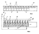
- the power supply means represented in detail in FIGURES 4 and 5, where they are indicated as a whole by 5, they comprise a collector cable 25 integral with each pallet 2 and connected, by means of a flexible cable 26 visible in FIG. 1, to a continuous power unit not shown in the figure and provided with a plurality of electric terminals 27 with removable connectors 28 for the connection to the respective poles, positive and negative, of each one of the accumulators A to be formed.
- the removable connectors 28 connect the accumulators A to be formed preferably, but not necessarily in series.
- electrolyte feeding means 6 As to the electrolyte feeding means 6, also visible in FIGURES 4-5, they comprise two manifolds for the feeding and return of the electrolyte, indicated respectively by 29 and 30, each one integral with each pallet 2 and connected, through the same number of flexible pipes 31 shown in FIG. 1, to a feed and return unit that is not represented in the figure.
- the feed and return unit provides for the forced circulation of the electrolyte inside each accumulator A, as required by the forming and charging process, also preventing the accumulation of hydrogen. It is well known, in fact, that during the forming process hydrogen is developed, which is highly flammable if present in the atmosphere in a percentage exceeding 4%.
- Each manifold 29 and 30 is also provided with a plurality of pipes connected to the same number of filling elements 32 that can be removably connected to the filling holes of each accumulator to be formed A.
- Each filling element 32 is preferably of the already known type.
- the pallets 2 they comprise a support surface 35 for the accumulators A to be formed, said support surface being developed longitudinally and being visible in particular in FIG. 3. Said surface is supported at the ends by a substantially U-shaped bearing structure 36, in which the second coupling means 17 are provided and which supports the collector cable 25 and the two manifolds 29 and 30.
- suction means indicated as a whole by 33, for the gases developed in each accumulator, comprising in particular an aspirator 37 positioned above the casing 7.
- the suction means is necessary, since it permits the elimination of any toxic vapours that may be inhaled by the operator in charge with the installation.
- the suction is more effective thanks to the presence of a plurality of panels 7a positioned on the casing perimeter and surrounding the installation.
- An automatic fire fighting system may be placed inside said space, and it should preferably be of the type with chemical extinguisher.
- the installation is designed so that the accumulators A to be formed coming from the assembly line reach the loading station 3, for example by means of a conveyor belt.
- An operator P places them on the pallet 2, connects each removable connector 28 to the corresponding poles of each accumulator A and inserts the filling element 32 in the corresponding electrolyte filling holes of each accumulator A, thus guaranteeing the supply of power and electrolyte.
- the travel means 13 automatically provide for shifting the pallet 2 horizontally and placing it in the free forming station 9a, as shown in FIG. 9.
- the accumulators A to be formed positioned on the respective forming stations 9 undergo the filling, forming and charging cycle, after which, with a procedure analogue to that described above, but performed in the reverse order, are collected from each forming station and brought to the unloading station 4, where the operator provides for removing them.
- each forming station 9 the cycle of the accumulators A to be formed positioned on each forming station 9 is controlled by an intelligent unit, not represented in the figures, which provides for the coordination of the travel means 13 and lifting means 18 and controls the operation of the suction installation and the capacity of the electrolyte feeding installation and of the power supply installation.
- FIG. 10 A variant application of the described installation, represented in FIG. 10, where it is indicated as a whole by 100, is differentiated from the previous one by the fact that the handling means do not belong to the casing 7.
- said handling means 10a are constituted by a trilateral forklift M that makes it possible to collect the accumulators, previously positioned side by side on a surface 44, and then places them on each forming station defined by the casings 70.
- the filling element 32 and each removable connector 28 are integral with a bearing element 45 developed longitudinally and supported at its ends by actuators, comprising for example a pair of pneumatic jacks 46 fixed to the support structure 170.
- each pneumatic jack 46 controlled by the intelligent control unit, has the cylinder 46a fixed to the support structure 170 and the rod 46b hinged to the bearing element 45.
- control unit operates the jacks 46 and moves the bearing element 45 in a substantially vertical direction, until each filling element 32 is connected to each electrolyte filling hole and each removable connector 28 is connected to each pole.
Landscapes
- Chemical & Material Sciences (AREA)
- Chemical Kinetics & Catalysis (AREA)
- Electrochemistry (AREA)
- General Chemical & Material Sciences (AREA)
- Engineering & Computer Science (AREA)
- Manufacturing & Machinery (AREA)
- Secondary Cells (AREA)
- Battery Mounting, Suspending (AREA)
- Supports For Pipes And Cables (AREA)
- Supply Devices, Intensifiers, Converters, And Telemotors (AREA)
- Devices For Conveying Motion By Means Of Endless Flexible Members (AREA)
- Buildings Adapted To Withstand Abnormal External Influences (AREA)
- Percussion Or Vibration Massage (AREA)
- Automatic Assembly (AREA)
- Bridges Or Land Bridges (AREA)
- Road Signs Or Road Markings (AREA)
- Sealing Battery Cases Or Jackets (AREA)
- Charge And Discharge Circuits For Batteries Or The Like (AREA)
- Control Of Eletrric Generators (AREA)
- Holo Graphy (AREA)
Abstract
Description
- The invention concerns an installation for the forming of accumulators, particularly suitable for the rapid filling and charging of lead accumulators.
- The forming process of the accumulators has to be understood as the charge of electricity of the accumulators before the use of them.
- According to the known installations used for the forming of lead accumulators, a plurality of accumulators is placed on roller support surfaces that make it possible to move them along the production line.
- In particular, in a first type of installations the accumulators reach a first filling station, where the electrolyte is fed into the accumulator.
- Successively, an operator connects the poles of each accumulator to an electric network that, powered by a suitable power unit, supplies the electric energy that is necessary to charge the accumulators.
- After the charging phase, which lasts from 18 to 24 hours in total, an operator disconnects the accumulators from the electric network and conveys them to a second filling station, where each accumulator is first emptied and then filled again with electrolyte with final density.
- Another known type of installation features the forced circulation of the electrolyte inside the accumulator, during the charging phase.
- This ensures considerable reduction in the accumulator charging time, provided that some parameters like the density and temperature of the acids are kept constant.
- It is important to consider that the complex electric and hydraulic networks constituting the installation make it necessary to develop it on a substantially horizontal plane.
- The main drawback of the described installations is represented by the fact that, being substantially developed on a horizontal plane, they occupy large surfaces, which considerably influences the implementation and maintenance costs of the installation itself.
- In particular, the cost of the racks constitutes a considerable share of the total expenses required for the implementation of the structure.
- Another drawback is represented by the fact that the operators inhale noxious substances deriving from the evaporation of the acid solutions present inside the accumulator.
- JP10106614 A discloses an accumulator forming installation comprising a high frame like casing with projecting supports positioned side by side to accommodate the accumulators, a loading and unloading station, power supply means, electrolyte feeding means, a lift conveyor with handling means for moving the accumulators to the frames and suction means comprising an aspirator.
- EP 0406464 A discloses an accumulator forming station with a fixed arrangement. The installation comprises a casing, a plurality of horizontal pallets by which the accumulators are supported,, power supply means, electrolyte feeding means and suction means comprising an aspirator.
- The aim of the present invention is to overcome the above mentioned drawbacks.
- One of the first goals of the invention is the implementation of an accumulator forming installation that, though maintaining the number of accumulators treated at the same time unchanged, should occupy a quite smaller surface than the known installations, thus reducing the installation costs considerably.
- A further aim is the implementation of an installation that should make it possible to reduce the necessary personnel, though maintaining the same productivity as the known installations.
- Another aim of the present invention is that the installation, during the forming of the elements, should make it possible to control the noxious gases developed during the process in the best possible way, so that the operators in charge with the installation don't have any contact with these gases.
- The present invention is also aimed at implementing a modular installation that may be adapted and enlarged according to the needs.
- The aims mentioned above have been achieved through the implementation of an installation for forming accumulators that, according to the main claim, comprises:
- a plurality of pallets adapted to support a plurality of accumulators aligned in a side-by-side relationship on said pallet;
- at least one loading station for loading of said accumulators to said pallets;
- at least one unloading station for unloading said accumulators from said pallets;
- power supply means for charging said accumulators; and
- electrolyte feeding means for feeding electrolyte to said accumulators,
- a casing for filling and charging said accumulators, said casing including a plurality of projecting supports positioned in a side-by-side relationship and aligned in a generally vertical orientation such that positioning of said supports in said vertical orientation provides a plurality of forming stations, said supporting means further adapted to support said pallets in a substantially horizontal position arranged one on top of the other in said vertical orientation;
- said casing further including said electrolyte feeding means operatively associated with accumulators for feeding electrolyte to said accumulators aligned on said pallets;
- said power supply means being operatively associated with accumulators when aligned on said pallets; and
- handling means for moving said pallets between said loading and unloading stations and said forming stations.
- To advantage, the installation subject of the invention makes it possible to considerably increase the productivity of the accumulator forming process compared with the known installations.
- Still to advantage, the installation subject of the invention can be introduced in a continuous accumulator production line.
- Furthermore, the installation subject of the invention makes it possible to concentrate the accumulator filling process and the effective charging in the rapid charging phase, thus reducing production times.
- The aims and advantages described above will be highlighted in greater detail in the description of one among many possible applications of the invention in question, illustrated in the attached drawings, wherein:
- FIG. 1 is an axonometric view of the accumulator forming installation subject of the present invention;
- FIG. 2 is a side view of the installation shown in FIG. 1;
- FIG. 3 is a partial side view of a detail of the installation shown in FIG. 1;
- FIG. 4 is a side view of an element of the installation of FIG. 1;
- FIG. 5 is a plan view of the element of FIG. 4;
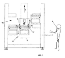
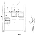
- FIGURES from 6 to 9 represent some operating phases of the installation of FIG. 1;
- FIG. 10 is a plan view of a variant application of the installation of FIG. 1;
- FIG. 11 represents a further variant application of the installation of FIG. 1.
- The accumulator forming installation of the invention is represented in FIG. 1, where it is indicated as a whole by 1, and comprises a plurality of
pallets 2 on/from which the accumulators A to be formed are placed/collected in correspondence with the loading/unloading stations 3 and 4, power supply means 5 and electrolyte feeding means 6 for the accumulators A to be formed. - The invention comprises a
casing 7 provided with a plurality of projecting supports 8 positioned side by side and aligned in vertical direction, suitable for supporting thepallets 2 by placing them one on top of the other, in such a way as to create the same number of formingstations 9 for the accumulators A to be formed, and handling means, indicated as a whole by 10, suitable for moving thepallets 2 among the loading andunloading stations 3 and 4 and the formingstations 9. - In particular, in the example described herein, the
loading station 3 and the unloading station 4 coincide and are defined by the pair of lower projecting supports 11 arranged on the two sides of thecasing 7 and by theplane 12 situated between them. - In each one of said
pallets 2 the power supply means 5 and the electrolyte feeding means 6 are positioned, as shown in detail in FIG. 2, below the ideal line, indicated by 8L, along which eachpallet 2 is suspended from the respective projecting supports 8 and handling means 10. - In this manner special routes shown in FIG. 2 and indicated by P are created, which are free from hindrances and ensure the continuous feeding of the accumulators A, even during the handling phases of the
pallets 2. - As far as the handling means 10 are concerned, they comprise travel means 13, visible in detail in FIG. 3, and lifting means 18, visible in detail in FIG. 1.
- In particular, the travel means 13 comprise first powering means 14 and first
kinematic units 15 provided with coupling means 16 suitable for mating to second coupling means 17 present on eachpallet 2, in order to ensure the coupling and the successive shifting of thepallet 2 along the horizontal direction O, while the lifting means 18 comprise second powering means 19 and secondkinematic units 20 that permit the movement of eachpallet 2 along the vertical direction V. - It is important to consider that the
pallets 2 are vertically spaced from one another of adistance 21 that cannot be shorter than theheight 22 of the accumulators A supported by each pallet. - It is also important to observe that each
pallet 2, as it can be seen in FIG. 3, is provided with sliding means, indicated as a whole by 23, suitable for facilitating its movement towards or away from the loading/unloading stations 3 and 4 and towards or away from each projectingsupport 8 and constituted byidle rollers 24, and said sliding means, according to a variant application of the invention, can be present on theprojecting supports 8 or on the handling means 10 or on both of them. - As to the power supply means represented in detail in FIGURES 4 and 5, where they are indicated as a whole by 5, they comprise a
collector cable 25 integral with eachpallet 2 and connected, by means of a flexible cable 26 visible in FIG. 1, to a continuous power unit not shown in the figure and provided with a plurality ofelectric terminals 27 withremovable connectors 28 for the connection to the respective poles, positive and negative, of each one of the accumulators A to be formed. - The
removable connectors 28 connect the accumulators A to be formed preferably, but not necessarily in series. - As to the electrolyte feeding means 6, also visible in FIGURES 4-5, they comprise two manifolds for the feeding and return of the electrolyte, indicated respectively by 29 and 30, each one integral with each
pallet 2 and connected, through the same number of flexible pipes 31 shown in FIG. 1, to a feed and return unit that is not represented in the figure. - The feed and return unit provides for the forced circulation of the electrolyte inside each accumulator A, as required by the forming and charging process, also preventing the accumulation of hydrogen. It is well known, in fact, that during the forming process hydrogen is developed, which is highly flammable if present in the atmosphere in a percentage exceeding 4%.
- Each
manifold filling elements 32 that can be removably connected to the filling holes of each accumulator to be formed A. - Each
filling element 32 is preferably of the already known type. As to thepallets 2, they comprise asupport surface 35 for the accumulators A to be formed, said support surface being developed longitudinally and being visible in particular in FIG. 3. Said surface is supported at the ends by a substantially U-shapedbearing structure 36, in which the second coupling means 17 are provided and which supports thecollector cable 25 and the twomanifolds - Furthermore, as shown in FIG. 1, the installation is provided with suction means, indicated as a whole by 33, for the gases developed in each accumulator, comprising in particular an
aspirator 37 positioned above thecasing 7. - The suction means is necessary, since it permits the elimination of any toxic vapours that may be inhaled by the operator in charge with the installation. The suction is more effective thanks to the presence of a plurality of
panels 7a positioned on the casing perimeter and surrounding the installation. - An automatic fire fighting system, not represented in the figure, may be placed inside said space, and it should preferably be of the type with chemical extinguisher.
- It must also be observed that either the flexible cable 26 and the flexible pipes 31 are supported by a releasing/retrieving unit, indicated as a whole by 41 in FIG. 1.
- From an operational point of view, the installation is designed so that the accumulators A to be formed coming from the assembly line reach the
loading station 3, for example by means of a conveyor belt. An operator P places them on thepallet 2, connects eachremovable connector 28 to the corresponding poles of each accumulator A and inserts the fillingelement 32 in the corresponding electrolyte filling holes of each accumulator A, thus guaranteeing the supply of power and electrolyte. - Successively the operator P, through a control panel that is not represented in the figure, operates the handling means 10, which first get near the
loading station 3 and then collect thepallet 2 through the mating of the first coupling means 16 and second coupling means 17, as shown in FIG. 7, to convey saidpallet 2 to a free formingstation 9a, as shown in FIGURES 7 and 8. - Once the free forming
station 9a has been reached, the travel means 13 automatically provide for shifting thepallet 2 horizontally and placing it in the free formingstation 9a, as shown in FIG. 9. - The accumulators A to be formed positioned on the respective forming
stations 9 undergo the filling, forming and charging cycle, after which, with a procedure analogue to that described above, but performed in the reverse order, are collected from each forming station and brought to the unloading station 4, where the operator provides for removing them. - In particular, the cycle of the accumulators A to be formed positioned on each forming
station 9 is controlled by an intelligent unit, not represented in the figures, which provides for the coordination of the travel means 13 and lifting means 18 and controls the operation of the suction installation and the capacity of the electrolyte feeding installation and of the power supply installation. - A variant application of the described installation, represented in FIG. 10, where it is indicated as a whole by 100, is differentiated from the previous one by the fact that the handling means do not belong to the
casing 7. - In particular, said handling means 10a are constituted by a trilateral forklift M that makes it possible to collect the accumulators, previously positioned side by side on a
surface 44, and then places them on each forming station defined by thecasings 70. - In a further variant application represented in detail in FIG. 11 and indicated as a whole by 170 the filling
element 32 and eachremovable connector 28 are integral with a bearingelement 45 developed longitudinally and supported at its ends by actuators, comprising for example a pair ofpneumatic jacks 46 fixed to thesupport structure 170. - In particular, each
pneumatic jack 46, controlled by the intelligent control unit, has thecylinder 46a fixed to thesupport structure 170 and therod 46b hinged to thebearing element 45. - From an operational point of view, once the accumulators A to be formed have been positioned on the forming station, the control unit operates the
jacks 46 and moves the bearingelement 45 in a substantially vertical direction, until each fillingelement 32 is connected to each electrolyte filling hole and eachremovable connector 28 is connected to each pole. - Even though the invention has been described with reference to the enclosed drawings, upon implementation changes may be made that are all included in the inventive concepts expressed in the following claims.
Claims (19)
- An accumulator forming installation for filling and charging accumulators (A) (1), the installation including:characterized in that it comprises:a plurality of pallets (2) adapted to support a plurality of accumulators (A) aligned in a side-by-side relationship on said pallet;at least one loading station (3) for loading of said accumulators to said pallets;at least one unloading station (4) for unloading said accumulators (A) from said pallets;power supply means (5) for charging said accumulators (A); andelectrolyte feeding means (6) for feeding electrolyte to said accumulators (A);a casing (7) for filling and charging said accumulators (A), said casing including a plurality of projecting supports (8) positioned in a side-by-side relationship and aligned in a generally vertical orientation such that positioning of said supports in said vertical orientation provides a plurality of forming stations (9), said supporting means further adapted to support said pallets in a substantially horizontal position arranged one on top of the other in said vertical orientation;said casing further including said electrolyte feeding means (6) operatively associated with accumulators (A) for feeding electrolyte to said accumulators (A) aligned on said pallets (2);said power supply means being operatively associated with accumulators when aligned on said pallets; andhandling means (10) for moving said pallets (2) between said loading (3) and unloading stations (4) and said forming stations (9).
- Installation (1) according to claim 1), characterized in that in each of said pallets (2), said power supply means (5) and said electrolyte feeding means (6) are positioned at a point (8L) below that of said projecting supports (8) and said handling means (10).
- Installation (1) according to claim 1), characterized in that said handling means (10) comprise travel means (13) provided with first powering means (14) and first kinematic units (15) provided in turn with first coupling means (16) suitable for mating to second coupling means (17) present on said pallets (2) in order to move said pallets (2) horizontally.
- Installation according to claim 3), characterized in that said handling means (10) comprise lifting means (18) provided with second powering means (10) and second kinematic units (20) to move said pallets (2) in vertical direction.
- Installation (1) according to claim 1), characterized in that said pallets (2) are vertically spaced from one another of a distance (21) that cannot be shorter than the height (22) of the accumulators (A) supported by each of them.
- Installation (1) according to claim 1), characterized in that said pallets (2) are provided with sliding means (23) to make it easier to push said pallets (2) away from/onto said handling means (10), onto/away from said loading (3)/unloading (4) stations and onto/away from said projecting supports (8).
- Installation (1) according to claim 6), characterized in that said handling means (10), said loading(3)/unloading (4) stations and said projecting supports (8) are provided with sliding means (23) to make it easier to push said pallets (2) away from/onto said handling means (10), onto/away from said loading (3)/unloading (4) stations and onto/away from said projecting supports (8).
- Installation (1) according to claim 7), characterized in that said sliding means (23) are constituted by a plane with idle balls (24) or idle rollers.
- Installation (1) according to claim 1), characterized in that said power supply means (5) comprise at least one collector cable (25) integral with each pallet (2), connected to a power unit by means of a flexible pipe (26) and provided with a plurality of electric terminals (27) with removable connectors (28) for the connection to the corresponding poles of each one of said accumulators (A).
- Installation (1) according to claim 9), characterized in that said removable connectors (28) connect said accumulators (A) in series.
- Installation (1) according to claim 9), characterized in that said removable connectors (28) connect said accumulators (A) in parallel.
- Installation (1) according to claim 1), characterized in that the electrolyte feeding means (6) comprise at least one feeding manifold (29) and at least one electrolyte return manifold (30), each one integral with each pallet (2), and connected to a releasing/retrieving unit (41) by means of the same number of flexible pipes (31), said manifolds (29, 30) being connected to at least one filling element (32) removably connected to one or more filling holes of each accumulator (A).
- Installation (1) according to claim 1), characterized in that each one of said pallets (2) comprises at least one support surface (35), with mainly longitudinal development, for said accumulators (A) to be formed, and at least one bearing structure (36) developed longitudinally with respect to said support surface (35) to support said electric terminals and said feed (29) and return (30) manifolds.
- Installation (1) according to claim 13), characterized in that said bearing structure comprises actuators for the automatic connection of said electric terminals to said accumulators.
- Installation (1) according to claim 1), characterized in that it comprises suction means (33) for the elimination of the gases developed in each one of said accumulators (A) during the charging phase.
- Installation (1) according to claim 15), characterized in that said suction means (33) comprise at least one aspirator (37) positioned above said casing (7).
- Installation (1) according to claim 1), characterized in that each one of said electrical cables, of said feed and return pipes and of said flexible pipes is supported by a corresponding releasing/retrieving unit (41).
- Installation (1) according to claim 1), characterized in that it comprises a plurality of panels (7a) arranged along the perimeter of said casing (7) to delimit the volume of said installation (1).
- Installation (1) according to claim 1), characterized in that it is provided with a fire fighting system.
Priority Applications (1)
| Application Number | Priority Date | Filing Date | Title |
|---|---|---|---|
| SI200030282T SI1236238T1 (en) | 1999-11-19 | 2000-11-14 | Accumulator forming installation |
Applications Claiming Priority (3)
| Application Number | Priority Date | Filing Date | Title |
|---|---|---|---|
| IT1999VI000235A IT1307517B1 (en) | 1999-11-19 | 1999-11-19 | ACCUMULATOR TRAINING SYSTEM |
| ITVI990235 | 1999-11-19 | ||
| PCT/EP2000/011226 WO2001037363A1 (en) | 1999-11-19 | 2000-11-14 | Accumulator forming installation |
Publications (2)
| Publication Number | Publication Date |
|---|---|
| EP1236238A1 EP1236238A1 (en) | 2002-09-04 |
| EP1236238B1 true EP1236238B1 (en) | 2003-10-01 |
Family
ID=11427210
Family Applications (1)
| Application Number | Title | Priority Date | Filing Date |
|---|---|---|---|
| EP00985021A Expired - Lifetime EP1236238B1 (en) | 1999-11-19 | 2000-11-14 | Accumulator forming installation |
Country Status (16)
| Country | Link |
|---|---|
| US (1) | US6782605B1 (en) |
| EP (1) | EP1236238B1 (en) |
| JP (1) | JP3889624B2 (en) |
| KR (1) | KR100451417B1 (en) |
| CN (1) | CN1211876C (en) |
| AT (1) | ATE251346T1 (en) |
| AU (1) | AU2158201A (en) |
| BR (1) | BR0015679A (en) |
| CA (1) | CA2392005C (en) |
| DE (1) | DE60005707T2 (en) |
| ES (1) | ES2208449T3 (en) |
| IT (1) | IT1307517B1 (en) |
| PT (1) | PT1236238E (en) |
| RU (1) | RU2237319C2 (en) |
| TR (1) | TR200201318T2 (en) |
| WO (1) | WO2001037363A1 (en) |
Cited By (1)
| Publication number | Priority date | Publication date | Assignee | Title |
|---|---|---|---|---|
| EP3159960A1 (en) * | 2015-10-19 | 2017-04-26 | Andreas Christian Bäumler | Device for cooling and charging batteries on pallets |
Families Citing this family (25)
| Publication number | Priority date | Publication date | Assignee | Title |
|---|---|---|---|---|
| RU2250539C2 (en) * | 2002-07-09 | 2005-04-20 | Виктор Александрович Дзензерский | Device for assembling lead cells using forced control of electrolyte circulation into storage batteries |
| ITVI20030171A1 (en) * | 2003-09-11 | 2005-03-12 | Franco Stocchiero | DISTRIBUTOR FOR THE CIRCULATION OF THE ACID IN A PLANT |
| ITVI20030170A1 (en) * | 2003-09-11 | 2005-03-12 | Franco Stocchiero | TREATMENT PLAN FOR BATTERY FORMATION SYSTEM |
| US20120052342A1 (en) * | 2010-08-24 | 2012-03-01 | Delta Electronics, Inc. | Energy storage chambers with flexible packages, devices and systems using the same, and method for fabricating the same |
| KR101278506B1 (en) * | 2011-04-25 | 2013-07-02 | 주식회사 엘지화학 | Rack system of battery module for energy storage |
| GB2491601A (en) * | 2011-06-07 | 2012-12-12 | Leclancha S A | Drying process for cost effective production of Li-accumulators |
| WO2014022445A1 (en) * | 2012-08-01 | 2014-02-06 | Enerdel, Inc. | Modular energy storage system |
| CN103107370A (en) * | 2012-11-11 | 2013-05-15 | 广西天鹅蓄电池有限责任公司 | Storage battery formation device |
| CN103811820A (en) * | 2014-01-20 | 2014-05-21 | 超威电源有限公司 | Battery formation assembly line as well as operation technology for battery formation |
| CN103943890B (en) * | 2014-03-05 | 2016-04-13 | 超威电源有限公司 | Be internalized into storage battery manually to reach the standard grade servicing unit |
| WO2017065710A1 (en) * | 2015-10-12 | 2017-04-20 | Zesar Kalipçilik Sanayi̇ Ve Ti̇caret Ltd. Şti̇. | Vertical battery charging station with acid circulation |
| DE102017203957A1 (en) * | 2017-03-10 | 2018-09-13 | Thyssenkrupp Ag | Formation plant and method for delivery to a formation plant |
| CN110350247B (en) * | 2018-04-03 | 2021-08-20 | 深圳市瑞能实业股份有限公司 | Battery composition container |
| CN109167114B (en) * | 2018-08-28 | 2020-07-03 | 陕西中丰新能源有限公司 | Method for forming four large-capacity square batteries in series connection |
| CN109546247A (en) * | 2018-11-22 | 2019-03-29 | 浙江杭可科技股份有限公司 | A kind of column lithium ion battery component capacitive equipment |
| KR102487835B1 (en) | 2019-01-16 | 2023-01-12 | 주식회사 엘지에너지솔루션 | Charging method for decreasing charging time |
| CN111584962B (en) * | 2020-05-07 | 2021-03-30 | 深圳市泰颐通科技有限公司 | Hot-pressing soft-package lithium ion battery formation equipment |
| KR102509244B1 (en) * | 2022-09-02 | 2023-03-14 | (주)그린파워 | Device for Charging and Discharging of Battery Cell |
| IT202300026184A1 (en) * | 2023-12-06 | 2025-06-06 | System Ceram Spa | METHOD AND APPARATUS FOR THE FORMATION OF ELECTROCHEMICAL CELLS FOR THE PRODUCTION OF BATTERIES |
| IT202300026139A1 (en) * | 2023-12-06 | 2025-06-06 | System Ceramics S P A | BATTERY CELL FORMATION PLANT |
| IT202300026178A1 (en) * | 2023-12-06 | 2025-06-06 | System Ceram Spa | METHOD OF FORMING ELECTROCHEMICAL CELLS FOR BATTERY PRODUCTION |
| IT202300026190A1 (en) * | 2023-12-06 | 2025-06-06 | System Ceram Spa | METHOD AND APPARATUS FOR THE FORMATION OF ELECTROCHEMICAL CELLS FOR THE PRODUCTION OF BATTERIES |
| IT202300026079A1 (en) * | 2023-12-06 | 2025-06-06 | System Ceramics S P A | AUTOMATIC WAREHOUSE FOR THE FORMATION OF ELECTROCHEMICAL CELLS |
| WO2025120565A1 (en) * | 2023-12-06 | 2025-06-12 | System Ceramics Spa | Method and apparatus for forming electrochemical cells for battery production |
| IT202400013921A1 (en) * | 2024-06-18 | 2025-12-18 | System Ceramics S P A | WAREHOUSE FOR THE FORMATION OF ELECTROCHEMICAL CELLS FOR BATTERY PRODUCTION |
Family Cites Families (9)
| Publication number | Priority date | Publication date | Assignee | Title |
|---|---|---|---|---|
| US3816898A (en) * | 1971-12-13 | 1974-06-18 | Tudor Ab | Apparatus for arranging and soldering together electrode sets for lead accumulators |
| US3908738A (en) * | 1974-01-21 | 1975-09-30 | Gould Inc | Method of positive displacement bonding of battery components |
| FI83001C (en) * | 1988-04-14 | 1991-05-10 | Neste Oy | Device for tethering and forming accumulators |
| US5025551A (en) * | 1990-01-12 | 1991-06-25 | Sealed Energy Systems, Inc. | Method for the assembly of lead-acid batteries and associated apparatus |
| US5370711A (en) * | 1993-07-21 | 1994-12-06 | Ev Energy Systems, Inc. | Method for making an electrical energy storage device |
| RU2054354C1 (en) * | 1995-02-13 | 1996-02-20 | Сдвижков Николай Тихонович | Line for brick production |
| DE19544050A1 (en) * | 1995-11-25 | 1997-05-28 | Emmerich Christoph Gmbh Co Kg | Process for the production of prismatic alkaline accumulator cells |
| JPH10106614A (en) * | 1996-09-25 | 1998-04-24 | Matsushita Electric Ind Co Ltd | Air-cooled battery case formation method and apparatus |
| US7097936B2 (en) * | 2001-08-27 | 2006-08-29 | Enerdel, Inc. | Battery constructed with extracted bicells stacked on shuttled pallet |
-
1999
- 1999-11-19 IT IT1999VI000235A patent/IT1307517B1/en active
-
2000
- 2000-11-14 AT AT00985021T patent/ATE251346T1/en active
- 2000-11-14 KR KR10-2002-7005213A patent/KR100451417B1/en not_active Expired - Fee Related
- 2000-11-14 CA CA002392005A patent/CA2392005C/en not_active Expired - Fee Related
- 2000-11-14 CN CNB008158800A patent/CN1211876C/en not_active Expired - Fee Related
- 2000-11-14 WO PCT/EP2000/011226 patent/WO2001037363A1/en not_active Ceased
- 2000-11-14 US US10/110,529 patent/US6782605B1/en not_active Expired - Fee Related
- 2000-11-14 PT PT00985021T patent/PT1236238E/en unknown
- 2000-11-14 TR TR2002/01318T patent/TR200201318T2/en unknown
- 2000-11-14 BR BR0015679-5A patent/BR0015679A/en not_active Application Discontinuation
- 2000-11-14 EP EP00985021A patent/EP1236238B1/en not_active Expired - Lifetime
- 2000-11-14 DE DE60005707T patent/DE60005707T2/en not_active Expired - Lifetime
- 2000-11-14 ES ES00985021T patent/ES2208449T3/en not_active Expired - Lifetime
- 2000-11-14 JP JP2001537816A patent/JP3889624B2/en not_active Expired - Fee Related
- 2000-11-14 AU AU21582/01A patent/AU2158201A/en not_active Abandoned
- 2000-11-14 RU RU2002116372/09A patent/RU2237319C2/en not_active IP Right Cessation
Cited By (1)
| Publication number | Priority date | Publication date | Assignee | Title |
|---|---|---|---|---|
| EP3159960A1 (en) * | 2015-10-19 | 2017-04-26 | Andreas Christian Bäumler | Device for cooling and charging batteries on pallets |
Also Published As
| Publication number | Publication date |
|---|---|
| PT1236238E (en) | 2004-02-27 |
| JP3889624B2 (en) | 2007-03-07 |
| KR20020043240A (en) | 2002-06-08 |
| DE60005707D1 (en) | 2003-11-06 |
| ATE251346T1 (en) | 2003-10-15 |
| TR200201318T2 (en) | 2002-09-23 |
| RU2002116372A (en) | 2004-01-27 |
| BR0015679A (en) | 2002-08-06 |
| AU2158201A (en) | 2001-05-30 |
| RU2237319C2 (en) | 2004-09-27 |
| KR100451417B1 (en) | 2004-10-07 |
| DE60005707T2 (en) | 2004-08-05 |
| CN1211876C (en) | 2005-07-20 |
| WO2001037363A1 (en) | 2001-05-25 |
| US6782605B1 (en) | 2004-08-31 |
| ES2208449T3 (en) | 2004-06-16 |
| EP1236238A1 (en) | 2002-09-04 |
| IT1307517B1 (en) | 2001-11-06 |
| CN1391707A (en) | 2003-01-15 |
| ITVI990235A1 (en) | 2001-05-19 |
| CA2392005A1 (en) | 2001-05-25 |
| JP2003514368A (en) | 2003-04-15 |
| CA2392005C (en) | 2006-03-28 |
Similar Documents
| Publication | Publication Date | Title |
|---|---|---|
| US6782605B1 (en) | Accumulator forming installation | |
| DE4411842A1 (en) | Battery charging station | |
| CN116936905A (en) | Battery package automated inspection equipment production line | |
| CN115832482A (en) | Novel battery discharging equipment and process | |
| CN111113028B (en) | Assembly line for modular switch cabinet | |
| CN218810300U (en) | Side-mounted lithium battery electrolyte filling system | |
| US3776399A (en) | Automatic warehousing system | |
| CN103522054B (en) | EMUs journal box spring press-loading apparatus and method | |
| CN108584381A (en) | Transmission system is disassembled for the battery pack in waste and old power battery intelligence disassembly system | |
| CN210272563U (en) | A fully automated machine suitable for batteries | |
| CN210029048U (en) | Feeding device and production system | |
| CN219669889U (en) | Household photovoltaic equipment overhead hoist | |
| CN216944668U (en) | Automatic copper bar storehouse discharge system | |
| CN207618049U (en) | A kind of backing plate automatic packing device | |
| CN212100914U (en) | Stator-rotor iron core automatic discharging and collecting unit | |
| CN113471611A (en) | Device for conveying storage battery into storage battery cabinet | |
| CN111285106A (en) | Stator-rotor iron core automatic discharging and collecting unit | |
| CN114604558B (en) | Three-dimensional storage system for battery polar plates and control method | |
| CN108511835B (en) | A battery pack distribution and transmission system used in an intelligent dismantling system for used power batteries | |
| CN220641705U (en) | Automatic frame and frame stacking mechanism of robot | |
| CN207089036U (en) | A kind of container-type movable charging system | |
| CN113895972B (en) | Automatic general inspection machine sheet separator capable of preventing product from tilting | |
| CN211625999U (en) | In-line type straight-in straight-out automatic vacuum drying equipment | |
| CN220467334U (en) | Power distribution cabinet transfer robot | |
| CN220525886U (en) | A kind of testing equipment for capacitor modules |
Legal Events
| Date | Code | Title | Description |
|---|---|---|---|
| PUAI | Public reference made under article 153(3) epc to a published international application that has entered the european phase |
Free format text: ORIGINAL CODE: 0009012 |
|
| 17P | Request for examination filed |
Effective date: 20020619 |
|
| AK | Designated contracting states |
Kind code of ref document: A1 Designated state(s): AT BE CH CY DE DK ES FI FR GB GR IE IT LI LU MC NL PT SE TR |
|
| AX | Request for extension of the european patent |
Free format text: AL;LT;LV;MK;RO PAYMENT 20020619;SI PAYMENT 20020619 |
|
| GRAH | Despatch of communication of intention to grant a patent |
Free format text: ORIGINAL CODE: EPIDOS IGRA |
|
| GRAS | Grant fee paid |
Free format text: ORIGINAL CODE: EPIDOSNIGR3 |
|
| GRAA | (expected) grant |
Free format text: ORIGINAL CODE: 0009210 |
|
| AK | Designated contracting states |
Kind code of ref document: B1 Designated state(s): AT BE CH CY DE DK ES FI FR GB GR IE IT LI LU MC NL PT SE TR |
|
| AX | Request for extension of the european patent |
Extension state: RO SI |
|
| PG25 | Lapsed in a contracting state [announced via postgrant information from national office to epo] |
Ref country code: BE Free format text: LAPSE BECAUSE OF FAILURE TO SUBMIT A TRANSLATION OF THE DESCRIPTION OR TO PAY THE FEE WITHIN THE PRESCRIBED TIME-LIMIT Effective date: 20031001 Ref country code: TR Free format text: LAPSE BECAUSE OF FAILURE TO SUBMIT A TRANSLATION OF THE DESCRIPTION OR TO PAY THE FEE WITHIN THE PRESCRIBED TIME-LIMIT Effective date: 20031001 Ref country code: FI Free format text: LAPSE BECAUSE OF FAILURE TO SUBMIT A TRANSLATION OF THE DESCRIPTION OR TO PAY THE FEE WITHIN THE PRESCRIBED TIME-LIMIT Effective date: 20031001 |
|
| REG | Reference to a national code |
Ref country code: GB Ref legal event code: FG4D |
|
| REG | Reference to a national code |
Ref country code: CH Ref legal event code: EP |
|
| REG | Reference to a national code |
Ref country code: IE Ref legal event code: FG4D |
|
| REF | Corresponds to: |
Ref document number: 60005707 Country of ref document: DE Date of ref document: 20031106 Kind code of ref document: P |
|
| PG25 | Lapsed in a contracting state [announced via postgrant information from national office to epo] |
Ref country code: IE Free format text: LAPSE BECAUSE OF NON-PAYMENT OF DUE FEES Effective date: 20031114 Ref country code: CY Free format text: LAPSE BECAUSE OF FAILURE TO SUBMIT A TRANSLATION OF THE DESCRIPTION OR TO PAY THE FEE WITHIN THE PRESCRIBED TIME-LIMIT Effective date: 20031114 |
|
| PG25 | Lapsed in a contracting state [announced via postgrant information from national office to epo] |
Ref country code: MC Free format text: LAPSE BECAUSE OF NON-PAYMENT OF DUE FEES Effective date: 20031130 |
|
| PG25 | Lapsed in a contracting state [announced via postgrant information from national office to epo] |
Ref country code: DK Free format text: LAPSE BECAUSE OF FAILURE TO SUBMIT A TRANSLATION OF THE DESCRIPTION OR TO PAY THE FEE WITHIN THE PRESCRIBED TIME-LIMIT Effective date: 20040101 |
|
| REG | Reference to a national code |
Ref country code: SE Ref legal event code: TRGR |
|
| REG | Reference to a national code |
Ref country code: CH Ref legal event code: NV Representative=s name: KIRKER & CIE SA |
|
| REG | Reference to a national code |
Ref country code: GR Ref legal event code: EP Ref document number: 20030405217 Country of ref document: GR |
|
| LTIE | Lt: invalidation of european patent or patent extension |
Effective date: 20031001 |
|
| REG | Reference to a national code |
Ref country code: ES Ref legal event code: FG2A Ref document number: 2208449 Country of ref document: ES Kind code of ref document: T3 |
|
| ET | Fr: translation filed | ||
| PLBE | No opposition filed within time limit |
Free format text: ORIGINAL CODE: 0009261 |
|
| STAA | Information on the status of an ep patent application or granted ep patent |
Free format text: STATUS: NO OPPOSITION FILED WITHIN TIME LIMIT |
|
| REG | Reference to a national code |
Ref country code: IE Ref legal event code: MM4A |
|
| 26N | No opposition filed |
Effective date: 20040702 |
|
| REG | Reference to a national code |
Ref country code: SI Ref legal event code: IF |
|
| PGFP | Annual fee paid to national office [announced via postgrant information from national office to epo] |
Ref country code: GR Payment date: 20051026 Year of fee payment: 6 |
|
| PGFP | Annual fee paid to national office [announced via postgrant information from national office to epo] |
Ref country code: NL Payment date: 20051106 Year of fee payment: 6 |
|
| PGFP | Annual fee paid to national office [announced via postgrant information from national office to epo] |
Ref country code: SE Payment date: 20051107 Year of fee payment: 6 |
|
| PGFP | Annual fee paid to national office [announced via postgrant information from national office to epo] |
Ref country code: PT Payment date: 20051114 Year of fee payment: 6 |
|
| PGFP | Annual fee paid to national office [announced via postgrant information from national office to epo] |
Ref country code: CH Payment date: 20051115 Year of fee payment: 6 |
|
| PGFP | Annual fee paid to national office [announced via postgrant information from national office to epo] |
Ref country code: LU Payment date: 20051125 Year of fee payment: 6 |
|
| PGFP | Annual fee paid to national office [announced via postgrant information from national office to epo] |
Ref country code: BE Payment date: 20060123 Year of fee payment: 6 |
|
| PG25 | Lapsed in a contracting state [announced via postgrant information from national office to epo] |
Ref country code: SE Free format text: LAPSE BECAUSE OF NON-PAYMENT OF DUE FEES Effective date: 20061115 |
|
| PG25 | Lapsed in a contracting state [announced via postgrant information from national office to epo] |
Ref country code: CH Free format text: LAPSE BECAUSE OF NON-PAYMENT OF DUE FEES Effective date: 20061130 Ref country code: LI Free format text: LAPSE BECAUSE OF NON-PAYMENT OF DUE FEES Effective date: 20061130 |
|
| PG25 | Lapsed in a contracting state [announced via postgrant information from national office to epo] |
Ref country code: PT Free format text: LAPSE BECAUSE OF NON-PAYMENT OF DUE FEES Effective date: 20070514 |
|
| REG | Reference to a national code |
Ref country code: PT Ref legal event code: MM4A Free format text: LAPSE DUE TO NON-PAYMENT OF FEES Effective date: 20070514 |
|
| PG25 | Lapsed in a contracting state [announced via postgrant information from national office to epo] |
Ref country code: NL Free format text: LAPSE BECAUSE OF NON-PAYMENT OF DUE FEES Effective date: 20070601 |
|
| REG | Reference to a national code |
Ref country code: CH Ref legal event code: PL |
|
| EUG | Se: european patent has lapsed | ||
| NLV4 | Nl: lapsed or anulled due to non-payment of the annual fee |
Effective date: 20070601 |
|
| BERE | Be: lapsed |
Owner name: *STOCCHIERO FRANCO Effective date: 20061130 |
|
| PG25 | Lapsed in a contracting state [announced via postgrant information from national office to epo] |
Ref country code: LU Free format text: LAPSE BECAUSE OF NON-PAYMENT OF DUE FEES Effective date: 20061114 |
|
| PG25 | Lapsed in a contracting state [announced via postgrant information from national office to epo] |
Ref country code: GR Free format text: LAPSE BECAUSE OF NON-PAYMENT OF DUE FEES Effective date: 20070604 |
|
| PG25 | Lapsed in a contracting state [announced via postgrant information from national office to epo] |
Ref country code: IT Free format text: LAPSE BECAUSE OF NON-PAYMENT OF DUE FEES Effective date: 20081114 |
|
| PGFP | Annual fee paid to national office [announced via postgrant information from national office to epo] |
Ref country code: FR Payment date: 20101130 Year of fee payment: 11 Ref country code: AT Payment date: 20101112 Year of fee payment: 11 |
|
| PGFP | Annual fee paid to national office [announced via postgrant information from national office to epo] |
Ref country code: DE Payment date: 20101119 Year of fee payment: 11 |
|
| PGFP | Annual fee paid to national office [announced via postgrant information from national office to epo] |
Ref country code: GB Payment date: 20101118 Year of fee payment: 11 |
|
| PGFP | Annual fee paid to national office [announced via postgrant information from national office to epo] |
Ref country code: ES Payment date: 20101124 Year of fee payment: 11 |
|
| PGFP | Annual fee paid to national office [announced via postgrant information from national office to epo] |
Ref country code: IT Payment date: 20101104 Year of fee payment: 11 |
|
| PGRI | Patent reinstated in contracting state [announced from national office to epo] |
Ref country code: IT Effective date: 20110616 |
|
| GBPC | Gb: european patent ceased through non-payment of renewal fee |
Effective date: 20111114 |
|
| REG | Reference to a national code |
Ref country code: SI Ref legal event code: KO00 Effective date: 20120627 |
|
| REG | Reference to a national code |
Ref country code: FR Ref legal event code: ST Effective date: 20120731 |
|
| PG25 | Lapsed in a contracting state [announced via postgrant information from national office to epo] |
Ref country code: IT Free format text: LAPSE BECAUSE OF NON-PAYMENT OF DUE FEES Effective date: 20111114 |
|
| REG | Reference to a national code |
Ref country code: DE Ref legal event code: R119 Ref document number: 60005707 Country of ref document: DE Effective date: 20120601 |
|
| PG25 | Lapsed in a contracting state [announced via postgrant information from national office to epo] |
Ref country code: GB Free format text: LAPSE BECAUSE OF NON-PAYMENT OF DUE FEES Effective date: 20111114 |
|
| REG | Reference to a national code |
Ref country code: AT Ref legal event code: MM01 Ref document number: 251346 Country of ref document: AT Kind code of ref document: T Effective date: 20111114 |
|
| PG25 | Lapsed in a contracting state [announced via postgrant information from national office to epo] |
Ref country code: FR Free format text: LAPSE BECAUSE OF NON-PAYMENT OF DUE FEES Effective date: 20111130 |
|
| PG25 | Lapsed in a contracting state [announced via postgrant information from national office to epo] |
Ref country code: AT Free format text: LAPSE BECAUSE OF NON-PAYMENT OF DUE FEES Effective date: 20111114 |
|
| REG | Reference to a national code |
Ref country code: ES Ref legal event code: FD2A Effective date: 20130605 |
|
| PG25 | Lapsed in a contracting state [announced via postgrant information from national office to epo] |
Ref country code: DE Free format text: LAPSE BECAUSE OF NON-PAYMENT OF DUE FEES Effective date: 20120601 |
|
| PG25 | Lapsed in a contracting state [announced via postgrant information from national office to epo] |
Ref country code: ES Free format text: LAPSE BECAUSE OF NON-PAYMENT OF DUE FEES Effective date: 20111115 |