EP1235703B1 - Anti-roping latch plate - Google Patents
Anti-roping latch plate Download PDFInfo
- Publication number
- EP1235703B1 EP1235703B1 EP00954107A EP00954107A EP1235703B1 EP 1235703 B1 EP1235703 B1 EP 1235703B1 EP 00954107 A EP00954107 A EP 00954107A EP 00954107 A EP00954107 A EP 00954107A EP 1235703 B1 EP1235703 B1 EP 1235703B1
- Authority
- EP
- European Patent Office
- Prior art keywords
- seat belt
- tab
- latch plate
- load bearing
- bearing plate
- Prior art date
- Legal status (The legal status is an assumption and is not a legal conclusion. Google has not performed a legal analysis and makes no representation as to the accuracy of the status listed.)
- Expired - Lifetime
Links
Images


Classifications
-
- A—HUMAN NECESSITIES
- A44—HABERDASHERY; JEWELLERY
- A44B—BUTTONS, PINS, BUCKLES, SLIDE FASTENERS, OR THE LIKE
- A44B11/00—Buckles; Similar fasteners for interconnecting straps or the like, e.g. for safety belts
- A44B11/25—Buckles; Similar fasteners for interconnecting straps or the like, e.g. for safety belts with two or more separable parts
- A44B11/2503—Safety buckles
- A44B11/2546—Details
- A44B11/2561—Tongue elements
-
- A—HUMAN NECESSITIES
- A44—HABERDASHERY; JEWELLERY
- A44B—BUTTONS, PINS, BUCKLES, SLIDE FASTENERS, OR THE LIKE
- A44B11/00—Buckles; Similar fasteners for interconnecting straps or the like, e.g. for safety belts
- A44B11/25—Buckles; Similar fasteners for interconnecting straps or the like, e.g. for safety belts with two or more separable parts
- A44B11/2503—Safety buckles
- A44B11/2546—Details
- A44B11/2553—Attachment of buckle to strap
-
- B—PERFORMING OPERATIONS; TRANSPORTING
- B60—VEHICLES IN GENERAL
- B60R—VEHICLES, VEHICLE FITTINGS, OR VEHICLE PARTS, NOT OTHERWISE PROVIDED FOR
- B60R22/00—Safety belts or body harnesses in vehicles
- B60R22/18—Anchoring devices
-
- B—PERFORMING OPERATIONS; TRANSPORTING
- B60—VEHICLES IN GENERAL
- B60R—VEHICLES, VEHICLE FITTINGS, OR VEHICLE PARTS, NOT OTHERWISE PROVIDED FOR
- B60R22/00—Safety belts or body harnesses in vehicles
- B60R22/30—Coupling devices other than buckles, including length-adjusting fittings or anti-slip devices
-
- B—PERFORMING OPERATIONS; TRANSPORTING
- B60—VEHICLES IN GENERAL
- B60R—VEHICLES, VEHICLE FITTINGS, OR VEHICLE PARTS, NOT OTHERWISE PROVIDED FOR
- B60R22/00—Safety belts or body harnesses in vehicles
- B60R22/18—Anchoring devices
- B60R2022/1812—Connections between seat belt and buckle tongue
-
- Y—GENERAL TAGGING OF NEW TECHNOLOGICAL DEVELOPMENTS; GENERAL TAGGING OF CROSS-SECTIONAL TECHNOLOGIES SPANNING OVER SEVERAL SECTIONS OF THE IPC; TECHNICAL SUBJECTS COVERED BY FORMER USPC CROSS-REFERENCE ART COLLECTIONS [XRACs] AND DIGESTS
- Y10—TECHNICAL SUBJECTS COVERED BY FORMER USPC
- Y10T—TECHNICAL SUBJECTS COVERED BY FORMER US CLASSIFICATION
- Y10T24/00—Buckles, buttons, clasps, etc.
- Y10T24/40—Buckles
- Y10T24/4088—One-piece
-
- Y—GENERAL TAGGING OF NEW TECHNOLOGICAL DEVELOPMENTS; GENERAL TAGGING OF CROSS-SECTIONAL TECHNOLOGIES SPANNING OVER SEVERAL SECTIONS OF THE IPC; TECHNICAL SUBJECTS COVERED BY FORMER USPC CROSS-REFERENCE ART COLLECTIONS [XRACs] AND DIGESTS
- Y10—TECHNICAL SUBJECTS COVERED BY FORMER USPC
- Y10T—TECHNICAL SUBJECTS COVERED BY FORMER US CLASSIFICATION
- Y10T24/00—Buckles, buttons, clasps, etc.
- Y10T24/45—Separable-fastener or required component thereof [e.g., projection and cavity to complete interlock]
- Y10T24/45225—Separable-fastener or required component thereof [e.g., projection and cavity to complete interlock] including member having distinct formations and mating member selectively interlocking therewith
- Y10T24/45602—Receiving member includes either movable connection between interlocking components or variable configuration cavity
- Y10T24/45623—Receiving member includes either movable connection between interlocking components or variable configuration cavity and operator therefor
Definitions
- the invention relates to an anti-roping latch plate for use with a seat belt buckle.
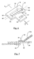
- FIGS. 1 and 2 show a prior art latch plate 20.
- the latch plate comprises a tongue portion 22 having a first latching feature 24, such as an opening, which engages a locking mechanism of a seat belt buckle.
- the latch plate further includes a rear or plate portion 26 having an oblong opening 28 of sufficient size to permit the seat belt 30 to extend therethrough.
- the rearward end 26a of plate 26 is often bent away from the plane of the tongue as illustrated in FIG. 2.
- the latch plate 20 in the vicinity of opening 28 may be covered by a low-friction plastic coating.
- US 4,023,826 concerns a latch plate provided with a slotted opening through which slides a seat belt.
- the opening is covered with a resilient molding to reduce frictional resistance of the belt.
- Resilient projections integrally formed with the molding, extend from one edge of the opening to partially intercept the belt. Depending on the direction of the belt movement, resilient projections bend to reduce or to improve the opening width, so to reduce the seat belt roping or undesired pressure on the passenger.
- US 5,222,278 provides a tongue assembly to block the movement of a seat belt through the tongue itself, in particular when securing a child seat.
- the tongue has several openings for receiving the seat belt, which allow the user to set the seat belt on the tongue through three different paths.
- the seat belt roping is lessened by the latch place set forch in appended Claim 1.
- a latch plate for use with a seat belt and seat belt buckle, comprising: a metal load-bearing plate including a tongue for engaging a locking feature of the seat belt buckle, the load-bearing plate also defining a belt receiving opening located between first and second generally parallel surfaces, the first and second parallel surfaces defining a channel to guide the seat belt as it exits the belt receiving opening.
- FIGS. 3 and 4 illustrate a load bearing plate 52 that is the major component of a latch plate 50.
- the load bearing plate includes a first locking feature 54 such as an opening, which engages a latch mechanism 57 of a buckle 56 shown in FIG. 14.
- FIG. 14 shows the buckle with a rotatable latch mechanism that engages the latch plate 50 in a locking manner.
- the opening or locking feature 54 in the load bearing plate 52 is formed within a tongue 58 portion of the load bearing plate.
- the load-bearing plate in a rearward, second portion 60 thereof, includes an integrally formed tab 62.
- the tab is formed by stamping or otherwise forming a narrow U-shaped slot 64 in the load bearing plate.
- the load bearing plate includes a first surface 70 that is positioned forward of the slot. In the first preferred embodiment of the invention this first surface is flat.
- the tab 62 is rotated upwardly as illustrated in FIGS. 5 and 6.
- the rear laterally extending edge 72 of the first surface and the forward edge 74 of the tab are more clearly visible in FIG. 6.
- the forward edge 74 is positioned apart from edge 72 defining a channel 80 therebetween.
- the load bearing plate 52 is bent (see FIGS. 7 and 8) about bend line 82 thereby positioning a rear portion 52a of load bearing plate at an angle relative to the tongue 58. This rotation of the load bearing plate moves the forward edge 74 forwardly closer to the tongue.
- the forward edge of the tab will be moved in line with the rearward edge 72 or be positioned slightly forward of the rearward edge to overlay the first surface 70.
- the resulting configuration is shown in FIG. 8.
- the tab 62 is preferably parallel to the first surface, as can also be seen in FIG. 8a.
- FIG. 8 shows the seat belt 30 in phantom line extending through the latch plate 50 and more particularly extending through the channel 80.
- the seat belt 30 is now guided between two parallel walls, the first formed by the first surface 70 and the second formed by the lower surface 62a of the tab 62.
- the roping, i.e., twisting, curling, etc. of the seat belt is now at a minimum because of the close spacing of the channel to the seat belt and its parallel construction.
- These walls are preferably parallel but can diverge + or - 10 degrees from parallel.
- latch plates 50 of FIG. 8 is fully functional; however, latch plates typically include a low-friction elastomeric coating disposed on various parts of a metal load-bearing plate to protect the seat belt 30.
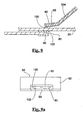
- FIG. 7 shows this coating 90 disposed on the first surface and about edge 72 as well as about rearward portion 52a of the load bearing plate 52.
- FIG. 7 shows the seat belt fitted through channel 80, which in this case is defined by the spacing between the adjacent upper and lower layers of the coating material 90.
- the rear portion 52a extends outwardly from the tongue 58. If this alternate configuration is desirable, the rear portion 52a is again bent about a second bend line 80a, which places the rearmost portion 53 (shown in phantom line in FIG. 8) of the load bearing plate 52 in an orientation generally parallel to that of the tongue. This configuration is also shown in FIG. 8b.
- FIGS. 9 and 9a and FIGS. 10-12 show two additional preferred embodiments of the invention.
- the channel 80 in the earlier embodiment is formed by two flat surfaces 62a, 70, that are coated with a thin layer of plastic material.
- the channel 80 includes a plurality of separated projections.
- FIG. 9 is identical to FIG. 7 with the exception that the plastic coating on the surfaces 62a and 70 is molded to provide a plurality of respective projections 100, 102.
- FIG. 9a is a front view of the latch plate, without the seat belt therein, and shows the relationship between the alternating projections on each of the above surfaces.
- the projections 102 can for example be circular and/or oblong.
- the first surface 70 can be flat. However, in the following embodiment, one or more projections 100 are provided on the first surface. Alternatively, or in combination with the projections, another plurality of projections 102 are also located on the undersurface 62a of the tab.
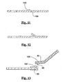
- FIG. 10 is a plan view of the load-bearing plate 52 illustrating a plurality of hemispherically-shaped projections 100 on the first surface 70 and, for the purpose of illustration, oblong-shaped projections 102 on the tab 62. These projections can easily be formed during the stamping process during which the latch plate 50 is formed.
- FIG. 11 is a cross-sectional view taken through section line 11-11 of FIG.
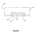
- FIG. 13 shows the coating material 90, which now also covers the projections 100, 102.
- FIG. 13a is a front plan view of this alternate latch plate showing the relationship of the projections, as well as the channel 80 through which the seat belt 30 is received.
- FIG. 15 shows a typical three-point seat belt system 150.
- the system 150 comprises a seat belt retractor 160 of known variety. Extending from the retractor is the seat belt, which is divided into a shoulder belt portion 30a and a lap belt portion 30b.
- the latch plate 50 of the present invention essentially divides the seat belt 30 into the shoulder belt and lap belt portions.
- the remote end of the lap belt is secured, such as to the floor, by an anchor 162.
- the buckle 56 is similarly secured by another anchor 162.
- the seat belt is also threaded through a web guide or D-ring 164.
- the retractor 160 When the latch plate 50 is detached from the buckle 56 the retractor 160 will rewind the seat belt 30 onto a spool (not shown) of the retractor.
- the lap belt portion 30b will be vertically oriented and extend downwardly from the web guide.
- the web guide is also vertical and is shown in this configuration in phantom line.
- the latch plate 50 will fall into one of two categories of latch plates, that is a free-sliding latch plate or a free-falling latch plate. If the channel 80 is narrow, as in the free-sliding latch plate, the seat belt will generate a low level of friction on the latch plate such that upon retraction of the seat belt into the retractor the unbuckled latch plate will be carried with the seat belt to its stowed position (shown in phantom line in FIG. 15). Quite often the latch plate will be carried up to the web guide and as the retractor continues to retract, the seat belt will be pulled through the latch plate which has come to rest at the location of the web guide.
- the free-sliding latch plate may slide down the vertically stowed seat belt when it is not in use.
- the size of the channel 80 is slightly oversized so that when the latch plate is unbuckled from the buckle, the latch plate may initially be carried upwardly with the retracting seat belt but, due to the lower level of friction, the latch plate will fall down to the position of a stop with the seat belt in its vertically stowed orientation.
- the stop is usually achieved by adding a small button 166 or the like to the seat belt.
Landscapes
- Engineering & Computer Science (AREA)
- Mechanical Engineering (AREA)
- Automotive Seat Belt Assembly (AREA)
Description
Claims (9)
- A latch plate (50) for use with a seat belt (30) and seat belt buckle (56), the latch plate (50) comprising:characterized in thata metal load bearing plate (52) including a tongue (58) for engaging a locking feature (54) of the seat belt buckle (56),a first portion of said load bearing plate (52), rearward of said tongue (58), having a single slot (64) for receiving said seat belt (30), and a first surface (70) forward of said slot (64), the first surface (70) including a lateral extending rearward edge (72), the load bearing plate (52), in a second portion (60) thereof, including an integrally formed tab (62) having a lower surface (62a) and a laterally extending forward edge (74);
said forward edge (74) of the tab (62) is overlaying said rearward edge (72) of the first surface (70), said tab forward edge (74) and said tab lower surface (62a) being generally parallel to and spaced a determinable distance from said rearward edge (72) of said first surface (70) to define between said first surface (70) and said lower surface (62a) of the tab (62) a thin channel or opening (80) through which the seat belt (30) is received, said distance being sufficiently narrow to lessen the likelihood of the seat belt (30) becoming twisted in the channel (80). - The latch plate (50) for use with a seat belt (30) and seat belt buckle (56) according to Claim 1, wherein said first surface (70) is flat.
- The latch plate (50) for use with a seat belt (30) and seat belt buckle (56) according to Claim 1, wherein one of the first surface (70) and the tab (62) is generally flat and includes a plurality of upraised projections (100, 102) thereon.
- The latch plate (50) for use with a seat belt (30) and seat belt buckle (56) according to Claim 2, wherein the at least facing portions of the tab (62, 62a) and the flat first surface (70), in the vicinity of the channel (80), are covered by a low friction, elastomeric coating (90) to permit the latch plate (50) to easily slide upon the seat belt (30).
- The latch plate (50) for use with a seat belt (30) and seat belt buckle (56) according to Claim 1, wherein the first surface (70) of the load bearing plate (52) and the tongue (58) lie in the same plane.
- The latch plate (50) for use with a seat belt (30) and seat belt buckle (56) according to Claim 1, wherein a third portion of the load bearing plate (52), rearward of the second portion (60), is elevated relative to the tongue (58).
- The latch plate (50) for use with a seat belt (30) and seat belt buckle (56) according to Claim 1, wherein the load bearing plate (52) includes a thin U-shaped slot (64) immediately rearward of the first surface (70), the U-shaped slot (64) forming the tab (62), the rearward edge (72) of the first surface (70) and the forward edge (74) of the tab (62).
- The latch plate (50) for use with a seat belt (30) and seat belt buckle (56) according to Claim 7, wherein the tab (62) is initially bent at an angle away from the plane of the tongue (58), and wherein the load bearing plate (52) is bent in the vicinity of the slot (64) to position the forward edge (74) of the tab (62) to overlay the rearward edge (72) of the first surface (70).
- The latch plate (50) for use with a seat belt (30) and seat belt buckle (56) according to Claim 4 wherein the coating (90), with the channel (80), includes a plurality of projections (100, 102) projecting into the channel (80).
Applications Claiming Priority (3)
| Application Number | Priority Date | Filing Date | Title |
|---|---|---|---|
| US09/456,448 US6490764B1 (en) | 1999-12-08 | 1999-12-08 | Anti-roping latch plate |
| US456448 | 1999-12-08 | ||
| PCT/US2000/022508 WO2001042064A1 (en) | 1999-12-08 | 2000-08-16 | Anti-roping latch plate |
Publications (2)
| Publication Number | Publication Date |
|---|---|
| EP1235703A1 EP1235703A1 (en) | 2002-09-04 |
| EP1235703B1 true EP1235703B1 (en) | 2004-03-03 |
Family
ID=23812806
Family Applications (1)
| Application Number | Title | Priority Date | Filing Date |
|---|---|---|---|
| EP00954107A Expired - Lifetime EP1235703B1 (en) | 1999-12-08 | 2000-08-16 | Anti-roping latch plate |
Country Status (6)
| Country | Link |
|---|---|
| US (1) | US6490764B1 (en) |
| EP (1) | EP1235703B1 (en) |
| JP (1) | JP3598311B2 (en) |
| KR (1) | KR100470617B1 (en) |
| DE (1) | DE60008788T2 (en) |
| WO (1) | WO2001042064A1 (en) |
Families Citing this family (9)
| Publication number | Priority date | Publication date | Assignee | Title |
|---|---|---|---|---|
| US6708380B2 (en) * | 2002-03-20 | 2004-03-23 | Autoliv Asp, Inc. | Breakaway latch plate |
| DE202007019173U1 (en) * | 2006-09-20 | 2010-12-09 | Trw Automotive Gmbh | Slot for a safety belt lock |
| DE102007025481B4 (en) * | 2007-05-31 | 2009-05-14 | Autoliv Development Ab | Frame part for a belt buckle of a safety belt |
| US20090078811A1 (en) * | 2007-09-21 | 2009-03-26 | Roger Dick | Anti-twist device |
| US20160311396A1 (en) * | 2015-04-24 | 2016-10-27 | GM Global Technology Operations LLC | Belt buckle anchor for thin seats |
| USD772105S1 (en) * | 2015-09-25 | 2016-11-22 | Standard Car Truck Company | Auto rack railroad car restraint clip |
| US11730982B2 (en) | 2016-09-19 | 2023-08-22 | Cleveland Reclaim Industries | Rescue tube |
| USD1024728S1 (en) * | 2018-05-14 | 2024-04-30 | Radio Systems Corporation | Seatbelt tongue |
| USD979851S1 (en) * | 2020-04-28 | 2023-02-28 | Cleveland Reclaim Industries | Rescue tube |
Family Cites Families (10)
| Publication number | Priority date | Publication date | Assignee | Title |
|---|---|---|---|---|
| SE375015B (en) * | 1974-02-13 | 1975-04-07 | Stece Ab Ind | |
| JPS5521694Y2 (en) | 1974-09-27 | 1980-05-24 | ||
| US3941419A (en) * | 1974-11-21 | 1976-03-02 | General Motors Corporation | Buckle component for a vehicle occupant restraint belt system |
| SE8203219L (en) * | 1982-05-25 | 1983-11-26 | Stil Ind Ab | DEVICE OR SCREW BELT TO THE ROLLER BELT |
| US4935994A (en) * | 1989-12-11 | 1990-06-26 | Chrysler Corporation | Free running cinching seat belt latchplate |
| US5050274A (en) * | 1990-12-18 | 1991-09-24 | Allied-Signal Inc. | Free running and cinching latch plate |
| US5222278A (en) | 1991-11-26 | 1993-06-29 | Trw Vehicle Safety Systems Inc. | Tongue assembly |
| JPH07304416A (en) * | 1994-05-10 | 1995-11-21 | Takata Kk | Tongue assembly for seat belt device |
| US5984358A (en) * | 1997-11-24 | 1999-11-16 | Chrysler Corporation | Seat belt latchplate |
| US5908223A (en) * | 1998-01-15 | 1999-06-01 | Indiana Mills & Manufacturing, Inc. | Child seat restraining system with tongue assembly |
-
1999
- 1999-12-08 US US09/456,448 patent/US6490764B1/en not_active Expired - Fee Related
-
2000
- 2000-08-16 KR KR10-2002-7007232A patent/KR100470617B1/en not_active IP Right Cessation
- 2000-08-16 JP JP2001543375A patent/JP3598311B2/en not_active Expired - Fee Related
- 2000-08-16 WO PCT/US2000/022508 patent/WO2001042064A1/en active IP Right Grant
- 2000-08-16 DE DE2000608788 patent/DE60008788T2/en not_active Expired - Lifetime
- 2000-08-16 EP EP00954107A patent/EP1235703B1/en not_active Expired - Lifetime
Also Published As
| Publication number | Publication date |
|---|---|
| US6490764B1 (en) | 2002-12-10 |
| EP1235703A1 (en) | 2002-09-04 |
| KR20020065551A (en) | 2002-08-13 |
| KR100470617B1 (en) | 2005-03-09 |
| DE60008788D1 (en) | 2004-04-08 |
| JP3598311B2 (en) | 2004-12-08 |
| JP2003516269A (en) | 2003-05-13 |
| DE60008788T2 (en) | 2005-01-13 |
| WO2001042064A1 (en) | 2001-06-14 |
Similar Documents
| Publication | Publication Date | Title |
|---|---|---|
| US4551889A (en) | Low friction self-locking adjust tongue | |
| US7390022B2 (en) | Integrated seat belt shoulder anchor | |
| US5054815A (en) | Shoulder belt comfort mechanism | |
| US4527313A (en) | Arrangement in a loop fitting or locking tongue for retractor-type safety belts | |
| US5364170A (en) | Seat belt webbing guide | |
| EP1477376B1 (en) | Through anchor and method of manufacture thereof | |
| US6312015B1 (en) | Clamp for retractor belt | |
| EP1980458B1 (en) | Belt guide anchor and seat belt unit including the same | |
| US9988013B2 (en) | Grip tongue latch plate for seatbelt | |
| EP1235703B1 (en) | Anti-roping latch plate | |
| US6273469B1 (en) | Insert for protecting a vehicle occupant's head from an impact | |
| US5222278A (en) | Tongue assembly | |
| EP2447116B1 (en) | Webbing-threading member, and seatbelt device | |
| JP2584867Y2 (en) | Through anchor for seat belt | |
| US7198299B2 (en) | Structure of pillar garnish for automobile | |
| US6290259B1 (en) | Anti-roping turning loop | |
| US4861070A (en) | Seatbelt guide ring with anti-twist feature | |
| US7325879B2 (en) | Seat belt guide | |
| US4124224A (en) | Seat belt system | |
| US4567629A (en) | Buckle device | |
| GB2144971A (en) | An arrangement in a loop fitting or locking tongue for retractor-type safety belts | |
| JP4488618B2 (en) | Seat belt device | |
| WO2024116585A1 (en) | Locking tongue | |
| JP3689631B2 (en) | Seat belt device | |
| JP2003019944A (en) | Seat belt device |
Legal Events
| Date | Code | Title | Description |
|---|---|---|---|
| PUAI | Public reference made under article 153(3) epc to a published international application that has entered the european phase |
Free format text: ORIGINAL CODE: 0009012 |
|
| 17P | Request for examination filed |
Effective date: 20020506 |
|
| AK | Designated contracting states |
Kind code of ref document: A1 Designated state(s): AT BE CH CY DE DK ES FI FR GB GR IE IT LI LU MC NL PT SE |
|
| 17Q | First examination report despatched |
Effective date: 20030326 |
|
| GRAP | Despatch of communication of intention to grant a patent |
Free format text: ORIGINAL CODE: EPIDOSNIGR1 |
|
| GRAS | Grant fee paid |
Free format text: ORIGINAL CODE: EPIDOSNIGR3 |
|
| GRAA | (expected) grant |
Free format text: ORIGINAL CODE: 0009210 |
|
| AK | Designated contracting states |
Kind code of ref document: B1 Designated state(s): DE ES FR GB IT |
|
| REG | Reference to a national code |
Ref country code: GB Ref legal event code: FG4D |
|
| REG | Reference to a national code |
Ref country code: IE Ref legal event code: FG4D |
|
| REF | Corresponds to: |
Ref document number: 60008788 Country of ref document: DE Date of ref document: 20040408 Kind code of ref document: P |
|
| PG25 | Lapsed in a contracting state [announced via postgrant information from national office to epo] |
Ref country code: ES Free format text: LAPSE BECAUSE OF FAILURE TO SUBMIT A TRANSLATION OF THE DESCRIPTION OR TO PAY THE FEE WITHIN THE PRESCRIBED TIME-LIMIT Effective date: 20040614 |
|
| ET | Fr: translation filed | ||
| PLBE | No opposition filed within time limit |
Free format text: ORIGINAL CODE: 0009261 |
|
| STAA | Information on the status of an ep patent application or granted ep patent |
Free format text: STATUS: NO OPPOSITION FILED WITHIN TIME LIMIT |
|
| 26N | No opposition filed |
Effective date: 20041206 |
|
| REG | Reference to a national code |
Ref country code: IE Ref legal event code: MM4A |
|
| REG | Reference to a national code |
Ref country code: GB Ref legal event code: 732E |
|
| REG | Reference to a national code |
Ref country code: FR Ref legal event code: TP |
|
| PGFP | Annual fee paid to national office [announced via postgrant information from national office to epo] |
Ref country code: FR Payment date: 20090806 Year of fee payment: 10 |
|
| PGFP | Annual fee paid to national office [announced via postgrant information from national office to epo] |
Ref country code: GB Payment date: 20090708 Year of fee payment: 10 Ref country code: DE Payment date: 20090831 Year of fee payment: 10 |
|
| PGFP | Annual fee paid to national office [announced via postgrant information from national office to epo] |
Ref country code: IT Payment date: 20090813 Year of fee payment: 10 |
|
| GBPC | Gb: european patent ceased through non-payment of renewal fee |
Effective date: 20100816 |
|
| REG | Reference to a national code |
Ref country code: FR Ref legal event code: ST Effective date: 20110502 |
|
| PG25 | Lapsed in a contracting state [announced via postgrant information from national office to epo] |
Ref country code: IT Free format text: LAPSE BECAUSE OF NON-PAYMENT OF DUE FEES Effective date: 20100816 |
|
| REG | Reference to a national code |
Ref country code: DE Ref legal event code: R119 Ref document number: 60008788 Country of ref document: DE Effective date: 20110301 |
|
| PG25 | Lapsed in a contracting state [announced via postgrant information from national office to epo] |
Ref country code: FR Free format text: LAPSE BECAUSE OF NON-PAYMENT OF DUE FEES Effective date: 20100831 Ref country code: DE Free format text: LAPSE BECAUSE OF NON-PAYMENT OF DUE FEES Effective date: 20110301 |
|
| PG25 | Lapsed in a contracting state [announced via postgrant information from national office to epo] |
Ref country code: GB Free format text: LAPSE BECAUSE OF NON-PAYMENT OF DUE FEES Effective date: 20100816 |