EP1235514B1 - Apparatus and methods of bioelectrical impedance analysis of blood flow - Google Patents
Apparatus and methods of bioelectrical impedance analysis of blood flow Download PDFInfo
- Publication number
- EP1235514B1 EP1235514B1 EP00982367.5A EP00982367A EP1235514B1 EP 1235514 B1 EP1235514 B1 EP 1235514B1 EP 00982367 A EP00982367 A EP 00982367A EP 1235514 B1 EP1235514 B1 EP 1235514B1
- Authority
- EP
- European Patent Office
- Prior art keywords
- impedance
- sense electrodes
- patient
- cardiac output
- electrodes
- Prior art date
- Legal status (The legal status is an assumption and is not a legal conclusion. Google has not performed a legal analysis and makes no representation as to the accuracy of the status listed.)
- Expired - Lifetime
Links
- 230000017531 blood circulation Effects 0.000 title claims description 18
- 238000000034 method Methods 0.000 title description 69
- 238000011871 bio-impedance analysis Methods 0.000 title description 53
- 210000000709 aorta Anatomy 0.000 claims description 37
- 210000003437 trachea Anatomy 0.000 claims description 17
- 210000003238 esophagus Anatomy 0.000 claims description 16
- 210000000038 chest Anatomy 0.000 claims description 5
- 210000004877 mucosa Anatomy 0.000 claims description 3
- 230000000747 cardiac effect Effects 0.000 description 86
- 238000005259 measurement Methods 0.000 description 57
- 210000004369 blood Anatomy 0.000 description 17
- 239000008280 blood Substances 0.000 description 17
- 238000002847 impedance measurement Methods 0.000 description 15
- 238000012417 linear regression Methods 0.000 description 15
- 230000002861 ventricular Effects 0.000 description 15
- 210000001519 tissue Anatomy 0.000 description 14
- 239000012530 fluid Substances 0.000 description 11
- 238000012544 monitoring process Methods 0.000 description 11
- 230000000694 effects Effects 0.000 description 9
- 210000000115 thoracic cavity Anatomy 0.000 description 9
- 208000028399 Critical Illness Diseases 0.000 description 8
- 230000008859 change Effects 0.000 description 8
- 230000001419 dependent effect Effects 0.000 description 8
- 229940079593 drug Drugs 0.000 description 7
- 239000003814 drug Substances 0.000 description 7
- 241001465754 Metazoa Species 0.000 description 6
- 210000000621 bronchi Anatomy 0.000 description 6
- 239000000203 mixture Substances 0.000 description 6
- 230000035790 physiological processes and functions Effects 0.000 description 6
- 238000002604 ultrasonography Methods 0.000 description 6
- 238000009472 formulation Methods 0.000 description 5
- 241000282887 Suidae Species 0.000 description 4
- 210000002376 aorta thoracic Anatomy 0.000 description 4
- 210000004204 blood vessel Anatomy 0.000 description 4
- 230000002596 correlated effect Effects 0.000 description 4
- 230000033001 locomotion Effects 0.000 description 4
- 238000012360 testing method Methods 0.000 description 4
- 101100129500 Caenorhabditis elegans max-2 gene Proteins 0.000 description 3
- 238000013528 artificial neural network Methods 0.000 description 3
- 239000004020 conductor Substances 0.000 description 3
- 230000001276 controlling effect Effects 0.000 description 3
- 230000000875 corresponding effect Effects 0.000 description 3
- 238000009826 distribution Methods 0.000 description 3
- 230000008030 elimination Effects 0.000 description 3
- 238000003379 elimination reaction Methods 0.000 description 3
- 230000005284 excitation Effects 0.000 description 3
- 230000000004 hemodynamic effect Effects 0.000 description 3
- 238000005457 optimization Methods 0.000 description 3
- 230000000241 respiratory effect Effects 0.000 description 3
- 239000000523 sample Substances 0.000 description 3
- 238000012546 transfer Methods 0.000 description 3
- 206010019280 Heart failures Diseases 0.000 description 2
- 239000004698 Polyethylene Substances 0.000 description 2
- BQCADISMDOOEFD-UHFFFAOYSA-N Silver Chemical compound [Ag] BQCADISMDOOEFD-UHFFFAOYSA-N 0.000 description 2
- 230000003044 adaptive effect Effects 0.000 description 2
- 230000004872 arterial blood pressure Effects 0.000 description 2
- 210000001367 artery Anatomy 0.000 description 2
- QVGXLLKOCUKJST-UHFFFAOYSA-N atomic oxygen Chemical compound [O] QVGXLLKOCUKJST-UHFFFAOYSA-N 0.000 description 2
- 210000000748 cardiovascular system Anatomy 0.000 description 2
- 238000004891 communication Methods 0.000 description 2
- 210000004351 coronary vessel Anatomy 0.000 description 2
- 230000034994 death Effects 0.000 description 2
- 231100000517 death Toxicity 0.000 description 2
- VYFYYTLLBUKUHU-UHFFFAOYSA-N dopamine Chemical compound NCCC1=CC=C(O)C(O)=C1 VYFYYTLLBUKUHU-UHFFFAOYSA-N 0.000 description 2
- 238000002283 elective surgery Methods 0.000 description 2
- 238000001914 filtration Methods 0.000 description 2
- 239000007789 gas Substances 0.000 description 2
- 230000036541 health Effects 0.000 description 2
- 210000005240 left ventricle Anatomy 0.000 description 2
- 239000000463 material Substances 0.000 description 2
- 238000012986 modification Methods 0.000 description 2
- 230000004048 modification Effects 0.000 description 2
- 210000000214 mouth Anatomy 0.000 description 2
- 210000003205 muscle Anatomy 0.000 description 2
- 238000002496 oximetry Methods 0.000 description 2
- 239000001301 oxygen Substances 0.000 description 2
- 229910052760 oxygen Inorganic materials 0.000 description 2
- -1 polyethylene Polymers 0.000 description 2
- 229920000573 polyethylene Polymers 0.000 description 2
- 230000008569 process Effects 0.000 description 2
- 210000001147 pulmonary artery Anatomy 0.000 description 2
- 230000029058 respiratory gaseous exchange Effects 0.000 description 2
- 229910052709 silver Inorganic materials 0.000 description 2
- 239000004332 silver Substances 0.000 description 2
- SFLSHLFXELFNJZ-QMMMGPOBSA-N (-)-norepinephrine Chemical compound NC[C@H](O)C1=CC=C(O)C(O)=C1 SFLSHLFXELFNJZ-QMMMGPOBSA-N 0.000 description 1
- UCTWMZQNUQWSLP-VIFPVBQESA-N (R)-adrenaline Chemical compound CNC[C@H](O)C1=CC=C(O)C(O)=C1 UCTWMZQNUQWSLP-VIFPVBQESA-N 0.000 description 1
- 229930182837 (R)-adrenaline Natural products 0.000 description 1
- 206010003173 Arterial rupture Diseases 0.000 description 1
- 208000017667 Chronic Disease Diseases 0.000 description 1
- JRWZLRBJNMZMFE-UHFFFAOYSA-N Dobutamine Chemical compound C=1C=C(O)C(O)=CC=1CCNC(C)CCC1=CC=C(O)C=C1 JRWZLRBJNMZMFE-UHFFFAOYSA-N 0.000 description 1
- 241000282412 Homo Species 0.000 description 1
- FAPWRFPIFSIZLT-UHFFFAOYSA-M Sodium chloride Chemical compound [Na+].[Cl-] FAPWRFPIFSIZLT-UHFFFAOYSA-M 0.000 description 1
- 238000013459 approach Methods 0.000 description 1
- 238000003491 array Methods 0.000 description 1
- 230000006793 arrhythmia Effects 0.000 description 1
- 206010003119 arrhythmia Diseases 0.000 description 1
- YEESUBCSWGVPCE-UHFFFAOYSA-N azanylidyneoxidanium iron(2+) pentacyanide Chemical compound [Fe++].[C-]#N.[C-]#N.[C-]#N.[C-]#N.[C-]#N.N#[O+] YEESUBCSWGVPCE-UHFFFAOYSA-N 0.000 description 1
- 210000000746 body region Anatomy 0.000 description 1
- 238000009529 body temperature measurement Methods 0.000 description 1
- 210000000988 bone and bone Anatomy 0.000 description 1
- 230000001684 chronic effect Effects 0.000 description 1
- 230000003247 decreasing effect Effects 0.000 description 1
- 238000011161 development Methods 0.000 description 1
- 238000010586 diagram Methods 0.000 description 1
- 229960001089 dobutamine Drugs 0.000 description 1
- 229960003638 dopamine Drugs 0.000 description 1
- 238000004070 electrodeposition Methods 0.000 description 1
- 210000002409 epiglottis Anatomy 0.000 description 1
- 229960005139 epinephrine Drugs 0.000 description 1
- 238000011156 evaluation Methods 0.000 description 1
- 238000002474 experimental method Methods 0.000 description 1
- 208000019622 heart disease Diseases 0.000 description 1
- 238000005534 hematocrit Methods 0.000 description 1
- 238000002347 injection Methods 0.000 description 1
- 239000007924 injection Substances 0.000 description 1
- 238000001990 intravenous administration Methods 0.000 description 1
- 238000002955 isolation Methods 0.000 description 1
- 230000031700 light absorption Effects 0.000 description 1
- 210000004072 lung Anatomy 0.000 description 1
- 230000003211 malignant effect Effects 0.000 description 1
- 238000004519 manufacturing process Methods 0.000 description 1
- 239000003550 marker Substances 0.000 description 1
- 238000000691 measurement method Methods 0.000 description 1
- 210000002200 mouth mucosa Anatomy 0.000 description 1
- 230000002107 myocardial effect Effects 0.000 description 1
- 210000003928 nasal cavity Anatomy 0.000 description 1
- 229960002460 nitroprusside Drugs 0.000 description 1
- 229960002748 norepinephrine Drugs 0.000 description 1
- SFLSHLFXELFNJZ-UHFFFAOYSA-N norepinephrine Natural products NCC(O)C1=CC=C(O)C(O)=C1 SFLSHLFXELFNJZ-UHFFFAOYSA-N 0.000 description 1
- 210000000056 organ Anatomy 0.000 description 1
- 230000036284 oxygen consumption Effects 0.000 description 1
- 230000000737 periodic effect Effects 0.000 description 1
- 230000001766 physiological effect Effects 0.000 description 1
- 229920003023 plastic Polymers 0.000 description 1
- 239000004033 plastic Substances 0.000 description 1
- 230000002980 postoperative effect Effects 0.000 description 1
- 230000002685 pulmonary effect Effects 0.000 description 1
- 238000004445 quantitative analysis Methods 0.000 description 1
- 239000011780 sodium chloride Substances 0.000 description 1
- 230000003068 static effect Effects 0.000 description 1
- 230000000638 stimulation Effects 0.000 description 1
- 239000000126 substance Substances 0.000 description 1
- 230000002123 temporal effect Effects 0.000 description 1
- 238000002627 tracheal intubation Methods 0.000 description 1
- XLYOFNOQVPJJNP-UHFFFAOYSA-N water Substances O XLYOFNOQVPJJNP-UHFFFAOYSA-N 0.000 description 1
Images

Classifications
-
- A—HUMAN NECESSITIES
- A61—MEDICAL OR VETERINARY SCIENCE; HYGIENE
- A61B—DIAGNOSIS; SURGERY; IDENTIFICATION
- A61B5/00—Measuring for diagnostic purposes; Identification of persons
- A61B5/05—Detecting, measuring or recording for diagnosis by means of electric currents or magnetic fields; Measuring using microwaves or radio waves
- A61B5/053—Measuring electrical impedance or conductance of a portion of the body
- A61B5/0535—Impedance plethysmography
-
- A—HUMAN NECESSITIES
- A61—MEDICAL OR VETERINARY SCIENCE; HYGIENE
- A61B—DIAGNOSIS; SURGERY; IDENTIFICATION
- A61B5/00—Measuring for diagnostic purposes; Identification of persons
- A61B5/02—Detecting, measuring or recording for evaluating the cardiovascular system, e.g. pulse, heart rate, blood pressure or blood flow
- A61B5/026—Measuring blood flow
- A61B5/029—Measuring blood output from the heart, e.g. minute volume
-
- A—HUMAN NECESSITIES
- A61—MEDICAL OR VETERINARY SCIENCE; HYGIENE
- A61B—DIAGNOSIS; SURGERY; IDENTIFICATION
- A61B5/00—Measuring for diagnostic purposes; Identification of persons
- A61B5/02—Detecting, measuring or recording for evaluating the cardiovascular system, e.g. pulse, heart rate, blood pressure or blood flow
- A61B5/026—Measuring blood flow
- A61B5/0295—Measuring blood flow using plethysmography, i.e. measuring the variations in the volume of a body part as modified by the circulation of blood therethrough, e.g. impedance plethysmography
-
- A—HUMAN NECESSITIES
- A61—MEDICAL OR VETERINARY SCIENCE; HYGIENE
- A61B—DIAGNOSIS; SURGERY; IDENTIFICATION
- A61B5/00—Measuring for diagnostic purposes; Identification of persons
- A61B5/05—Detecting, measuring or recording for diagnosis by means of electric currents or magnetic fields; Measuring using microwaves or radio waves
- A61B5/053—Measuring electrical impedance or conductance of a portion of the body
- A61B5/0538—Measuring electrical impedance or conductance of a portion of the body invasively, e.g. using a catheter
Definitions
- the present invention relates generally to apparatus and methods for non-invasively measuring cardiac output and, more particularly, to apparatus and methods for measuring cardiac output using bioelectrical impedance analysis techniques.
- Doppler ultrasound techniques have been adapted to measure the velocity of blood flow. If the diameter of a vessel, its flow profile, and the angle of the ultrasound beam relative to the vessel can be determined, Doppler ultrasound measurements of the ascending aorta, either externally (from the suprasternal notch) or internally (from within the trachea) can be used as a measure of cardiac output.
- U.S. Patent 4,671,295 describes an example of such methods and apparatus, wherein an ultrasound transducer is mounted on the tip of an endotracheal tube so that Doppler measurements of blood flow from a point (pulse wave mode) or path (continuous wave mode) along the ultrasound beam can be measured.
- the method described in the patent requires multiple measurements within the blood vessel, a priori knowledge of the blood flow pattern and cross-sectional area of the vessel, and the relative angulation of the blood vessel. In addition, the measurement is highly dependent upon the exact placement of the transducer.
- BIA bioelectrical impedance analysis
- BIA apparatus employ two current electrodes to conduct a low level excitation current through body tissue. As current flows in the tissue, a potential difference develops across the tissue which is proportional to the value of the AC current and the tissue impedance.
- the tissue impedance may be calculated by disposing two sense electrodes between the current electrodes and measuring the voltage difference between the two sense electrodes.
- the impedance of the conducting volume and the measured medium metrics are dependent upon the placement of the electrodes and the conducting path between the electrodes.
- static parameters such as fat or water content
- dynamic metrics such as blood flow
- BIA methods generally correlate the measured voltage drop between the sense electrodes to tissue impedance using relatively simple algorithms based on simplified models of body structure, for example, by assuming that the body is composed of simple cylindrical resistive volumes. Temporal cyclical variations in the body impedance are then assumed to result from physiological events such as blood flow and breathing.
- Measurements of the electrical impedance, and particularly, the time-varying nature of electrical impedance, may therefore provide a non-invasive indicator of physiological events.
- Various algorithms have been developed to isolate specific physiological parameters, such as cardiac output, from the measured bioelectrical impedance, as described, for example, in W.G. Kubicek, et al., "Development And Evaluation Of An Impedance Cardiac Output System," Aerospace Medicine, Vol. 37, pp. 1208-1212 (1966 ) and U.S. Patent No. 3,340,862 , which is incorporated herein by reference.
- BIA measurements have also been employed to provide a metric of cardiac output by measuring physiologic effects other than blood flow.
- U.S. Patent No. 4,953,556 describes a BIA arrangement including an internal electrode mounted on an esophageal catheter and an external electrode which is disposed above the apex of the heart.
- the apparatus described in that patent attempts to use BIA measurements to determine cardiac wall motion and lung motion, from which an estimate of cardiac output and pulmonary activity can be obtained.
- BIA measurements taken across small volumes are typically highly dependent on the position and orientation of the electrodes that are used to measure the impedance. For example, a pair of electrodes positioned orthogonally to the flow will provide radically different measurements than a pair of electrodes that are placed parallel to the direction of flow. Given the complex curvature of the aorta, it can be very difficult to align and orient a pair of electrodes to provide useful BIA measurements.
- WO 97/38628 describes an apparatus and method for monitoring cardiac output using bioelectrical impedance techniques, in which two pairs of electrodes are placed in the trachea and/or bronchus in the vicinity of the ascending aorta.
- DE 39 00 178 A1 describes an apparatus for performing diagnostic impedance measurements.
- U.S. Patent No. 5,487,391 describes systems and methods for deriving and displaying the propagation velocities of electrical events in the heart.
- BIA cardiac output monitoring apparatus adapted to be disposed within a patient's trachea or esophagus in close relation to the aorta to acquire cardiac output information.
- Preferred embodiments of the apparatus of the present invention include: 1) multiple sense electrodes configured to be placed in the patient's trachea or esophagus in the vicinity of the aorta, wherein the sense electrodes are arranged in pairs along three orthogonal axes; and 2) a current electrode and a ground electrode disposed within the patient's trachea or esophagus.
- current conducted between the current electrode and the ground electrode flows throughout the intervening thoracic mass, and passes preferentially through blood because of its high conductivity, relative to other body materials.
- the sense electrodes primarily sense the voltage drop in the blood in the aorta. Because the impedance of the blood in the aorta changes with the volume of blood flowing through the aorta, the measured voltage drop between the sense electrodes varies with blood flow. Time-varying differences in the sensed voltage, therefore, primarily are caused by blood flow dynamics, rather than respiratory or non-cardiac related physiological effects.
- Measuring the impedance along three orthogonal axes enables a three-dimensional impedance field to be computed, which in turn is used to compute a stroke volume.
- Use of three-dimensional BIA measurements and algorithms provides a degree of invariance to the precise positioning and orientation of the sense electrodes.
- Methods in accordance with the present invention overcome the inaccuracies of the gross physiologic models employed in previously known BIA cardiac methods, by avoiding the simplified algorithms for the ventricular stroke volume based on whole thorax BIA measurements.
- the methods of the present invention employ multiple linear regression or other optimization techniques such as adaptive filtering or neural networks to derive a multi-parameter algorithm that relates impedance measurements made in the vicinity of the aorta along three orthogonal axes to ventricular stroke volume.
- This multi-parameter algorithm provides an accurate metric for stroke volume that is substantially invariant to the position and orientation of the sense electrodes.
- apparatus for monitoring a patient's cardiac output may be used to control administration of intravenous fluids and medication to a patient or to optimize heart rate for those patients having pacemakers
- the present invention relates generally to BIA apparatus for use in measuring cardiac output in patients, including critically ill and heart-diseased patients, as well as patients undergoing elective surgery.
- the apparatus and methods of the present invention overcome drawbacks observed in previously known attempts to use whole body or large volume thoracic BIA measurements to measure cardiac output, by providing apparatus and methods that are not based upon the gross modeling of physiological events implicit in such previously known BIA measurement techniques. Additionally, the BIA measurement apparatus and methods of the present invention are easier to use and provide greater invariance to placement and orientation of electrodes than previously known BIA measurement apparatus and techniques.
- three orthogonal pairs of sense electrodes disposed on an endotracheal tube are used to measure a three-dimensional impedance field.
- the electrodes are placed in contact with a patient's airway (e.g., trachea and/or bronchus) in close relation to the aorta, so that changes in bioelectrical impedance can be closely correlated to cardiac events, without significant effects due to non-cardiac physiologic events.
- Excitation AC current is injected into the body between a current electrode and a ground electrode disposed along the endotracheal tube.
- a second embodiment uses a similar arrangement of electrodes disposed along an esophageal tube or esophageal stethoscope.
- a three-dimensional bioelectrical impedance field is computed from the voltage drop measured between the pairs of sense electrodes.
- the bioelectrical impedance is in turn correlated to blood flow through the ascending aorta. Because the ascending aorta has no other branches other than the coronary arteries, blood flow through the ascending aorta may be closely correlated to cardiac output.
- apparatus constructed in accordance with the present invention may be readily employed in asymptomatic patients undergoing elective surgery. As many as 95% of postoperative deaths in the latter population result from hemodynamic failure.
- ventricular stroke volume SV
- the column of blood is assumed to be the length between the electrodes used to obtain the BIA measurements, with effects on the BIA measurements due to respiration accounted for, for example, as discussed in the aforementioned U.S. Patent No. 4,870,578 .
- equation (1) may be used accurately for any patient provided that the transfer function T(t) is correlated to measured blood flow (e.g., using a flow meter) so that the effect of the distribution weights W i can be essentially eliminated. Accordingly, applicant has concluded that BIA measurements should be taken very close to a major blood vessel or artery, so that between the electrodes of the BIA apparatus there are few or no branching vessels or adjacent vessels. The present invention therefore involves the use of BIA measurements in the vicinity of blood vessels meeting the foregoing requirements, especially the ascending aorta.
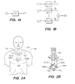
- FIG. 2A the upper portion of a human body 100 is shown in outline with the corresponding locations of aorta 101, esophagus 102, trachea 103, and bronchi 104a and 104b (all shown in dotted line) and suprasternal notch 105. These internal vessels and organs are more clearly depicted in FIG. 2B . With reference to FIGS. 2A and 2B , the outflow tract of the left ventricle of the heart is ascending aorta 101a.
- Segment 101b of the artery passes in front of right bronchus 104a, in front of trachea 103 and then arches behind left bronchus 104b into the descending aorta 101c, which leads towards the lower part of the body.
- the measurement of blood flow from ascending aorta 101a accurately measures the volume of blood ejected from the left ventricle.
- the orientation of electrodes on or near the aorta are expected to have a large effect on both the magnitude and the type of signal produced by the sense electrodes.
- experiments using a rigid plastic pipe have shown that electrodes placed orthogonal to flow generate a signal that varies linearly with flow in the pipe, while electrodes placed parallel to flow detect changes in flow and the presence or absence of turbulence.
- the intra-thoracic aorta is not a straight rigid pipe.
- the aorta in the region of interest makes a complex (i.e. more than 180 degree) turn. Since the orientation of the electrodes with respect to flow is important, and it is difficult to identify the exact orientation of an electrode with respect to the aorta, previously-known BIA methods are believed not to produce reliable or reproducible results.
- the impact of electrode orientation on BIA measurement apparatus and methods is reduced by measuring a three-dimensional impedance field, and using algorithms that relate the three-dimensional impedance field to cardiac output. Measurement of the three-dimensional impedance field is accomplished using three orthogonal pairs of sense electrodes positioned near the aorta, as discussed in detail hereinbelow.
- the three orthogonal pairs of sense electrodes are substantially orthogonal, but need not be precisely orthogonal in a mathematical sense. Considerable variation from a precise orthogonal relationship between the pairs of the electrodes is acceptable, and will provide clinically useful results.
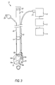
- Measurement apparatus 10 includes endotracheal tube 12, including inflatable cuff 16 disposed near a distal end of endotracheal tube 12, and a lumen for ventilating the patient. Additionally, endotracheal tube 12 includes shaft electrode 14, which serves as an electrical ground electrode for measurement apparatus 10. Sense electrodes 18a-18e are mounted on inflatable cuff 16 to form three orthogonal pairs of sense electrodes. Additionally, current electrode 20 is mounted on inflatable cuff 16.
- Electrodes including shaft electrode 14, sense electrodes 18a-18e, and current electrode 20 are connected via cable 22 and connector 24 to impedance recorder 110.
- Cable 22 may comprise a shielded cable containing multiple conductors or a ribbon cable, and may be disposed within endotracheal tube 12, parallel to endotracheal tube 12, or wrapped around endotracheal tube 12.
- Measurement apparatus 10 also includes digital sampler 112, and computer 114.
- Sense electrodes 18a-18e, current electrode 20, and shaft electrode 14 are preferably composed of a conductive silver ink, printed or silk screened onto a polyethylene backing.
- Sense electrodes 18a-18e and current electrode 20 are preferably each 6mm square, while shaft electrode 14 preferably comprises a 15mm wide band disposed on the shaft of endotracheal tube 12. All of the electrodes have a smooth surface, and are atraumatic to the tracheal mucosa.
- inflatable cuff 16 is in fluid communication with insufflation port 28 via lumen 30 of endotracheal tube 12.
- inflatable cuff 16 When inflated, inflatable cuff 16 retains endotracheal tube 12 in position within the patient's airway, and provides a substantially airtight seal, thereby preventing inadvertent movement of the endotracheal tube.
- Inflatable cuff 16 also urges sense electrodes 18a-18e and current electrode 20 into contact with the interior wall of the trachea.
- Inflatable cuff 16 may be inflated using conventional inflation means (i.e., a gas filled syringe) connected to insufflation port 28 via lumen 30.
- inflatable cuff 16 may be replaced by another suitable type of expandable member for urging the sense electrodes against the interior wall of the patient's airway, such as an expanding mandrel, or other mechanical arrangement.
- the proximal end of endotracheal tube 12 may include reference marks 32 on the circumference of the tube that reflect the circumferential orientation of endotracheal tube 12 within the patient's trachea.
- the reference marks may be used to assist in placement of the sense electrodes and current electrode.
- Endotracheal tube 12 may also include a depth marker (not shown) to assist in determining the proper depth of placement.
- endotracheal tube 12 is inserted into the patient through the oral or nasal cavity, past the epiglottis and into the trachea in accordance with standard intubation practice.
- access to the trachea may be had through a surgical opening at the suprasternal notch by conventional tracheotomy.
- Endotracheal tube 12 is positioned so that inflatable cuff 16 is located near the aorta, and inflatable cuff 16 is inflated, causing sense electrodes 18a-18e and current electrode 20 to contact the tracheal mucosa.
- Shaft electrode 14 contacts the oral mucosa several centimeters above the aorta, and serves as a ground electrode.
- An alternating current preferably a sinusoidal current having a predetermined frequency
- the alternating current preferably has an amplitude of approximately 2 mA, and a frequency in the range of 5 KHz to 1 MHZ, typically 100 KHz. It should be noted that at frequencies below 1 KHz, cardiac stimulation can occur.
- the first orthogonal pair of electrodes comprises sense electrodes 18a and 18b
- the second orthogonal pair of electrodes comprises sense electrodes 18c and 18d
- the third orthogonal pair comprises sense electrodes 18a and 18e.
- These impedance signals are digitally sampled at fixed intervals, preferably approximately 400 samples per second, by digital sampler 112.
- the digital samples are provided to computer 114, which may record the samples, display graphs of the samples, apply algorithms in accordance with the principles of the present invention to determine cardiac output, and apply any additional algorithms to the digital samples.
- Impedance recorder 110, digital sampler, and computer 112 may also record and digitize electrocardiogram (ECG) signals for use in determining cardiac output.
- ECG electrocardiogram
- Various parameters related to the ECG signal may be used in the algorithms described hereinbelow.
- SV ventricular stroke volume
- SV may be continuously computed and updated on a display (not shown) associated with computer 114, and may consist of a running average of the current and a user-selectable number of preceding cardiac cycles. Cardiac output may then be computed as the product of the instantaneous average SV and the heart rate, and also displayed numerically.
- the three-dimensional impedance field is determined by combining the measurements from the three orthogonal pairs of sense electrodes.
- the impedance signal will be referred to as Z, with Z x , Z y , and Z z being the impedance signals along each of the three orthogonal axes.
- Z 0 will be used to refer to the steady state impedance, with Z 0x , Z 0y , and Z 0z being the steady state impedance along each of the three orthogonal axes.
- DZ A signal corresponding to the difference between the impedance and the mean of the impedance signal over time
- DZ signals representing this difference along each of the three axes
- DZ x , DZ y , and DZ z signals representing this difference along each of the three axes
- the Kubicek equation is applied to a single pair of sense electrodes, that measure only a single impedance signal.
- the calculated stroke volume given by the Kubicek equation is highly position and orientation dependent.
- the Bernstein-Sramek formula relating SV to impedance has a basic form similar to the form of the Kubicek equation.
- Equation (5) the formulation of the Bernstein-Sramek algorithm given in equation (5) is expressed in terms of a single impedance value.
- the results of the Bernstein-Sramek algorithm also are highly dependent on the position and orientation of the sense electrodes.
- the empirically determined scaling factors m x , m y , and m z recognize the fact that no simple physical model can adequately relate the impedance signal and cardiac output.
- Each of the three individual x, y, and z terms in the three-dimensional formulation of the equation (7) may be used separately as an indicator of stroke volume, but equation (7) normalizes the effect of sense electrode position and orientation.
- Equation (8) provides a differential term, that represents three-dimensional changes in flow velocity with time.
- the three empirically derived m parameters recognize the lack of a simple physical model relating impedance with cardiac output.
- each of the three individual terms for each of the axes may be useful in computing the ventricular stroke volume.
- Other parameters also may be useful for computing stroke volume from an impedance signal. For example, it is possible to determine whether there is turbulence in the flow from the timing of the impedance signal. This information is useful, since the presence of turbulence indicates a high flow rate, with velocities exceeding the Reynolds number. Conversely, the absence of turbulence indicates a lower flow rate.
- ⁇ 85 represents the time spent at 85% or more of peak flow.
- ⁇ d represents the decay time, and measures the time between 95% of the peak amplitude of the signal on the up-slope, and 60% of the peak amplitude on the downslope.
- the signals I 1 , I 2 , I 3 , I 4 , and I 5 which represent the potential between each of the five sense electrodes 18a-18e and ground, may be useful.
- Other potentially useful parameters include ejection time, time to peak of the first derivative of the DZ signal, and other timing parameters derived from the impedance signal.
- Signals relating to an ECG such as the timing of the R wave (i.e., the maximum peak of the ECG signal) may also be used.
- a measurement of arterial pressure may also be used to improve the accuracy of the multiparameter model of the present invention. If arterial pressure is included as a parameter in the multiparameter model described hereinbelow, correlations may be improved, and error may be reduced.
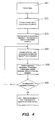
- an algorithm may be generated using stepwise multiple linear regression with all of the equations and parameters that individually correlate with stroke volume.
- step 201 data are collected for multiple subjects under a variety of occlusion conditions.
- the data include impedance measurements along each of three axes, as discussed hereinabove, the I 1 - I 5 measurements, and other parameters for the algorithms described hereinabove. Additionally, data are collected on the actual stroke volume, using, for example, a transit time flow probe.
- the data are used with the various algorithms to compute a predicted stroke volume for each of the algorithms. These results, as well as the measurements of impedance, I 1 - I 5 , and other parameters that correlate with stroke volume are used as independent variables in the stepwise multiple linear regression.
- the stepwise multiple linear regression equation begins with no independent variables.
- the independent variable with the highest F test is added to the equation, in a manner similar to forward selection.
- backwards elimination is performed on the set of independent variables to test for redundancy. If a redundant variable is detected, it is eliminated.
- step 206 the forward selection (step 204) and backward elimination (step 205) are repeated until all of the independent variables have been added to the equation, or have been eliminated from the equation.
- This technique combines the best characteristics of forward selection and backward elimination.
- the first variable added is the strongest predictor of the dependent variable and redundant independent variables are eliminated. This method is used to determine which parameters will be included in the final multi-parameter algorithm for stroke volume.
- the final multi-parameter algorithm for stroke volume may be used with the apparatus of the present invention to monitor cardiac output by programming computer 114 to continuously apply the final multi-parameter algorithm to compute the stroke volume from the data collected by the sense electrodes. Cardiac output may then be computed as the product of the instantaneous average stroke volume and the heart rate.
- FIG. 5 an alternative embodiment of the three-dimensional impedance measurement device of the present invention is described, which is designed for esophageal use, rather than tracheal use.
- This embodiment may be advantageously used, for example, in previously intubated patients. Extubating a patient having an endotracheal tube to replace it with a tube having sensors for measuring impedance in accordance with the principles of the present invention may involve an unacceptable degree of discomfort or risk to the patient.
- impedance measurements may be used to compute cardiac output in previously intubated patients without disturbing an endotracheal tube that is already in place.
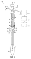
- Measurement apparatus 50 comprises an esophageal stethoscope, including tube 53, stethoscope balloon 54 disposed at a distal end of tube 53, and thermister 56.
- Shaft electrode 58 which serves as an electrical ground electrode for measurement apparatus 50, is mounted on tube 53.
- Inflatable cuff 60 also is mounted on tube 53, and sense electrodes 62a-62e are mounted on inflatable cuff 60 to form three orthogonal pairs of sense electrodes. Additionally, current electrode 64 is mounted on inflatable cuff 60.
- Electrodes including shaft electrode 58, sense electrodes 62a-62e, and current electrode 64 are connected via cable 66 and connector 68 to impedance recorder 110.
- Cable 66 may comprise a shielded cable containing multiple conductors or a ribbon cable, and may be disposed within tube 53, parallel to tube 53, or wrapped around tube 53.
- Measurement apparatus 50 also includes digital sampler 112, and computer 114.
- sense electrodes 62a-62e, current electrode 64, and shaft electrode 58 preferably are composed of a conductive silver ink, printed or silk screened onto a polyethylene backing.
- Sense electrodes 62a-62e and current electrode 64 preferably are each 6mm square, while shaft electrode 58 preferably comprises a 15mm wide band. It will be understood by one skilled in the relevant arts that other dimensions may be used, and that the size of inflatable cuff 60 and the sizes and spacing of the electrodes may be larger in the esophageal embodiment than in the endotracheal embodiment described hereinabove, due to the larger diameter of the esophagus.
- inflatable cuff 60 The interior of inflatable cuff 60 is in fluid communication with insufflation port 70 via lumen 72.
- inflatable cuff 60 retains the esophageal stethoscope in position within the patient's esophagus, thereby preventing inadvertent movement.
- Inflatable cuff 60 also urges sense electrodes 62a-62e and current electrode 64 into contact with the interior wall of the esophagus.
- Inflatable cuff 60 may be inflated using conventional inflation means (i.e., a gas filled syringe) connected to insufflation port 70 via lumen 72.
- inflatable cuff 60 may be replaced by another suitable type of expandable member for urging the electrodes against the interior wall of the patient's esophagus, such as an expanding mandrel, or other mechanical arrangement.
- the esophageal stethoscope of measurement apparatus 50 may be used for ascultation and temperature measurements.
- measurement apparatus 50 includes stethoscope hookup 74, and thermister lead 76.
- stethoscope hookup 74 and thermister lead 76 may be connected to standard recording equipment.
- tube 53 is inserted through the mouth into a patient's esophagus, and positioned so that inflatable cuff 60 is located near the aorta.
- Inflatable cuff 60 is then inflated, causing sense electrodes 62a-62e and current electrode 64 to contact the interior wall of the patient's esophagus.
- Shaft electrode 58 contacts the esophagus several centimeters above the aorta, and serves as a ground electrode.
- An alternating current preferably a sinusoidal current having a predetermined frequency
- the alternating current preferably has an amplitude of approximately 2 mA, and a frequency in the range of 5 KHz to 1 MHz, typically 100 KHz.
- signals indicative of a drop in voltage between the two electrodes of each of the orthogonal pairs of electrodes are received at impedance recorder 110.
- the first orthogonal pair of electrodes comprises sense electrodes 62a and 62b
- the second orthogonal pair of electrodes comprises sense electrodes 62c and 62d
- the third orthogonal pair comprises sense electrodes 62a and 62e.
- These impedance signals are digitally sampled at fixed intervals, preferably approximately 400 samples per second, by digital sampler 112.
- the digital samples are provided to computer 114, which may record the samples, display graphs of the samples, apply algorithms in accordance with the principles of the present invention to determine cardiac output, or apply any other algorithms to the digital samples.
- a multi-parameter algorithm similar to that discussed hereinabove computes the stroke volume based on impedance measurements.
- the algorithm may be derived using stepwise multiple linear regression, in the manner described hereinabove.
- diodes suitable for employing blood oximetry techniques based on near infrared light absorption also may be disposed on the endotracheal tube to measure blood oxygen saturation levels.
- diodes suitable for employing blood oximetry techniques based on near infrared light absorption also may be disposed on the endotracheal tube to measure blood oxygen saturation levels.
- multiple light emitting diodes, including one or more red-light and infrared emitting diodes may be disposed on the endotracheal tube, on the inflatable cuff or member, or both, for obtaining blood oxygen saturation measurements using transreflectance oximetry techniques, as described, for example, in U.S. Patent No. 5,099,842 , the entirety of which is incorporated herein by reference.
- FIG. 6A use of the apparatus of the present invention is described as a controller for the administration of fluids, or of medication, such as dobutamine, dopamine, epinephrine, norepinephrine, nitroprusside, or other substances for medical management of hemodynamics.
- cardiac output is measured by apparatus 170, which may be either of the foregoing embodiments, and includes tube 171 disposed in patient 190, either in the trachea or the esophagus.
- Apparatus 170 is used to monitor hemodynamic status and as a metric to control the administration of fluids or medication intravenously via lumen 172 coupled to fluid supply system 173.
- Computer 174 which may be the same computer that computes cardiac output from the impedance values output by impedance recorder 110 and digital sampler 112, controls fluid supply system 172.
- the apparatus of FIG. 6A provides a closed-loop system wherein the amount of fluid or other medication injected into the patient is controlled by the cardiac output computed as described hereinabove.
- cardiac output is measured by apparatus 181, which may be any of the foregoing embodiments, and includes tube 182 disposed in patient 190, either in the trachea or the esophagus.
- apparatus 181 is used, in conjunction with computer 183, as a metric to control the setting of pacemaker 180 as described hereinafter.
- a baseline cardiac output measurement is first obtained and then the heart rate is reduced by a predetermined amount, e.g., two beats/min, while the cardiac output is continuously monitored by apparatus 181. As long as the cardiac output increases or remains unchanged, the heart rate is periodically further lowered by the predetermined amount, for example, by 2 beats/min every 15 minutes. The process of reducing heart rate while monitoring cardiac output is continued until either a minimum desired heart rate is obtained or the cardiac output measured by apparatus 181 begins to decrease. If the cardiac output is determined to have decreased, the heart rate is returned to the preceding higher rate.
- a predetermined amount e.g., two beats/min
- the resulting multi-parameter algorithm contained weighted terms for 53 parameters, including I 1 , I 2 , I 3 , I 4 , I 5 , Z 0x , Z 0y , Z 0z , equation (7), each of the x, y, and z terms of equation (7), equation (8), and each of the x, y, and z terms of the equation (8), and other parameters relating to timing, and to the ECG signal.
- the resulting algorithm was able to compute a stroke volume from the various impedance measurements while maintaining a high degree of invariance to exact positioning and rotation of the sense electrodes, and an ability to be used across individuals without need for recalibration for each individual in which the device was used.
- Table 1 shows the list of independent variables (i.e., parameters) in the equation that resulted from stepwise linear regression, and the weight assigned to each of the parameters.
- equation (9) described hereinabove, to compute stroke volume, the weight of each parameter is multiplied by the value of the parameter, and the results for all weights and parameters are summed. A constant value is then added to the sum to provide the metric for stroke volume.
- C 55.935091.
- MXDZDTW y See MXDZDTW x , but for DZ y .
- 34 -0.223327 MXDZDTW y S See MXDZDTW x S, but for DZ y .
- 35 22.520111 MNDZDT y See MNDZDT x , but for DZ y .
- 36 0.293328 MNDZDT y E See MNDZDT x E, but for DZ y .
- 37 -10.853298 MNDZDTW y See MNDZDTW x , but for DZ y . 38 0.060624 MNDZDTW y E See MNDZDTW x E, but for DZ y .
- MXDZDT z S See MXDZDT x S, but for DZ z . 47 23.561712 MXDZDTW z See MXDZDTW x , but for Dz z . 48 -0.126598 MXDZDTW z S See MXDZDTW x S, but for DZ z . 49 -2.202599 MNDZDT z See MNDZDT x , but for DZ z . 50 0.206271 MNDZDT z E See MNDZDT x E, but for DZ z . 51 0.325518 MNDZDTW z See MNDZDTW x , but for DZ z .
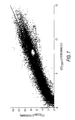
- FIG. 7 shows the results of a test of the apparatus and derived algorithm of Table 1 on a group of ten pigs.
- the axis labeled CO ECOM shows the cardiac output calculated from impedance measurements taken with the apparatus of the present invention by the multi-parameter algorithm with the weights and parameters given in Table 1.
- the axis labeled CO TTFP shows the cardiac output determined by a transit time flow probe. The data shown in the graph is from 29,657 heart beats recorded during occlusion tests from the ten animals during a 24 hour recording period.
Landscapes
- Health & Medical Sciences (AREA)
- Life Sciences & Earth Sciences (AREA)
- Molecular Biology (AREA)
- Heart & Thoracic Surgery (AREA)
- Physics & Mathematics (AREA)
- Veterinary Medicine (AREA)
- Biophysics (AREA)
- Pathology (AREA)
- Engineering & Computer Science (AREA)
- Animal Behavior & Ethology (AREA)
- Surgery (AREA)
- Medical Informatics (AREA)
- Public Health (AREA)
- Hematology (AREA)
- Biomedical Technology (AREA)
- General Health & Medical Sciences (AREA)
- Cardiology (AREA)
- Physiology (AREA)
- Radiology & Medical Imaging (AREA)
- Nuclear Medicine, Radiotherapy & Molecular Imaging (AREA)
- Measuring Pulse, Heart Rate, Blood Pressure Or Blood Flow (AREA)
- Measurement And Recording Of Electrical Phenomena And Electrical Characteristics Of The Living Body (AREA)
- Electrotherapy Devices (AREA)
- Measuring And Recording Apparatus For Diagnosis (AREA)
- Measurement Of The Respiration, Hearing Ability, Form, And Blood Characteristics Of Living Organisms (AREA)
Applications Claiming Priority (3)
| Application Number | Priority Date | Filing Date | Title |
|---|---|---|---|
| US458186 | 1999-12-08 | ||
| US09/458,186 US6292689B1 (en) | 1996-04-17 | 1999-12-08 | Apparatus and methods of bioelectrical impedance analysis of blood flow |
| PCT/US2000/032792 WO2001041638A1 (en) | 1999-12-08 | 2000-12-04 | Apparatus and methods of bioelectrical impedance analysis of blood flow |
Publications (3)
| Publication Number | Publication Date |
|---|---|
| EP1235514A1 EP1235514A1 (en) | 2002-09-04 |
| EP1235514A4 EP1235514A4 (en) | 2007-08-08 |
| EP1235514B1 true EP1235514B1 (en) | 2014-01-15 |
Family
ID=23819721
Family Applications (1)
| Application Number | Title | Priority Date | Filing Date |
|---|---|---|---|
| EP00982367.5A Expired - Lifetime EP1235514B1 (en) | 1999-12-08 | 2000-12-04 | Apparatus and methods of bioelectrical impedance analysis of blood flow |
Country Status (6)
| Country | Link |
|---|---|
| US (1) | US6292689B1 (enExample) |
| EP (1) | EP1235514B1 (enExample) |
| JP (1) | JP4914551B2 (enExample) |
| AU (1) | AU781264B2 (enExample) |
| CA (1) | CA2393008A1 (enExample) |
| WO (1) | WO2001041638A1 (enExample) |
Families Citing this family (99)
| Publication number | Priority date | Publication date | Assignee | Title |
|---|---|---|---|---|
| US6445942B1 (en) * | 1999-09-15 | 2002-09-03 | Resmed Ltd | Measurement of respiratory effort using a suprasternal sensor |
| US6758216B1 (en) | 1999-09-15 | 2004-07-06 | Resmed Limited | Ventilatory assistance using an external effort sensor |
| US6517492B2 (en) * | 2001-02-22 | 2003-02-11 | Texon Technologies Ltd. | Method and apparatus for assessment of cardiac function by monitoring movement of the trachea |
| US6907288B2 (en) * | 2001-04-10 | 2005-06-14 | Cardiac Pacemakers, Inc. | Cardiac rhythm management system adjusting rate response factor for treating hypotension |
| US6912420B2 (en) * | 2001-04-10 | 2005-06-28 | Cardiac Pacemakers, Inc. | Cardiac rhythm management system for hypotension |
| US7191000B2 (en) | 2001-07-31 | 2007-03-13 | Cardiac Pacemakers, Inc. | Cardiac rhythm management system for edema |
| AU2003213129A1 (en) * | 2002-04-15 | 2003-11-03 | Boasso America Corporation (A Louisiana Corporation) | Method and apparatus for supplying bulk product to an end user |
| AUPS214502A0 (en) * | 2002-05-06 | 2002-06-06 | Uscom Pty Ltd | Blood flow oxygen measurement |
| AUPS335502A0 (en) * | 2002-07-03 | 2002-07-25 | Uscom Pty Ltd | Pacemaker evaluation method and apparatus |
| US7043293B1 (en) | 2002-12-24 | 2006-05-09 | Cardiodynamics International Corporation | Method and apparatus for waveform assessment |
| AU2003900261A0 (en) * | 2003-01-22 | 2003-02-06 | Uscom Pty Ltd | Method and system for the determination of blood characteristics |
| CN1326487C (zh) * | 2003-06-18 | 2007-07-18 | 魏蔚 | 经气管进行医用监测的装置 |
| US7455643B1 (en) | 2003-07-07 | 2008-11-25 | Nellcor Puritan Bennett Ireland | Continuous non-invasive blood pressure measurement apparatus and methods providing automatic recalibration |
| TW200534827A (en) * | 2004-03-24 | 2005-11-01 | Noninvasive Medical Technologies Llc | Thoracic impedance monitor and electrode array and method of use |
| WO2005110051A2 (en) * | 2004-05-10 | 2005-11-24 | Transoma Medical, Inc. | Portable device for monitoring electrocardiographic signals and indices of blood flow |
| US20060004301A1 (en) * | 2004-06-24 | 2006-01-05 | Kasevich Raymond S | Clinical application of electrical impedance tomography to characterize tissue |
| US7356366B2 (en) * | 2004-08-02 | 2008-04-08 | Cardiac Pacemakers, Inc. | Device for monitoring fluid status |
| US7387610B2 (en) | 2004-08-19 | 2008-06-17 | Cardiac Pacemakers, Inc. | Thoracic impedance detection with blood resistivity compensation |
| DE602004032070D1 (de) * | 2004-11-18 | 2011-05-12 | Japan Health Science Found | System zur behandlung von herzkrankheiten |
| US20060111641A1 (en) * | 2004-11-19 | 2006-05-25 | Applied Cardiac Systems, Inc. | System and method for ICG recording and analysis |
| US7570989B2 (en) * | 2004-11-22 | 2009-08-04 | Cardiodynamics International Corporation | Method and apparatus for signal assessment including event rejection |
| US7630763B2 (en) | 2005-04-20 | 2009-12-08 | Cardiac Pacemakers, Inc. | Thoracic or intracardiac impedance detection with automatic vector selection |
| US7603170B2 (en) * | 2005-04-26 | 2009-10-13 | Cardiac Pacemakers, Inc. | Calibration of impedance monitoring of respiratory volumes using thoracic D.C. impedance |
| US9089275B2 (en) | 2005-05-11 | 2015-07-28 | Cardiac Pacemakers, Inc. | Sensitivity and specificity of pulmonary edema detection when using transthoracic impedance |
| US7907997B2 (en) | 2005-05-11 | 2011-03-15 | Cardiac Pacemakers, Inc. | Enhancements to the detection of pulmonary edema when using transthoracic impedance |
| US7340296B2 (en) | 2005-05-18 | 2008-03-04 | Cardiac Pacemakers, Inc. | Detection of pleural effusion using transthoracic impedance |
| US9839781B2 (en) | 2005-08-22 | 2017-12-12 | Cardiac Pacemakers, Inc. | Intracardiac impedance and its applications |
| US8116858B2 (en) * | 2005-08-22 | 2012-02-14 | John Koblanski | Methods and apparatus for monitoring heart motions |
| EP2219517B1 (en) * | 2007-10-12 | 2019-03-06 | ConMed Corporation | Apparatus for the measurement of cardiac output and method for its fabrication |
| US20090299269A1 (en) * | 2008-05-29 | 2009-12-03 | John Foley | Vascular stimulation to aid intravascular cell replacement therapy |
| US8660799B2 (en) | 2008-06-30 | 2014-02-25 | Nellcor Puritan Bennett Ireland | Processing and detecting baseline changes in signals |
| US8398556B2 (en) | 2008-06-30 | 2013-03-19 | Covidien Lp | Systems and methods for non-invasive continuous blood pressure determination |
| US8506498B2 (en) | 2008-07-15 | 2013-08-13 | Nellcor Puritan Bennett Ireland | Systems and methods using induced perturbation to determine physiological parameters |
| US8702613B2 (en) * | 2008-09-22 | 2014-04-22 | 3Dt Holdings, Llc | Methods for determining fractional flow reserve |
| US9301697B2 (en) | 2008-09-30 | 2016-04-05 | Nellcor Puritan Bennett Ireland | Systems and methods for recalibrating a non-invasive blood pressure monitor |
| US9314168B2 (en) | 2008-09-30 | 2016-04-19 | Nellcor Puritan Bennett Ireland | Detecting sleep events using localized blood pressure changes |
| US8532751B2 (en) | 2008-09-30 | 2013-09-10 | Covidien Lp | Laser self-mixing sensors for biological sensing |
| US9687161B2 (en) | 2008-09-30 | 2017-06-27 | Nellcor Puritan Bennett Ireland | Systems and methods for maintaining blood pressure monitor calibration |
| US8386010B2 (en) * | 2008-10-23 | 2013-02-26 | Covidien Lp | Surgical tissue monitoring system |
| PL2370015T3 (pl) | 2008-11-11 | 2017-07-31 | Shifamed Holdings, Llc | Niskoprofilowy zespół elektrodowy |
| US9795442B2 (en) | 2008-11-11 | 2017-10-24 | Shifamed Holdings, Llc | Ablation catheters |
| US8216136B2 (en) | 2009-03-05 | 2012-07-10 | Nellcor Puritan Bennett Llc | Systems and methods for monitoring heart rate and blood pressure correlation |
| CA2764859C (en) | 2009-06-24 | 2018-09-25 | Shifamed, Llc | Steerable medical delivery devices and methods of use |
| US8290730B2 (en) | 2009-06-30 | 2012-10-16 | Nellcor Puritan Bennett Ireland | Systems and methods for assessing measurements in physiological monitoring devices |
| US9198582B2 (en) | 2009-06-30 | 2015-12-01 | Nellcor Puritan Bennett Ireland | Determining a characteristic physiological parameter |
| US8628477B2 (en) | 2009-07-31 | 2014-01-14 | Nellcor Puritan Bennett Ireland | Systems and methods for non-invasive determination of blood pressure |
| US8467844B2 (en) * | 2009-09-21 | 2013-06-18 | Neurovision Medical Products, Inc. | Electrode for prolonged monitoring of laryngeal electromyography |
| US9220440B2 (en) | 2009-09-21 | 2015-12-29 | Nellcor Puritan Bennett Ireland | Determining a characteristic respiration rate |
| JP5721721B2 (ja) * | 2009-09-23 | 2015-05-20 | ライトラボ・イメージング・インコーポレーテッド | 管腔形態および血管抵抗測定データ収集のシステム、装置および方法 |
| US12426789B2 (en) | 2009-09-23 | 2025-09-30 | Lightlab Imaging, Inc. | Blood vessel lumen morphology and minimum lumen area measurements data collection by intravascular imaging systems for stenosis or stent planning |
| US9066660B2 (en) | 2009-09-29 | 2015-06-30 | Nellcor Puritan Bennett Ireland | Systems and methods for high-pass filtering a photoplethysmograph signal |
| US8463347B2 (en) | 2009-09-30 | 2013-06-11 | Nellcor Puritan Bennett Ireland | Systems and methods for normalizing a plethysmograph signal for improved feature analysis |
| WO2011041684A2 (en) | 2009-10-02 | 2011-04-07 | Medtronic-Xomed, Inc. | Endotracheal tube apparatus |
| US20110213264A1 (en) * | 2010-02-26 | 2011-09-01 | Nellcor Puritan Bennett Llc | Sensor on non-sealing portion of tracheal tube cuff |
| JP5836979B2 (ja) | 2010-03-04 | 2015-12-24 | コーニンクレッカ フィリップス エヌ ヴェKoninklijke Philips N.V. | 多機能栄養管 |
| WO2011116303A1 (en) | 2010-03-19 | 2011-09-22 | Micropen Technologies Corporation | Thermocouple device |
| CN102917748B (zh) | 2010-03-24 | 2015-04-01 | 施菲姆德控股有限责任公司 | 血管内组织破坏 |
| US9451887B2 (en) | 2010-03-31 | 2016-09-27 | Nellcor Puritan Bennett Ireland | Systems and methods for measuring electromechanical delay of the heart |
| US8898037B2 (en) | 2010-04-28 | 2014-11-25 | Nellcor Puritan Bennett Ireland | Systems and methods for signal monitoring using Lissajous figures |
| US9655677B2 (en) | 2010-05-12 | 2017-05-23 | Shifamed Holdings, Llc | Ablation catheters including a balloon and electrodes |
| CN105105844B (zh) | 2010-05-12 | 2017-12-15 | 施菲姆德控股有限责任公司 | 小轮廓的电极组件 |
| GB2496074B (en) * | 2010-07-13 | 2016-07-20 | Sandhill Scient Inc | Apparatus and method for detecting and measuring condition of esophageal mucosa and indications of gastroesophageal reflux disease |
| US8825428B2 (en) | 2010-11-30 | 2014-09-02 | Neilcor Puritan Bennett Ireland | Methods and systems for recalibrating a blood pressure monitor with memory |
| US9259160B2 (en) | 2010-12-01 | 2016-02-16 | Nellcor Puritan Bennett Ireland | Systems and methods for determining when to measure a physiological parameter |
| US9357934B2 (en) | 2010-12-01 | 2016-06-07 | Nellcor Puritan Bennett Ireland | Systems and methods for physiological event marking |
| JP6527329B2 (ja) | 2011-05-03 | 2019-06-05 | シファメド・ホールディングス・エルエルシー | 操縦可能な送達シース |
| US20140243821A1 (en) | 2011-09-30 | 2014-08-28 | Covidien Lp | Energy delivery device and methods of use |
| US9060695B2 (en) | 2011-11-30 | 2015-06-23 | Covidien Lp | Systems and methods for determining differential pulse transit time from the phase difference of two analog plethysmographs |
| US9931079B2 (en) | 2012-01-04 | 2018-04-03 | Medtronic Xomed, Inc. | Clamp for securing a terminal end of a wire to a surface electrode |
| US8961550B2 (en) | 2012-04-17 | 2015-02-24 | Indian Wells Medical, Inc. | Steerable endoluminal punch |
| US9226792B2 (en) | 2012-06-12 | 2016-01-05 | Medtronic Advanced Energy Llc | Debridement device and method |
| US9060744B2 (en) | 2012-11-29 | 2015-06-23 | Medtronic Xomed, Inc. | Endobronchial tube apparatus |
| US9913594B2 (en) | 2013-03-14 | 2018-03-13 | Medtronic Xomed, Inc. | Compliant electrode for EMG endotracheal tube |
| US10349824B2 (en) | 2013-04-08 | 2019-07-16 | Apama Medical, Inc. | Tissue mapping and visualization systems |
| CN105228547B (zh) | 2013-04-08 | 2019-05-14 | 阿帕玛医疗公司 | 心脏消融导管 |
| US10098694B2 (en) | 2013-04-08 | 2018-10-16 | Apama Medical, Inc. | Tissue ablation and monitoring thereof |
| US11207130B2 (en) | 2015-02-18 | 2021-12-28 | Medtronic Xomed, Inc. | RF energy enabled tissue debridement device |
| US10376302B2 (en) | 2015-02-18 | 2019-08-13 | Medtronic Xomed, Inc. | Rotating electrical connector for RF energy enabled tissue debridement device |
| US10188456B2 (en) | 2015-02-18 | 2019-01-29 | Medtronic Xomed, Inc. | Electrode assembly for RF energy enabled tissue debridement device |
| US9451888B1 (en) | 2015-03-27 | 2016-09-27 | Cordeus, Inc. | Method and apparatus for determination of left ventricular stroke volume and cardiac output using the arteries of the forearm |
| CA2979884A1 (en) | 2015-03-27 | 2016-10-06 | Shifamed Holdings, Llc | Steerable medical devices, systems, and methods of use |
| CA2982823A1 (en) | 2015-04-24 | 2016-10-27 | Shifamed Holdings, Llc | Steerable medical devices, systems, and methods of use |
| EP3750477A1 (en) * | 2015-05-07 | 2020-12-16 | Ecom Medical, Inc. | Systems and method for fabricating invasive ecg probe |
| EP3373794B1 (en) | 2015-11-09 | 2022-01-05 | Kalila Medical, Inc. | Steering assemblies for medical devices |
| CN108348146A (zh) | 2015-11-16 | 2018-07-31 | 阿帕玛医疗公司 | 能量传递装置 |
| US11147515B2 (en) | 2016-02-16 | 2021-10-19 | Ecom Medical, Inc. | Systems and methods for obtaining cardiovascular parameters |
| WO2018035000A1 (en) | 2016-08-13 | 2018-02-22 | Ecom Medical, Inc. | Medical devices with layered conductive elements and methods for manufacturing the same |
| US11266467B2 (en) | 2016-10-25 | 2022-03-08 | Navix International Limited | Systems and methods for registration of intra-body electrical readings with a pre-acquired three dimensional image |
| KR101812587B1 (ko) | 2016-11-18 | 2018-01-30 | 주식회사 바이랩 | 피험자의 영상 모니터링 장치 및 그 방법과, 영상 모니터링 시스템 |
| US11730395B2 (en) | 2017-01-12 | 2023-08-22 | Navix International Limited | Reconstruction of an anatomical structure from intrabody measurements |
| US11471067B2 (en) | 2017-01-12 | 2022-10-18 | Navix International Limited | Intrabody probe navigation by electrical self-sensing |
| EP3568068A1 (en) * | 2017-01-12 | 2019-11-20 | Navix International Limited | Systems and methods for reconstruction of intra-body electrical readings to anatomical structure |
| US11583202B2 (en) | 2017-08-17 | 2023-02-21 | Navix International Limited | Field gradient-based remote imaging |
| CA3072055A1 (en) | 2017-08-21 | 2019-02-28 | Ecom Medical, Inc. | Systems and methods for applying materials to medical devices |
| US11110240B2 (en) | 2017-09-07 | 2021-09-07 | Medtronic Xomed, Inc. | Endotracheal tube with tube coating |
| US11376421B2 (en) * | 2017-11-09 | 2022-07-05 | The Methodist Hospital System | Neurostimulation induced medicine devices and related methods of use |
| US10524668B2 (en) | 2018-02-05 | 2020-01-07 | Aerobex, Inc. | Method and apparatus for determination of left ventricular stroke volume and cardiac output using the arteries of the forearm by means of integration technique |
| US11291382B2 (en) | 2018-06-01 | 2022-04-05 | Diversatek Healthcare, Inc. | System and method for detecting and measuring the condition of intraluminal esophageal mucosa |
| US20250302328A1 (en) | 2024-03-28 | 2025-10-02 | Anusar Inc. | Device and method for real time assessment and monitoring of thoracic fluid, air trapping and ventilation |
Family Cites Families (33)
| Publication number | Priority date | Publication date | Assignee | Title |
|---|---|---|---|---|
| US3149627A (en) * | 1962-04-25 | 1964-09-22 | Samuel M Bagno | Plethysmograph |
| US3340867A (en) | 1964-08-19 | 1967-09-12 | Univ Minnesota | Impedance plethysmograph |
| USRE30101E (en) * | 1964-08-19 | 1979-09-25 | Regents Of The University Of Minnesota | Impedance plethysmograph |
| US3651318A (en) | 1970-01-26 | 1972-03-21 | Jan A Czekajewski | Cardiac output computer |
| US3726269A (en) | 1971-11-24 | 1973-04-10 | W Webster | Cardiovascular catheter for thermal dilution measurement |
| SE363230B (enExample) | 1973-02-09 | 1974-01-14 | Hoffmann La Roche | |
| US4437469A (en) | 1980-09-29 | 1984-03-20 | Rush-Presbyterian-St. Luke's Medical Center | System for determining characteristics of blood flow |
| US4450527A (en) | 1982-06-29 | 1984-05-22 | Bomed Medical Mfg. Ltd. | Noninvasive continuous cardiac output monitor |
| GB8431500D0 (en) | 1984-12-13 | 1985-01-23 | Antec Systems | Measurement of thoracic impedances |
| US4671295A (en) | 1985-01-15 | 1987-06-09 | Applied Biometrics, Inc. | Method for measuring cardiac output |
| US4722347A (en) | 1985-01-15 | 1988-02-02 | Applied Biometrics, Inc. | Apparatus for measuring cardiac output |
| US4852580A (en) | 1986-09-17 | 1989-08-01 | Axiom Medical, Inc. | Catheter for measuring bioimpedance |
| US4836214A (en) | 1986-12-01 | 1989-06-06 | Bomed Medical Manufacturing, Ltd. | Esophageal electrode array for electrical bioimpedance measurement |
| US4870578A (en) | 1987-08-19 | 1989-09-26 | Bomed Medical Manufacturing, Ltd. | Diastolic clamp for bioimpedance measuring device |
| US5000190A (en) * | 1988-06-22 | 1991-03-19 | The Cleveland Clinic Foundation | Continuous cardiac output by impedance measurements in the heart |
| US4967759A (en) | 1988-06-29 | 1990-11-06 | Teves Leonides Y | Cardiac monitor with endotracheal sensor |
| US5080107A (en) | 1988-06-29 | 1992-01-14 | Teves Leonides Y | Cardiac monitor with endotracheal sensor |
| DE3900178A1 (de) | 1989-01-05 | 1990-07-12 | Paul Peter Prof D Lunkenheimer | Vorrichtung zur durchfuehrung diagnostischer impedanzmessungen |
| US5125406A (en) | 1989-11-29 | 1992-06-30 | Eet Limited Partnership (Del) | Electrode endotracheal tube |
| US5024228A (en) | 1989-11-29 | 1991-06-18 | Goldstone Andrew C | Electrode endotracheal tube |
| US5005573A (en) | 1990-07-20 | 1991-04-09 | Buchanan Dale C | Endotracheal tube with oximetry means |
| US5063937A (en) * | 1990-09-12 | 1991-11-12 | Wright State University | Multiple frequency bio-impedance measurement system |
| US5203344A (en) | 1991-01-31 | 1993-04-20 | Brigham And Women's Hospital | Method and apparatus for taking bioelectrical impedance measurements using proximally positioned electrodes |
| US5379765A (en) | 1991-06-12 | 1995-01-10 | Kajiwara; Nagao | Monitoring apparatus for use in obtaining bronchial electrocardiogram |
| JP2855556B2 (ja) * | 1991-12-06 | 1999-02-10 | 長雄 梶原 | 気管支誘導心電図の測定装置 |
| DE4205336C1 (enExample) | 1992-02-21 | 1993-05-13 | Gsf - Forschungszentrum Fuer Umwelt Und Gesundheit, Gmbh, 8000 Muenchen, De | |
| IL102300A (en) | 1992-06-24 | 1996-07-23 | N I Medical Ltd | Non-invasive system for determining of the main cardiorespiratory parameters of the human body |
| US5477860A (en) | 1992-11-05 | 1995-12-26 | Synectics Medical, Inc. | Catheter for measuring respiration and respiratory effort |
| US5385146A (en) * | 1993-01-08 | 1995-01-31 | Goldreyer; Bruce N. | Orthogonal sensing for use in clinical electrophysiology |
| US5487391A (en) * | 1994-01-28 | 1996-01-30 | Ep Technologies, Inc. | Systems and methods for deriving and displaying the propagation velocities of electrical events in the heart |
| DE19533663A1 (de) * | 1995-09-12 | 1997-03-13 | Heinemann & Gregori Gmbh | Verfahren und Vorrichtung zur Herzzeitvolumenbestimmung |
| US5697377A (en) * | 1995-11-22 | 1997-12-16 | Medtronic, Inc. | Catheter mapping system and method |
| US5782774A (en) * | 1996-04-17 | 1998-07-21 | Imagyn Medical Technologies California, Inc. | Apparatus and method of bioelectrical impedance analysis of blood flow |
-
1999
- 1999-12-08 US US09/458,186 patent/US6292689B1/en not_active Expired - Lifetime
-
2000
- 2000-12-04 AU AU19412/01A patent/AU781264B2/en not_active Ceased
- 2000-12-04 CA CA002393008A patent/CA2393008A1/en not_active Abandoned
- 2000-12-04 WO PCT/US2000/032792 patent/WO2001041638A1/en not_active Ceased
- 2000-12-04 EP EP00982367.5A patent/EP1235514B1/en not_active Expired - Lifetime
- 2000-12-04 JP JP2001542816A patent/JP4914551B2/ja not_active Expired - Fee Related
Also Published As
| Publication number | Publication date |
|---|---|
| US6292689B1 (en) | 2001-09-18 |
| JP4914551B2 (ja) | 2012-04-11 |
| JP2003527164A (ja) | 2003-09-16 |
| WO2001041638A1 (en) | 2001-06-14 |
| EP1235514A1 (en) | 2002-09-04 |
| CA2393008A1 (en) | 2001-06-14 |
| AU781264B2 (en) | 2005-05-12 |
| AU1941201A (en) | 2001-06-18 |
| EP1235514A4 (en) | 2007-08-08 |
Similar Documents
| Publication | Publication Date | Title |
|---|---|---|
| EP1235514B1 (en) | Apparatus and methods of bioelectrical impedance analysis of blood flow | |
| EP0904012B1 (en) | Apparatus for bioelectrical impedance analysis of blood flow | |
| US5791349A (en) | Apparatus and method of bioelectrical impedance analysis of blood flow | |
| CN100571613C (zh) | 测量血流和血容量的系统、方法和装置 | |
| JP4739753B2 (ja) | 生体インピーダンス法を用いて鬱血性心不全患者をモニタするための装置 | |
| US4836214A (en) | Esophageal electrode array for electrical bioimpedance measurement | |
| US6186955B1 (en) | Noninvasive continuous cardiac output monitor | |
| JP5496510B2 (ja) | 身体の機能および状態の電気的測定のための装置およびプロセス | |
| EP2593006B1 (en) | Method and apparatus for the non-invasive measurement of pulse transit times (ptt) | |
| US20020123674A1 (en) | Process and implantable device for the intrapulmonary assessing of density dependant physical properties of the lung tissue | |
| US20040249297A1 (en) | Apparatus for determining cardiovascular parameters | |
| US9220450B2 (en) | Compositions and methods for measurement of oxygen saturation in blood filled structures | |
| US6496732B1 (en) | Internal cardiac output monitor | |
| US12016826B2 (en) | Systems and methods for bioimpedance body composition measurement | |
| CN109788933B (zh) | 利用超声监测气管内气流的系统和方法 | |
| Kolb et al. | Cardiac output measurement | |
| Kumar et al. | Noninvasive measurement of cardiac output during surgery using a new continuous-wave Doppler esophageal probe | |
| Betteridge et al. | Cardiac output monitoring | |
| Wood et al. | Comparison of right ventricular impedance, pulse pressure and maximal dPdt for determination of hemodynamic stability of ventricular arrhythmias associated with coronary artery disease | |
| Shah et al. | Advanced cardiovascular monitoring | |
| Prabhu et al. | Cardiac output measurement | |
| Arrowsmith et al. | Advanced cardiovascular monitoring | |
| Kong et al. | Cardiac output monitoring | |
| CATHETER | Cardiac output monitoring | |
| HK40006347A (en) | System and method for monitoring airflow in a trachea with ultrasound |
Legal Events
| Date | Code | Title | Description |
|---|---|---|---|
| PUAI | Public reference made under article 153(3) epc to a published international application that has entered the european phase |
Free format text: ORIGINAL CODE: 0009012 |
|
| 17P | Request for examination filed |
Effective date: 20020605 |
|
| AK | Designated contracting states |
Kind code of ref document: A1 Designated state(s): AT BE CH CY DE DK ES FI FR GB GR IE IT LI LU MC NL PT SE TR |
|
| AX | Request for extension of the european patent |
Free format text: AL;LT;LV;MK;RO;SI |
|
| RAP1 | Party data changed (applicant data changed or rights of an application transferred) |
Owner name: CONMED CORPORATION |
|
| A4 | Supplementary search report drawn up and despatched |
Effective date: 20070705 |
|
| RIC1 | Information provided on ipc code assigned before grant |
Ipc: A61B 5/05 20060101AFI20010620BHEP Ipc: A61B 5/029 20060101ALI20070629BHEP |
|
| 17Q | First examination report despatched |
Effective date: 20081013 |
|
| REG | Reference to a national code |
Ref country code: DE Ref legal event code: R079 Ref document number: 60048409 Country of ref document: DE Free format text: PREVIOUS MAIN CLASS: A61B0005050000 Ipc: A61B0005053000 |
|
| RIC1 | Information provided on ipc code assigned before grant |
Ipc: A61B 5/029 20060101ALI20130806BHEP Ipc: A61B 5/053 20060101AFI20130806BHEP |
|
| GRAP | Despatch of communication of intention to grant a patent |
Free format text: ORIGINAL CODE: EPIDOSNIGR1 |
|
| INTG | Intention to grant announced |
Effective date: 20131001 |
|
| GRAS | Grant fee paid |
Free format text: ORIGINAL CODE: EPIDOSNIGR3 |
|
| GRAA | (expected) grant |
Free format text: ORIGINAL CODE: 0009210 |
|
| AK | Designated contracting states |
Kind code of ref document: B1 Designated state(s): AT BE CH CY DE DK ES FI FR GB GR IE IT LI LU MC NL PT SE TR |
|
| REG | Reference to a national code |
Ref country code: GB Ref legal event code: FG4D Ref country code: CH Ref legal event code: EP |
|
| REG | Reference to a national code |
Ref country code: AT Ref legal event code: REF Ref document number: 649415 Country of ref document: AT Kind code of ref document: T Effective date: 20140215 |
|
| REG | Reference to a national code |
Ref country code: DE Ref legal event code: R096 Ref document number: 60048409 Country of ref document: DE Effective date: 20140220 |
|
| REG | Reference to a national code |
Ref country code: IE Ref legal event code: FG4D |
|
| REG | Reference to a national code |
Ref country code: NL Ref legal event code: VDEP Effective date: 20140115 |
|
| REG | Reference to a national code |
Ref country code: AT Ref legal event code: MK05 Ref document number: 649415 Country of ref document: AT Kind code of ref document: T Effective date: 20140115 |
|
| PG25 | Lapsed in a contracting state [announced via postgrant information from national office to epo] |
Ref country code: AT Free format text: LAPSE BECAUSE OF FAILURE TO SUBMIT A TRANSLATION OF THE DESCRIPTION OR TO PAY THE FEE WITHIN THE PRESCRIBED TIME-LIMIT Effective date: 20140115 Ref country code: CY Free format text: LAPSE BECAUSE OF FAILURE TO SUBMIT A TRANSLATION OF THE DESCRIPTION OR TO PAY THE FEE WITHIN THE PRESCRIBED TIME-LIMIT Effective date: 20140115 Ref country code: NL Free format text: LAPSE BECAUSE OF FAILURE TO SUBMIT A TRANSLATION OF THE DESCRIPTION OR TO PAY THE FEE WITHIN THE PRESCRIBED TIME-LIMIT Effective date: 20140115 Ref country code: FI Free format text: LAPSE BECAUSE OF FAILURE TO SUBMIT A TRANSLATION OF THE DESCRIPTION OR TO PAY THE FEE WITHIN THE PRESCRIBED TIME-LIMIT Effective date: 20140115 Ref country code: SE Free format text: LAPSE BECAUSE OF FAILURE TO SUBMIT A TRANSLATION OF THE DESCRIPTION OR TO PAY THE FEE WITHIN THE PRESCRIBED TIME-LIMIT Effective date: 20140115 Ref country code: PT Free format text: LAPSE BECAUSE OF FAILURE TO SUBMIT A TRANSLATION OF THE DESCRIPTION OR TO PAY THE FEE WITHIN THE PRESCRIBED TIME-LIMIT Effective date: 20140515 Ref country code: ES Free format text: LAPSE BECAUSE OF FAILURE TO SUBMIT A TRANSLATION OF THE DESCRIPTION OR TO PAY THE FEE WITHIN THE PRESCRIBED TIME-LIMIT Effective date: 20140115 |
|
| PG25 | Lapsed in a contracting state [announced via postgrant information from national office to epo] |
Ref country code: BE Free format text: LAPSE BECAUSE OF FAILURE TO SUBMIT A TRANSLATION OF THE DESCRIPTION OR TO PAY THE FEE WITHIN THE PRESCRIBED TIME-LIMIT Effective date: 20140115 |
|
| REG | Reference to a national code |
Ref country code: DE Ref legal event code: R097 Ref document number: 60048409 Country of ref document: DE |
|
| PG25 | Lapsed in a contracting state [announced via postgrant information from national office to epo] |
Ref country code: DK Free format text: LAPSE BECAUSE OF FAILURE TO SUBMIT A TRANSLATION OF THE DESCRIPTION OR TO PAY THE FEE WITHIN THE PRESCRIBED TIME-LIMIT Effective date: 20140115 |
|
| PLBE | No opposition filed within time limit |
Free format text: ORIGINAL CODE: 0009261 |
|
| STAA | Information on the status of an ep patent application or granted ep patent |
Free format text: STATUS: NO OPPOSITION FILED WITHIN TIME LIMIT |
|
| 26N | No opposition filed |
Effective date: 20141016 |
|
| REG | Reference to a national code |
Ref country code: DE Ref legal event code: R097 Ref document number: 60048409 Country of ref document: DE Effective date: 20141016 |
|
| REG | Reference to a national code |
Ref country code: DE Ref legal event code: R119 Ref document number: 60048409 Country of ref document: DE |
|
| PG25 | Lapsed in a contracting state [announced via postgrant information from national office to epo] |
Ref country code: LU Free format text: LAPSE BECAUSE OF FAILURE TO SUBMIT A TRANSLATION OF THE DESCRIPTION OR TO PAY THE FEE WITHIN THE PRESCRIBED TIME-LIMIT Effective date: 20141204 |
|
| REG | Reference to a national code |
Ref country code: CH Ref legal event code: PL |
|
| GBPC | Gb: european patent ceased through non-payment of renewal fee |
Effective date: 20141204 |
|
| REG | Reference to a national code |
Ref country code: IE Ref legal event code: MM4A |
|
| REG | Reference to a national code |
Ref country code: FR Ref legal event code: ST Effective date: 20150831 |
|
| PG25 | Lapsed in a contracting state [announced via postgrant information from national office to epo] |
Ref country code: DE Free format text: LAPSE BECAUSE OF NON-PAYMENT OF DUE FEES Effective date: 20150701 Ref country code: IE Free format text: LAPSE BECAUSE OF NON-PAYMENT OF DUE FEES Effective date: 20141204 Ref country code: GB Free format text: LAPSE BECAUSE OF NON-PAYMENT OF DUE FEES Effective date: 20141204 Ref country code: CH Free format text: LAPSE BECAUSE OF NON-PAYMENT OF DUE FEES Effective date: 20141231 Ref country code: LI Free format text: LAPSE BECAUSE OF NON-PAYMENT OF DUE FEES Effective date: 20141231 |
|
| PG25 | Lapsed in a contracting state [announced via postgrant information from national office to epo] |
Ref country code: FR Free format text: LAPSE BECAUSE OF NON-PAYMENT OF DUE FEES Effective date: 20141231 |
|
| PG25 | Lapsed in a contracting state [announced via postgrant information from national office to epo] |
Ref country code: MC Free format text: LAPSE BECAUSE OF FAILURE TO SUBMIT A TRANSLATION OF THE DESCRIPTION OR TO PAY THE FEE WITHIN THE PRESCRIBED TIME-LIMIT Effective date: 20140115 |
|
| PG25 | Lapsed in a contracting state [announced via postgrant information from national office to epo] |
Ref country code: IT Free format text: LAPSE BECAUSE OF FAILURE TO SUBMIT A TRANSLATION OF THE DESCRIPTION OR TO PAY THE FEE WITHIN THE PRESCRIBED TIME-LIMIT Effective date: 20140115 Ref country code: GR Free format text: LAPSE BECAUSE OF FAILURE TO SUBMIT A TRANSLATION OF THE DESCRIPTION OR TO PAY THE FEE WITHIN THE PRESCRIBED TIME-LIMIT Effective date: 20140416 |
|
| PG25 | Lapsed in a contracting state [announced via postgrant information from national office to epo] |
Ref country code: TR Free format text: LAPSE BECAUSE OF FAILURE TO SUBMIT A TRANSLATION OF THE DESCRIPTION OR TO PAY THE FEE WITHIN THE PRESCRIBED TIME-LIMIT Effective date: 20140115 |