EP1235224A2 - Disk unit and information processing apparatus - Google Patents
Disk unit and information processing apparatus Download PDFInfo
- Publication number
- EP1235224A2 EP1235224A2 EP01305851A EP01305851A EP1235224A2 EP 1235224 A2 EP1235224 A2 EP 1235224A2 EP 01305851 A EP01305851 A EP 01305851A EP 01305851 A EP01305851 A EP 01305851A EP 1235224 A2 EP1235224 A2 EP 1235224A2
- Authority
- EP
- European Patent Office
- Prior art keywords
- disk
- disk unit
- temperature
- head
- data
- Prior art date
- Legal status (The legal status is an assumption and is not a legal conclusion. Google has not performed a legal analysis and makes no representation as to the accuracy of the status listed.)
- Granted
Links
Images



Classifications
-
- G—PHYSICS
- G11—INFORMATION STORAGE
- G11B—INFORMATION STORAGE BASED ON RELATIVE MOVEMENT BETWEEN RECORD CARRIER AND TRANSDUCER
- G11B33/00—Constructional parts, details or accessories not provided for in the other groups of this subclass
- G11B33/14—Reducing influence of physical parameters, e.g. temperature change, moisture, dust
-
- G—PHYSICS
- G11—INFORMATION STORAGE
- G11B—INFORMATION STORAGE BASED ON RELATIVE MOVEMENT BETWEEN RECORD CARRIER AND TRANSDUCER
- G11B33/00—Constructional parts, details or accessories not provided for in the other groups of this subclass
- G11B33/14—Reducing influence of physical parameters, e.g. temperature change, moisture, dust
- G11B33/1406—Reducing the influence of the temperature
- G11B33/144—Reducing the influence of the temperature by detection, control, regulation of the temperature
-
- G—PHYSICS
- G11—INFORMATION STORAGE
- G11B—INFORMATION STORAGE BASED ON RELATIVE MOVEMENT BETWEEN RECORD CARRIER AND TRANSDUCER
- G11B33/00—Constructional parts, details or accessories not provided for in the other groups of this subclass
- G11B33/14—Reducing influence of physical parameters, e.g. temperature change, moisture, dust
- G11B33/1446—Reducing contamination, e.g. by dust, debris
- G11B33/1453—Reducing contamination, e.g. by dust, debris by moisture
Definitions
- the present invention relates to a disk unit in which an actuator having a head thereon can be actuated while a disk is rotated, so that a position of the head is moved with respect to the disk to perform write and read of data to and from the disk by the head.
- disk units such as a magnetic disk unit and a magneto-optical disk unit.
- the disk unit is restricted to an operational temperature range of, for example, 5°C-55°C. Further, also with respect to the temperature variation of the operational environment, a temperature gradient is restricted to be not larger than 20°C per hour. Accordingly, to ensure normal operation of the disk unit, its user needs to pay attention to maintaining a suitable operating environment.
- the magnetic disk unit is adopted for a car navigation system adopting a GPS (Global Positioning System) as a memory unit for renewal data storage, and is installed in a car.
- GPS Global Positioning System
- the magnetic disk unit in the event that the magnetic disk unit is installed in a car, the operational environment is greatly changed from that in a room. There is a high possibility that the magnetic disk unit is placed under an extremely low temperature of less than -30°C, and also an extremely high temperature of more than 80°C. This involves such a problem that the magnetic disk unit, which is restricted to an operational temperature range of 5°C-55°C, is no longer usable.
- the present invention may provide a first disk unit in which an arm having a head on a top is actuated, while a disk is rotated, so that a position of the head is moved with respect to the disk to perform write and read of data to and from the disk by the head, said disk unit comprising:
- Heating makes it possible spread an operable environment to a low temperature side.
- said disk unit further comprises a first motor for driving said disk, and said heating means includes means for heating by conducting a current through a fixed phase of said first motor.
- the present invention may further provide a second disk unit in which an arm having a head on a top is actuated, while a disk is rotated, so that a position of the head is moved with respect to the disk to perform write and read of data to and from the disk by the head, said disk unit comprising:
- the present invention may further provide a third disk unit in which an arm having a head on a top is actuated, while a disk is rotated, so that a position of the head is moved with respect to the disk to perform write and read of data to and from the disk by the head, said disk unit comprising:
- the present invention may further provide a fourth disk unit in which an arm having a head on a top is actuated, while a disk is rotated, so that a position of the head is moved with respect to the disk to perform write and read of data to and from the disk by the head, said disk unit comprising:
- Heating makes it possible to prevent condensation and spread an operable environment to a high humidity side.
- the present invention may further provide a fifth disk unit in which an arm having a head on a top is actuated, while a disk is rotated, so that a position of the head is moved with respect to the disk to perform write and read of data to and from the disk by the head, said disk unit comprising:
- the present invention may further provide a sixth disk unit in which an arm having a head on a top is actuated, while a disk is rotated, so that a position of the head is moved with respect to the disk to perform write and read of data to and from the disk by the head, said disk unit comprising:
- Adoption of the double-structure of outline makes it hard to be affected by an external environment, and thereby spreading the operable environment.
- the present invention may further provide an information processing apparatus having a disk unit for performing reading and writing of information for a disk of the disk unit via an interface, said information processing apparatus comprising:
- said control circuit causes a current to conduct through a fixed phase of a motor for rotating a disk of said disk unit, when said temperature sensor detects a temperature which is lower than a predetermined temperature.
- said disk unit informs via said interface that said disk unit is not operable.
- a movable section 11 of a magnetic disk unit comprises: a magnetic disk 13 which is driven on a rotary shaft 12 by a disk control motor (DCM) 26 (cf. Fig. 2); a carriage arm 16 which pivots or rotates on a rotary shaft 15, said carriage arm having a magnetic head 14 opposing the magnetic disk 13 thereon; and an actuator 17 for driving the carriage arm 16 on a rotary basis by a voice coil motor (VCM) 25 (cf. Fig. 2).
- DCM disk control motor
- VCM voice coil motor
- the carriage arm 16 is driven by the VCM provided on the actuator 17 in a state wherein the magnetic disk 13 is driven by the DCM, and the magnetic head 14 at the end of the carriage arm 16 is positioned to a desired track of the magnetic disk 13, so that the magnetic head 14 magnetically writes data on the desired track of the magnetic disk 13 sequentially as the magnetic head 14 rotates, or magnetically reads data from the desired track of the magnetic disk 13 sequentially as the magnetic head 14 rotates.
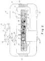
- Fig. 2 is a sectional view of a magnetic disk unit according to an embodiment of the present invention.
- a magnetic disk unit 10 shown in Fig. 2 has such a structure that the movable section 11 also shown in Fig. 1 is disposed at the center, the periphery of the movable section 11 is covered by an inner first outline or housing 31, and the first housing 31 is covered by an outer second outline or housing 41.
- the magnetic disk unit 10 is covered by a double-structure of housings comprising the first housing 31 and the second housing 41.
- This structure makes it possible in conjunction with means for heating and cooling and the like, which will be described later, to place the movable section 11 in a good operating environment.
- the movable section 11 further comprises a temperature sensor 21 and a humidity sensor 22 in addition to the elements referenced in Fig. 1.
- the temperature sensor 21 and the humidity sensor 22 are used for making a measurement of the operational environment of the movable section 11.
- the movable section 11 furthermore comprises a control circuit 23, which will be described in detail in conjunction with Fig. 3, a Peltier element 24 for heating and cooling the movable section 11, and a heater 27 for heating particularly the DCM 26 of the movable section 11.
- the Peltier element 24 has heat sinks 241 at portions outside the second housing 41 to enhance heat radiation efficiency when the movable section 11 is cooled.
- the reason why the heater 27 is disposed at the position of the DCM 26 is that under low temperature there is a possibility that the size of a ball bearing supporting a rotary shaft of the DCM 26 is reduced, and as a result the rotary shaft can displace or run-out. Such run-out of the rotary shaft causes a possibility that there may occur an accident like the magnetic head 14 coming into contact with the magnetic disk 13, and as a result the magnetic disk 13 being damaged, or a possibility that writing or reading errors occur.
- the first housing 31 of the housing double-structure is provided with an air vent 32 permitting a controlled amount of air to be passed through it.
- the first housing 31 is further provided with an aperture 33, which may be closed optionally by a door 34.
- the second housing 41 of the housing double-structure is provided with an air vent 42 permitting a controlled amount of air to be passed through it.
- the second housing 41 is also further provided with an aperture 43, which may be closed optionally by a door 44.
- a housing door switching solenoid 50 is fixed on the second housing 41.
- the housing door switching solenoid 50 is enabled in accordance with an instruction from a control circuit shown in Fig. 3, so that the door 44 is attracted via a driving spring 51 to be opened and thereby open the aperture 43.
- the door 34 is attracted via a coupling spring 52 to be opened and thereby open the aperture 33.
- the driving spring 51 is urged by a further spring (not illustrated) inside the housing door switching solenoid 50, so that the driving spring 51 pushes the door 44 to close the aperture 43.
- the coupling spring 52 pushes the door 34 to close the aperture 33.
- a small-grain silica gel element 53 On a path coupling the two air vents 32 and 42 by the shortest distance in the space formed between the first housing 31 and the second housing 41, there is provided a small-grain silica gel element 53. On the other hand, on a path coupling the two air vents 32 and 42 by the longest distance in the space formed between the first housing 31 and the second housing 41, there is provided a large-grain silica gel element 54.
- the small-grain silica gel element 53 on the path coupling the two air vents 32 and 42 by the short distance
- large-grain silica gel element 54 on the path coupling the two air vents 32 and 42 by the long distance.
- Those silica gel elements 53 and 54 serve to remove humidity from the air passing-through between the two air vents 32 and 42.
- the use of the small-grain silica gel element 53 makes it difficult for the the air to pass through.
- the use of the large-grain silica gel element 54 makes it easy for the air to pass through.
- the air which passes through between the first housing 31 and the second housing 41, mainly flows through the long distance path.
- Formation of an air passage bypass in this manner makes it possible to reduce the interchange of air between the inside of the first housing 31 and the outside of the second housing 41, and makes it easy to maintain an environment suitable for the operation of the disk unit with isolation of the inside from the outside.
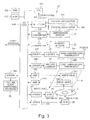
- Fig. 3 is a block diagram of a control circuit of the magnetic disk unit shown in Fig. 2.
- a control circuit 23 comprises a CPU 231, a RAM 232, a ROM 233 and an I/O port 234.
- the control circuit 23 further comprises a 100 MHz crystal oscillator 301 for generating an operational clock of frequency 100 MHz, and a 66 MHz crystal oscillator 302 for generating an operational clock of frequency 66 MHz.
- the two operational clocks are fed to a selector 303.
- One of the two operational clocks, which is selected by the selector 303, is fed to the CPU 231.
- the CPU 231 operates at a speed according to the operational clock frequency fed thereto. Switching of the operational clock by the selector 303 is performed in accordance with an instruction from the I/O port 234 upon receipt of an instruction from the CPU 231.
- the ROM 233 stores therein various sorts of control programs to control the magnetic disk unit.
- the CPU 231 executes the control programs.
- the RAM 232 is used as a working area when the CPU 231 executes the control programs, and also as a temporary storage area for data to be written into the magnetic disk 13 and data read from the magnetic disk 13.
- the I/O port 234 has functions of receiving data from the exterior to transmit the same to the CPU 231, and of outputting an instruction of the CPU 231 to the exterior.
- Signals which are representative of temperature and humidity, from the temperature sensor 21 and the humidity sensor 22 (also shown in Fig. 2), respectively, are converted into digital data by AD converters 235 and 236, respectively.
- the digital data thus converted are fed to the I/O port 234 and then transmitted to the CPU 231.
- the I/O port 234 issues instructions to a driver 237 in accordance with an instruction of the CPU 231, so that the driver 237 turns on or off the heater 27 in accordance with the instruction.
- the I/O port 234 causes the Peltier element 24 to operate in heating or cooling, or to stop its operation in accordance with an instruction of the CPU 231.
- the control circuit 23 further comprises a high-temperature thermostat 304 and a low-temperature thermostat 305.
- a high-temperature thermostat 304 responds, power supply to the heater 27 and the Peltier element 24 is interrupted without an instruction from the CPU 231, to stop the operation of the heater 27 and the Peltier element 24, thereby preventing too much generation of heat.
- the low-temperature thermostat 305 responds, power supply to the Peltier element 24 is interrupted without an instruction from the CPU 231, to stop the operation of the Peltier element 24 thereby preventing too much cooling.
- the I/O port 234 issues instructions to a driver 242 in accordance with an instruction of the CPU 231, so that the driver 242 drives the DCM 26 to drive the magnetic disk 13. Further, the I/O port 234 issues instructions to a driver 241 in accordance with an instruction of the CPU 231, so that the driver 241 drives the VCM 25 to drive the carriage arm 16 shown in Fig. 1 and thereby move the magnetic head 14 provided on the carriage arm 16.
- the magnetic head 14 comprises a WRITE head 141 for performing writing of data into the magnetic disk 13, and a READ head 142 for performing reading of data from the magnetic disk 13.
- the data is transmitted from the I/O port 234 via an amplifier 239 to the WRITE head 141, so that the WRITE head 141 magnetically writes the data into the magnetic disk 13.
- a driver 243 switches the housing door switching solenoid 50 in accordance with an instruction of the I/O port 234 upon receipt of an instruction of the CPU 231.
- the I/O port 234 performs communication with a host system (not illustrated) so that the I/O port 234 receives necessary instructions from the host system and transmits the same to the CPU 231, or makes a necessary report for the host system in accordance with instructions from the CPU 231.
- the driver 242 drives the DCM 26 to rotate the magnetic disk 13 at a constant speed.
- This driver 242 is constructed in such a manner that the driver 242 drives the DCM 26 drawing a distinction between an operation in which the magnetic disk 13 is rotated at a predetermined rotary speed and a current conducted through a winding of the DCM 26 is suppressed, and an operation in which the magnetic disk 13 is rotated at a predetermined rotary speed and as great a current as possible is conducted through a winding of the DCM 26 to promote generation of heat (the latter operation being referred-to as a heat generating operation).
- the carriage arm 16 shown in Fig. 1 when the carriage arm 16 shown in Fig. 1 is not operated, the carriage arm 16 moves to a position rather near the rotary shaft 12 of the magnetic disk 13 and stands-by.
- the driver 241 drives the VCM 25 drawing a distinction between an operation in which, when the carriage arm 16 is in the standby condition, a current conducted through the VCM 25 is stopped or restricted to the minimum value, and an operation in which even when the carriage arm 16 is in the standby condition, a current conducted through the VCM 25 is maintained to drive the VCM 25 in a direction such that the carriage arm 16 further approaches the rotary shaft 12 of the magnetic disk 13 and thereby promotes the generation of heat (the latter operation also being referred-to as a heat generating operation).
- Fig. 4 is a flowchart useful for understanding a program for environment confirmation operation execution, which is related to the present invention, of various sorts of programs to be executed in the CPU in Fig. 3. This program is repeatedly carried out at regular time intervals.
- step a1 the present temperature and humidity are detected from the temperature sensor 21 and the humidity sensor 22 shown in Figs. 2 and 3 respectively, and the following operation is performed in accordance with the detected temperature and humidity.
- step a2 when the temperature is not less than 80-C (step a2), the process goes to a step a3 in which since the normal operating environment is exceeded, the host system is informed that the magnetic disk unit is not operable, and in order to prevent the magnetic disk unit from being damaged the magnetic disk unit is stopped from operating. Further, in some circumstances there is a possibility that the heater and the Peltier element are operated, and thus instructions for stopping the operation of the heater and the Peltier element are issued. Furthermore, there is a possibility that the heat generating operation of the DCM and the VCM is performed, and thus instructions for stopping the heat generating operation of the DCM and the VCM are issued.
- step a4 When the temperature is less than 80°C and not less than 55°C (step a4), the process goes to a step a5 in which the host system is informed that it is now cooling, and the Peltier element 24 performs the cooling operation.
- the heat generating operation of the DCM and the VCM is performed, and thus instructions for stopping the heat generating operation of the DCM and the VCM are issued, and the selector 303 shown in Fig. 2 is switched so that the operational clock of 66 MHz is fed to the CPU 231 to suppress the generation of heat of the control circuit.
- a "writing confirmation necessity" is informed to a writing farm.
- the "writing confirmation necessity" will be described later in conjunction with a flowchart of Fig. 5.
- step a6 When the temperature is less than 55°C and not less than 5°C and the humidity is less than 80% (step a6), the process goes to a step a7, since this represents an environment in which normal operation can be expected without any of heating and cooling. In some circumstances there is a possibility that the heater and the Peltier element are operated, or there is a possibility that the heat generating operation of the DCM and the VCM is performed. Thus in the step a7, the operation of the heater and the Peltier element is stopped, and the heat generating operation of the DCM and the VCM is stopped.
- the selector 303 can select either the operational clock of frequency 100 MHz, or the operational clock of frequency 66 MHz, in accordance with an instruction from the CPU 231 upon receipt of an instruction from the host system.
- the selector 303 is compulsively switched to either one of the operational clock of frequency 100 MHz and the operational clock of frequency 66 MHz independently of an instruction from the host system.
- the step a7 since the normal operational environment does apply, it is permitted to perform switching of the oscillator from the host system.
- step a7 a "writing confirmation no necessity" is informed to the writing arm.
- the housing doors two doors 34 and 44 shown in Fig. 2 are opened, and thus the housing doors are closed.
- step a8 When the temperature is less than 5°C and not less than -10°C or the humidity is not less than 80% (step a8), the process goes to a step a9 in which the host system is informed that the magnetic disk unit is in weak heating, and the heat generating operation of the heater is performed.
- the Peltier element With respect to the Peltier element, in some circumstances there is a possibility that the heat generating operation of the Peltier element is performed, and thus the heat generating operation of the Peltier element is stopped.
- the heat generating operation of the DCM and the VCM is performed.
- the oscillator In order to increase heat generation of the control circuit, the oscillator is changed-over to 100 MHz. A "writing confirmation necessity" is informed to the writing arm, and in order to prevent condensation the housing door is opened.
- step a10 when the temperature is less than -10°C and not less than -30°C (step a10), the process goes to a step a11 in which the host system is informed that the magnetic disk unit is in strong heating, and the heat generating operation of both the heater and the Peltier element is performed.
- the heat generating operation of both the DCM and the VCM is performed, and the oscillator is changed-over to 100 MHz.
- step a10 when the temperature is less than 30°C (step a10), the process goes to a step a12 in which the host system is informed that the magnetic disk unit is not to be operated, and in order to avoid damage of the magnetic disk unit, the operation of the magnetic disk unit is stopped, and operation of the heater and the Peltier element, and heat generating operation of both the DCM and the VCM, are stopped.
- Fig. 5 is a flowchart useful for understanding a writing operation by a writing farm.
- the DCM and the VCM are driven, so that a current conducts through the WRITE head, at the time when the magnetic head reaches a desired position on the magnetic disk, to write data into the magnetic head (a step b1).
- step b2 it is decided as to whether a writing confirmation is necessary or unnecessary.
- the instruction of writing confirmation necessity or non-necessity has been made in the steps a5, a7 and a11.
- step b3 the original data written is saved in the RAM (step b3), and the VCM and the DCM are driven so that a current is read from the READ head to read data, at the time point when the magnetic head reaches the same position as writing for data (a step b4), and the data written in the step b1 (that is, the data saved in the RAM in the step b3) is compared with the data read from the magnetic disk in the step b4 (a step b5). When these data are coincident with one another (a step b6), at that time point, the process is terminated.
- step b6 when it is again decided that these data are not coincident with one another even if the processes of the step b1 to the step b6 are repeated, the process goes via a step b7 to a step b8 in which it is decided that a second rewriting is concerned, and then the process goes to a step b9.
- step b9 the VCM and the DCM are driven so that a current conducts through the WRITE head, at the time point when the magnetic head reaches an alternative different position from the writing positions for the first time and the second time on the magnetic disk, to write data into the alternative position.
- step b10 the written data is saved in the RAM.
- the READ head reads data at the alternative position on the magnetic disk, and then the process returns to the step b5 in which the written data is compared with the read data.
- the writing confirmation and the rewriting are performed.
- This feature makes it possible to improve reliability up to the same degree as in the usual operational environment, and also permits an operation of the magnetic disk unit in a wide range of environments in cooperation with the heating and the cooling.
- Figs. 6 to 10 are views each showing an example of an outline of a double-structure housing or enclosure.
- Fig. 6 shows an example of a housing with a double-structure having an inner first housing 31 and an outer second housing 41, which are provided with air vents 32 and 42 respectively.
- simply providing a housing with a simple double-structure makes it possible to control the environment of the inside of the first housing 31 independently of the environment of the outside of the second housing 41, thereby providing an operable environment.
- Fig. 7 shows an example of a housing with a double-structure, which is the same as the one shown in Fig. 6, but with a partitioning plate 55 being provided.
- the partitioning plate 55 blocks a path coupling the air vent 32 of the first housing 31 with the air vent 42 of the second housing 41 by the shortest distance in the space formed between the first housing 31 and the second housing 41.
- the use of the partitioning plate 55 permits the two air vents 32 and 42 to be coupled with one another only by the longest or bypassed path. This feature makes it possible to further separate the environments of the inside of the first housing 31 and the outside of the second housing 41 from one another.
- Fig. 8 shows an example of a housing with a double-structure, which is the same as the one shown in Fig. 7, but with a silica gel element 56 being provided midway of the path coupling two the air vents 32 and 42 with one another.
- the use of the silica gel element 56 serves to dehumidify the air passing through the bypassed path. This feature makes it possible to further separate the environments of the inside of the first housing 31 and the outside of the second housing 41 from one another.
- Fig. 9 shows an example of a housing with a double-structure, in which the partitioning plate 55 in the structure shown in Fig. 8 is replaced by a small-grain silica gel element 53, and a large-grain silica gel element is placed in the bypassed path.
- this structure serves to dehumidify the air passing through the air vents 32 and 42, and provides a tendency for the air to flow through the longer, bypassed, path.
- Fig. 10 shows an example of a housing with a double-structure, in which silica gel (dehumidifying and moisture absorption agent) or glass wool (heat-insulating agent) occupies the space between the first housing 31 and the second housing 41.
- silica gel dehumidifying and moisture absorption agent
- glass wool heat-insulating agent
- the present invention is not restricted to a magnetic disk unit.
- the present invention is applicable to an information processing apparatus having a magnetic disk unit according to the present embodiments as mentioned above, for example GPS, car navigation system, and a car audio system, the present invention is widely applicable to other types of disk unit and information processing apparatus having the disk unit, for example a magneto-optical disk unit and an information processing apparatus having the magneto-optical disk unit.
Landscapes
- Signal Processing For Digital Recording And Reproducing (AREA)
- Supporting Of Heads In Record-Carrier Devices (AREA)
- Optical Recording Or Reproduction (AREA)
- Cooling Or The Like Of Electrical Apparatus (AREA)
- Moving Of Head For Track Selection And Changing (AREA)
Abstract
Description
Claims (34)
- A disk unit in which an arm having a head thereon can be actuated while a disk is rotated, so that a position of the head is moved with respect to the disk to perform write and read of data to and from the disk by the head, said disk unit comprising:a temperature sensor for detecting temperature; andheating means operable when said temperature sensor detects a temperature which is less than a predetermined first temperature.
- A disk unit according to claim 1, wherein said disk unit further comprises a motor for driving said disk, and said heating means includes means for heating by conducting a current through a fixed phase of said motor.
- A disk unit according to claim 1 or 2, wherein said disk unit further comprises a motor for driving said arm, and said heating means includes means for heating by conducting through that motor a current which is unnecessary for operation of said arm.
- A disk unit according to any preceding claim, wherein said heating means includes a heater.
- A disk unit according to any preceding claim, wherein said heating means includes a Peltier element.
- A disk unit according to any preceding claim, wherein said disk unit further comprises a communication circuit for communication with a host, and when said temperature sensor detects a temperature which is less than the first temperature, said communication circuit informs the host that heating is performed.
- A disk unit according to any preceding claim, wherein said disk unit further comprises a control circuit for controlling an operation of said disk unit, and when said temperature sensor detects a temperature which is less than a predetermined second temperature lower than the first temperature, said control circuit stops the operation of said disk.
- A disk unit according to claim 7, wherein said disk unit further comprises a communication circuit for communication with a host, and when said temperature sensor detects a temperature which is less than the second temperature, said communication circuit informs the host that said disk unit is not operable.
- A disk unit in which an arm having a head thereon can be actuated while a disk is rotated, so that a position of the head is moved with respect to the disk to perform write and read of data to and from the disk by the head, said disk unit comprising:wherein said control circuit is arranged to operate at an operational clock selected in accordance with temperature.a temperature sensor for detecting temperature;a clock generating circuit for generating a plurality of operational clocks which are different in frequency; anda control circuit for controlling an operation of said disk unit in such a manner that upon receipt of any one operational clock from said clock generating circuit, a processing is performed at a processing speed according to a frequency of the received operational clock,
- A disk unit in which an arm having a head thereon can be actuated while a disk is rotated, so that a position of the head is moved with respect to the disk to perform write and read of data to and from the disk by the head, said disk unit comprising:wherein said control circuit is operable to cause said door to open when said temperature sensor detects a temperature which is greater or less than a predetermined temperature.a temperature sensor for detecting temperature;a control circuit for controlling an operation of said disk unit; anda housing having a door which opens and closes in accordance with a control signal,
- A disk unit in which an arm having a head thereon can be actuated while a disk is rotated, so that a position of the head is moved with respect to the disk to perform write and read of data to and from the disk by the head, said disk unit comprising:wherein said access circuit is operable to perform, when writing of data into said disk is performed in a case where said temperature sensor detects a temperature which is out of a predetermined temperature range, a writing confirmation operation for comparing written data with read data through reading data written into said disk.a temperature sensor for detecting temperature; andan access circuit for accessing said disk,
- A disk unit according to claim 11, wherein said access circuit is operable to again write the written data into the same area on said disk and to again read the written data in a case where it is decided by the writing confirmation operation that the written data is not coincident with the read data, and said access circuit is further operable to write the written data into a different area on said disk in a case where it is again decided by the writing confirmation operation that the written data is not coincident with the read data.
- A disk unit in which an arm having a head thereon is actuated while a disk is rotated, so that a position of the head is moved with respect to the disk to perform write and read of data to and from the disk by the head, said disk unit comprising:a temperature sensor for detecting temperature; anda heat generation suppressing means for suppressing generation of heat when said temperature sensor detects a temperature exceeding a predetermined third temperature.
- A disk unit according to claim 13, wherein said heat generation suppressing means includes a Peltier element.
- A disk unit according to claim 13 or 14, wherein said disk unit further comprises a communication circuit for communication with a host, and when said temperature sensor detects a temperature exceeding the third temperature, said communication circuit informs the host that generation of heat is suppressed.
- A disk unit according to claim 13, 14 or 15, wherein said disk unit further comprises a control circuit for controlling an operation of said disk unit, and when said temperature sensor detects a temperature exceeding a predetermined fourth temperature which is higher than the third temperature, said control circuit stops the operation of said disk.
- A disk unit according to claim 16, wherein said disk unit comprises a communication circuit for communication with a host, and when said temperature sensor detects a temperature exceeding the fourth temperature, said communication circuit informs the host that said disk unit is not operable.
- A disk unit in which an arm having a head thereon can be actuated while a disk is rotated, so that a position of the head is moved with respect to the disk to perform write and read of data to and from the disk by the head, said disk unit comprising:a humidity sensor for detecting humidity; andheating means for heating when said humidity sensor detects a humidity exceeding a predetermined humidity.
- A disk unit according to claim 18, wherein said disk unit comprises a motor for driving said disk, and said heating means includes means for heating by conducting a current through a fixed phase of said motor.
- A disk unit according to claim 18 or 19, wherein said disk unit further comprises a motor for driving said arm, and said heating means includes means for heating by conducting through that motor a current which is unnecessary for operation of said arm, at a time of stop of operation of said arm.
- A disk unit according to claim 18, 19 or 20, wherein said heating means includes a heater.
- A disk unit according to claim 18, 19, 20, or 21, wherein said heating means includes a Peltier element.
- A disk unit according to any one of claims 18 to 22, wherein said disk unit further comprises a communication circuit for communication with a host, and when said humidity sensor detects a humidity exceeding the predetermined humidity, said communication circuit informs the host that heating is performed.
- A disk unit in which an arm having a head thereon can be actuated while a disk is rotated, so that a position of the head is moved with respect to the disk to perform write and read of data to and from the disk by the head, said disk unit comprising:wherein said control circuit is arranged to operate at an operational clock selected in accordance with humidity.a humidity sensor for detecting humidity;a clock generating circuit for generating a plurality of operational clocks which are different in frequency; anda control circuit for controlling an operation of said disk unit in such a manner that upon receipt of any one operational clock from said clock generating circuit, a processing is performed at a processing speed according to a frequency of the received operational clock,
- A disk unit in which an arm having a head thereon can be actuated while a disk is rotated, so that a position of the head is moved with respect to the disk to perform write and read of data to and from the disk by the head, said disk unit comprising:wherein said control circuit causes said door to open when said humidity sensor detects a humidity exceeding a predetermined humidity.a humidity sensor for detecting humidity;a control circuit for controlling an operation of said disk unit; anda housing having a door which opens and closes in accordance with a control signal;
- A disk unit in which an arm having a head thereon can be actuated while a disk is rotated, so that a position of the head is moved with respect to the disk to perform write and read of data to and from the disk by the head, said disk unit comprising:wherein said access circuit is operable to perform, when writing of data into said disk is performed in a case where said humidity sensor detects a humidity exceeding a predetermined humidity, a writing confirmation operation for comparing written data with read data through reading data written into said disk.a humidity sensor for detecting humidity; andan access circuit for accessing said disk,
- A disk unit according to claim 26, wherein said access circuit is operable to again write the written data into the same area on said disk and to again read the written data in a case where it is decided by the writing confirmation operation that the written data is not coincident with the read data, and said access circuit is further operable to write the written data into a different area on said disk in a case where it is again decided by the writing confirmation operation that the written data is not coincident with the read data.
- A disk unit in which an arm having a head thereon can be actuated while a disk is rotated, so that a position of the head is moved with respect to the disk to perform write and read of data to and from the disk by the head, said disk unit comprising:a housing double-structure comprising a first housing and a second housing surrounding said first housing.
- A disk unit according to claim 28, wherein a heat-insulating agent is provided between the first housing and the second housing.
- A disk unit according to claim 28 or 29, wherein a dehumidifying agent is provided between the first housing and the second housing.
- A disk unit according to claim 28, wherein each of the first housing and the second housing has an air vent, and said disk unit further comprises means for blocking or relatively lowering a flow of air in an area coupling the air vent of the first housing with the air vent of the second housing, in a space formed between the first housing and the second housing.
- An information processing apparatus having a disk unit for performing reading and writing of information for a disk of the disk unit via an interface, said information processing apparatus comprising:a temperature sensor for detecting temperature; anda control circuit for controlling a heating value of said disk unit in accordance with a temperature detected by said temperature sensor.
- An information processing apparatus according to claim 32, wherein said control circuit is operable to cause a current to conduct through a fixed phase of a motor for rotating a disk of said disk unit, when said temperature sensor detects a temperature which is lower than a predetermined temperature.
- An information processing apparatus according to claim 32 or 33, wherein when said temperature sensor detects a temperature which is out of a predetermined temperature range, said disk unit is operable to inform via said interface that said disk unit is not operable.
Applications Claiming Priority (2)
| Application Number | Priority Date | Filing Date | Title |
|---|---|---|---|
| JP2001044488A JP2002245749A (en) | 2001-02-21 | 2001-02-21 | Disk device and information processing device |
| JP2001044488 | 2001-02-21 |
Publications (3)
| Publication Number | Publication Date |
|---|---|
| EP1235224A2 true EP1235224A2 (en) | 2002-08-28 |
| EP1235224A3 EP1235224A3 (en) | 2003-03-26 |
| EP1235224B1 EP1235224B1 (en) | 2008-09-24 |
Family
ID=18906469
Family Applications (1)
| Application Number | Title | Priority Date | Filing Date |
|---|---|---|---|
| EP01305851A Expired - Lifetime EP1235224B1 (en) | 2001-02-21 | 2001-07-06 | Disk unit and information processing apparatus |
Country Status (5)
| Country | Link |
|---|---|
| US (1) | US6867939B2 (en) |
| EP (1) | EP1235224B1 (en) |
| JP (1) | JP2002245749A (en) |
| KR (1) | KR100722335B1 (en) |
| DE (1) | DE60135900D1 (en) |
Cited By (2)
| Publication number | Priority date | Publication date | Assignee | Title |
|---|---|---|---|---|
| EP1507263A2 (en) | 2003-08-12 | 2005-02-16 | Sony Corporation | Disc recording and/or reproducing apparatus |
| EP1872369A4 (en) * | 2005-04-15 | 2008-03-26 | March Networks Corp | CLOSED ENVIRONMENTAL PARAMETERS CONTROL SYSTEM FOR MOBILE EVENT DATA RECORDER |
Families Citing this family (57)
| Publication number | Priority date | Publication date | Assignee | Title |
|---|---|---|---|---|
| US7191281B2 (en) * | 2001-06-13 | 2007-03-13 | Intel Corporation | Mobile computer system having a navigation mode to optimize system performance and power management for mobile applications |
| US7136247B2 (en) * | 2003-09-30 | 2006-11-14 | Hitachi Global Storage Technologies Netherlands B.V. | Drive temperature self-adjustment for temperature-sensitive measurements |
| US6934107B2 (en) * | 2003-09-30 | 2005-08-23 | Hitachi Global Storage Technologies Netherlands B.V. | Hard disk drive having drive temperature self-adjustment for temperature-sensitive measurements |
| JP2005353163A (en) * | 2004-06-10 | 2005-12-22 | Sony Corp | Recording / reproducing apparatus, recording control method, and program |
| JP2006092645A (en) * | 2004-09-24 | 2006-04-06 | Hitachi Global Storage Technologies Netherlands Bv | Disk drive device |
| KR100674915B1 (en) * | 2004-10-13 | 2007-01-26 | 삼성전자주식회사 | Method and apparatus for driving a regular velocity of a spindle motor |
| JP4470883B2 (en) * | 2005-12-28 | 2010-06-02 | ソニー株式会社 | Disk drive device and imaging device |
| US20070153414A1 (en) * | 2005-12-30 | 2007-07-05 | Michael Sullivan | External cover for controlling the temperature of an internal thermal zone of a hard disk drive |
| US20070165322A1 (en) * | 2005-12-30 | 2007-07-19 | Samsung Electronics Co., Ltd. | Method and apparatus regulating saturation water vapor pressure in a hard disk drive |
| US20070174664A1 (en) * | 2006-01-04 | 2007-07-26 | Ess Data Recovery, Inc. | Data recovery application |
| US8773804B2 (en) * | 2006-01-10 | 2014-07-08 | HGST Netherlands B.V. | Disk drive internal temperature control system |
| JP2007242095A (en) * | 2006-03-06 | 2007-09-20 | Hitachi Global Storage Technologies Netherlands Bv | Data storage device |
| JP2007242085A (en) * | 2006-03-06 | 2007-09-20 | Hitachi Global Storage Technologies Netherlands Bv | Data storage device and disk drive device |
| US7719792B2 (en) * | 2007-01-26 | 2010-05-18 | Samsung Electronics Co., Ltd. | Method and apparatus intelligently adapting to environmental conditions inside and outside a hard disk drive |
| US7813084B1 (en) * | 2007-02-22 | 2010-10-12 | Hutchinson Technology Incorporated | Co-planar shielded write traces for disk drive head suspensions |
| US7542226B2 (en) * | 2007-03-29 | 2009-06-02 | Samsung Electronics Co., Ltd. | Algorithm decoupling altitude effect from temperature/humidity sensor |
| US8549912B2 (en) | 2007-12-18 | 2013-10-08 | Teradyne, Inc. | Disk drive transport, clamping and testing |
| US7996174B2 (en) * | 2007-12-18 | 2011-08-09 | Teradyne, Inc. | Disk drive testing |
| US20090153993A1 (en) * | 2007-12-18 | 2009-06-18 | Teradyne, Inc. | Disk Drive Testing |
| US8102173B2 (en) * | 2008-04-17 | 2012-01-24 | Teradyne, Inc. | Thermal control system for test slot of test rack for disk drive testing system with thermoelectric device and a cooling conduit |
| US7945424B2 (en) * | 2008-04-17 | 2011-05-17 | Teradyne, Inc. | Disk drive emulator and method of use thereof |
| US20110123301A1 (en) * | 2008-04-17 | 2011-05-26 | Scott Noble | Bulk feeding storage devices to storage device testing systems |
| US20090262455A1 (en) | 2008-04-17 | 2009-10-22 | Teradyne, Inc. | Temperature Control Within Disk Drive Testing Systems |
| US8095234B2 (en) * | 2008-04-17 | 2012-01-10 | Teradyne, Inc. | Transferring disk drives within disk drive testing systems |
| US8160739B2 (en) * | 2008-04-17 | 2012-04-17 | Teradyne, Inc. | Transferring storage devices within storage device testing systems |
| US8041449B2 (en) | 2008-04-17 | 2011-10-18 | Teradyne, Inc. | Bulk feeding disk drives to disk drive testing systems |
| US8305751B2 (en) | 2008-04-17 | 2012-11-06 | Teradyne, Inc. | Vibration isolation within disk drive testing systems |
| US8238099B2 (en) * | 2008-04-17 | 2012-08-07 | Teradyne, Inc. | Enclosed operating area for disk drive testing systems |
| US7848106B2 (en) * | 2008-04-17 | 2010-12-07 | Teradyne, Inc. | Temperature control within disk drive testing systems |
| US8117480B2 (en) | 2008-04-17 | 2012-02-14 | Teradyne, Inc. | Dependent temperature control within disk drive testing systems |
| WO2009148942A2 (en) * | 2008-06-03 | 2009-12-10 | Teradyne, Inc. | Processing storage devices |
| US8466699B2 (en) * | 2009-07-15 | 2013-06-18 | Teradyne, Inc. | Heating storage devices in a testing system |
| US7957093B2 (en) * | 2009-07-15 | 2011-06-07 | Seagate Technology Llc | Recording head with current controlled gamma ratio |
| US7920380B2 (en) | 2009-07-15 | 2011-04-05 | Teradyne, Inc. | Test slot cooling system for a storage device testing system |
| US7995349B2 (en) | 2009-07-15 | 2011-08-09 | Teradyne, Inc. | Storage device temperature sensing |
| US8547123B2 (en) * | 2009-07-15 | 2013-10-01 | Teradyne, Inc. | Storage device testing system with a conductive heating assembly |
| US8628239B2 (en) | 2009-07-15 | 2014-01-14 | Teradyne, Inc. | Storage device temperature sensing |
| US8116079B2 (en) | 2009-07-15 | 2012-02-14 | Teradyne, Inc. | Storage device testing system cooling |
| US8687356B2 (en) | 2010-02-02 | 2014-04-01 | Teradyne, Inc. | Storage device testing system cooling |
| US9779780B2 (en) | 2010-06-17 | 2017-10-03 | Teradyne, Inc. | Damping vibrations within storage device testing systems |
| US8687349B2 (en) | 2010-07-21 | 2014-04-01 | Teradyne, Inc. | Bulk transfer of storage devices using manual loading |
| US9001456B2 (en) | 2010-08-31 | 2015-04-07 | Teradyne, Inc. | Engaging test slots |
| CN102681571B (en) * | 2011-03-15 | 2015-02-04 | 神基科技股份有限公司 | Heating circuit, electronic device and method for entering working mode in low temperature environment |
| US9459312B2 (en) | 2013-04-10 | 2016-10-04 | Teradyne, Inc. | Electronic assembly test system |
| US9007882B1 (en) * | 2013-07-31 | 2015-04-14 | Seagate Technology Llc | Heater to keep reader head in stable temperature range |
| US10725091B2 (en) | 2017-08-28 | 2020-07-28 | Teradyne, Inc. | Automated test system having multiple stages |
| US10845410B2 (en) | 2017-08-28 | 2020-11-24 | Teradyne, Inc. | Automated test system having orthogonal robots |
| US10948534B2 (en) | 2017-08-28 | 2021-03-16 | Teradyne, Inc. | Automated test system employing robotics |
| US11226390B2 (en) | 2017-08-28 | 2022-01-18 | Teradyne, Inc. | Calibration process for an automated test system |
| US10983145B2 (en) | 2018-04-24 | 2021-04-20 | Teradyne, Inc. | System for testing devices inside of carriers |
| US10775408B2 (en) | 2018-08-20 | 2020-09-15 | Teradyne, Inc. | System for testing devices inside of carriers |
| US11754596B2 (en) | 2020-10-22 | 2023-09-12 | Teradyne, Inc. | Test site configuration in an automated test system |
| US11953519B2 (en) | 2020-10-22 | 2024-04-09 | Teradyne, Inc. | Modular automated test system |
| US11754622B2 (en) | 2020-10-22 | 2023-09-12 | Teradyne, Inc. | Thermal control system for an automated test system |
| US11899042B2 (en) | 2020-10-22 | 2024-02-13 | Teradyne, Inc. | Automated test system |
| US11867749B2 (en) | 2020-10-22 | 2024-01-09 | Teradyne, Inc. | Vision system for an automated test system |
| US12007411B2 (en) | 2021-06-22 | 2024-06-11 | Teradyne, Inc. | Test socket having an automated lid |
Family Cites Families (16)
| Publication number | Priority date | Publication date | Assignee | Title |
|---|---|---|---|---|
| JPS57205875A (en) | 1981-06-10 | 1982-12-17 | Fujitsu Ltd | Magnetic disk device |
| JPS62188035A (en) * | 1986-02-13 | 1987-08-17 | Toshiba Corp | Condensed dew removing device for optical pickup |
| US4980786A (en) * | 1988-11-14 | 1990-12-25 | Maxtor Corporation | Method and apparatus for improved thermal isolation and stability of disk drives |
| JPH0391185A (en) | 1989-08-31 | 1991-04-16 | Nec Corp | Magnetic disk device |
| US5115225A (en) | 1990-11-13 | 1992-05-19 | Compaq Computer Corporation | Disk drive unit overheating warning system |
| DE4103030A1 (en) * | 1991-02-01 | 1992-08-06 | Thomson Brandt Gmbh | MAGNETIC TAPE DEVICE WITH A HEAD DRUM |
| JPH05109261A (en) * | 1991-10-17 | 1993-04-30 | Nec Ibaraki Ltd | Magnetic disk device |
| JPH05174565A (en) | 1991-12-24 | 1993-07-13 | Nec Gumma Ltd | Hard disc environment managing system |
| JP2902921B2 (en) * | 1993-12-02 | 1999-06-07 | 富士通株式会社 | Disk device temperature detection / control method |
| JP2867911B2 (en) * | 1994-08-16 | 1999-03-10 | 日本電気株式会社 | Magnetic disk drive |
| US6046871A (en) * | 1997-03-31 | 2000-04-04 | Seagate Technology, Inc. | Magnetic recording head slider with piezoelectric sensor for measuring slider to disc interference levels |
| JPH10320724A (en) * | 1997-05-19 | 1998-12-04 | Sony Corp | Recording and playback device |
| US6335843B2 (en) * | 1997-05-23 | 2002-01-01 | Sony Corporation | Recording medium driving device |
| JP3271181B2 (en) * | 1998-11-09 | 2002-04-02 | インターナショナル・ビジネス・マシーンズ・コーポレーション | Disk drive device, disk drive error recovery method, and disk drive control device |
| JP2000310607A (en) | 1999-04-27 | 2000-11-07 | Sony Precision Technology Inc | Dewing foretelling apparatus |
| US6385007B1 (en) * | 2000-08-29 | 2002-05-07 | International Business Machines Corporation | Heat dissipation system of magnetic recording disk |
-
2001
- 2001-02-21 JP JP2001044488A patent/JP2002245749A/en active Pending
- 2001-06-25 US US09/888,896 patent/US6867939B2/en not_active Expired - Fee Related
- 2001-07-06 DE DE60135900T patent/DE60135900D1/en not_active Expired - Fee Related
- 2001-07-06 EP EP01305851A patent/EP1235224B1/en not_active Expired - Lifetime
- 2001-07-19 KR KR1020010043417A patent/KR100722335B1/en not_active Expired - Fee Related
Cited By (5)
| Publication number | Priority date | Publication date | Assignee | Title |
|---|---|---|---|---|
| EP1507263A2 (en) | 2003-08-12 | 2005-02-16 | Sony Corporation | Disc recording and/or reproducing apparatus |
| EP1507263A3 (en) * | 2003-08-12 | 2008-05-28 | Sony Corporation | Disc recording and/or reproducing apparatus |
| US7526188B2 (en) | 2003-08-12 | 2009-04-28 | Sony Corporation | Disc recording and/or reproducing apparatus for use in an image pickup device |
| EP1872369A4 (en) * | 2005-04-15 | 2008-03-26 | March Networks Corp | CLOSED ENVIRONMENTAL PARAMETERS CONTROL SYSTEM FOR MOBILE EVENT DATA RECORDER |
| US7703291B2 (en) | 2005-04-15 | 2010-04-27 | March Networks Corporation | Contained environmental control system for mobile event data recorder |
Also Published As
| Publication number | Publication date |
|---|---|
| KR100722335B1 (en) | 2007-05-28 |
| EP1235224A3 (en) | 2003-03-26 |
| DE60135900D1 (en) | 2008-11-06 |
| US20020114095A1 (en) | 2002-08-22 |
| KR20020068451A (en) | 2002-08-27 |
| JP2002245749A (en) | 2002-08-30 |
| US6867939B2 (en) | 2005-03-15 |
| EP1235224B1 (en) | 2008-09-24 |
Similar Documents
| Publication | Publication Date | Title |
|---|---|---|
| EP1235224B1 (en) | Disk unit and information processing apparatus | |
| KR100589577B1 (en) | Magnetic disk device and control method thereof | |
| JP2005050519A (en) | Voice coil motor control circuit and method | |
| US6433948B1 (en) | Process management method using servo track writer | |
| KR100699893B1 (en) | Hybrid disk drive and data control method of hybrid disk drive | |
| EP0704090A1 (en) | Passive non-contact magnetic latch | |
| US20020034040A1 (en) | Magnetic disk apparatus | |
| US20080174902A1 (en) | Hard disk drive apparatus to control flying height of magnetic head and method thereof | |
| US7375917B1 (en) | Idle seek calibration method for magnetic disk drive and magnetic disk drive with an intermission calibration | |
| US6927931B2 (en) | Magnetic disk drive and method of controlling the same | |
| JPH0348589B2 (en) | ||
| US8355220B2 (en) | Upstream spoiler with integrated crash stop | |
| KR100494609B1 (en) | Controller for information recording and reproducing device and control method for the information recording and reproducing device | |
| US6282052B1 (en) | Method and apparatus for determination of disc drive structural response during typical operations | |
| US7581123B2 (en) | Recording media drive provided with a connecting pin for supply of 3.3V | |
| WO2003021303A3 (en) | Optical disk drive actuator assembly | |
| JP2007066487A (en) | Data storage device and control method thereof | |
| JPH11353826A (en) | Information recording / reproducing apparatus and latch mechanism used therein | |
| JP2003141702A (en) | Disk storage and write control method | |
| US6738217B2 (en) | Method and apparatus for controlling access to disk upon detection of condensation | |
| JPH05205285A (en) | Optical information processing device and system | |
| US20070274000A1 (en) | Disk drive, method for controlling the same, and method for manufacturing the same | |
| US7362539B2 (en) | Disk drive and method of controlling the same | |
| JPH0612856A (en) | Optical disk device | |
| JP2002109855A (en) | Fixed magnetic disk unit |
Legal Events
| Date | Code | Title | Description |
|---|---|---|---|
| PUAI | Public reference made under article 153(3) epc to a published international application that has entered the european phase |
Free format text: ORIGINAL CODE: 0009012 |
|
| AK | Designated contracting states |
Kind code of ref document: A2 Designated state(s): AT BE CH CY DE DK ES FI FR GB GR IE IT LI LU MC NL PT SE TR |
|
| AX | Request for extension of the european patent |
Free format text: AL;LT;LV;MK;RO;SI |
|
| PUAL | Search report despatched |
Free format text: ORIGINAL CODE: 0009013 |
|
| 17P | Request for examination filed |
Effective date: 20021211 |
|
| AK | Designated contracting states |
Kind code of ref document: A3 Designated state(s): AT BE CH CY DE DK ES FI FR GB GR IE IT LI LU MC NL PT SE TR Designated state(s): AT BE CH CY DE DK ES FI FR GB GR IE IT LI LU MC NL PT SE TR |
|
| AX | Request for extension of the european patent |
Extension state: AL LT LV MK RO SI |
|
| AKX | Designation fees paid |
Designated state(s): DE FR GB |
|
| 17Q | First examination report despatched |
Effective date: 20040121 |
|
| GRAP | Despatch of communication of intention to grant a patent |
Free format text: ORIGINAL CODE: EPIDOSNIGR1 |
|
| GRAS | Grant fee paid |
Free format text: ORIGINAL CODE: EPIDOSNIGR3 |
|
| GRAA | (expected) grant |
Free format text: ORIGINAL CODE: 0009210 |
|
| AK | Designated contracting states |
Kind code of ref document: B1 Designated state(s): DE FR GB |
|
| REG | Reference to a national code |
Ref country code: GB Ref legal event code: FG4D |
|
| REF | Corresponds to: |
Ref document number: 60135900 Country of ref document: DE Date of ref document: 20081106 Kind code of ref document: P |
|
| PLBE | No opposition filed within time limit |
Free format text: ORIGINAL CODE: 0009261 |
|
| STAA | Information on the status of an ep patent application or granted ep patent |
Free format text: STATUS: NO OPPOSITION FILED WITHIN TIME LIMIT |
|
| 26N | No opposition filed |
Effective date: 20090625 |
|
| GBPC | Gb: european patent ceased through non-payment of renewal fee |
Effective date: 20090706 |
|
| REG | Reference to a national code |
Ref country code: FR Ref legal event code: ST Effective date: 20100331 |
|
| PG25 | Lapsed in a contracting state [announced via postgrant information from national office to epo] |
Ref country code: FR Free format text: LAPSE BECAUSE OF NON-PAYMENT OF DUE FEES Effective date: 20090731 |
|
| PG25 | Lapsed in a contracting state [announced via postgrant information from national office to epo] |
Ref country code: GB Free format text: LAPSE BECAUSE OF NON-PAYMENT OF DUE FEES Effective date: 20090706 |
|
| PG25 | Lapsed in a contracting state [announced via postgrant information from national office to epo] |
Ref country code: DE Free format text: LAPSE BECAUSE OF NON-PAYMENT OF DUE FEES Effective date: 20100202 |