EP1235122A1 - Portable object with means for activating an electronic function and command procedure for such an electronic function - Google Patents
Portable object with means for activating an electronic function and command procedure for such an electronic function Download PDFInfo
- Publication number
- EP1235122A1 EP1235122A1 EP02075395A EP02075395A EP1235122A1 EP 1235122 A1 EP1235122 A1 EP 1235122A1 EP 02075395 A EP02075395 A EP 02075395A EP 02075395 A EP02075395 A EP 02075395A EP 1235122 A1 EP1235122 A1 EP 1235122A1
- Authority
- EP
- European Patent Office
- Prior art keywords
- portable object
- object according
- function
- electronic
- electronic function
- Prior art date
- Legal status (The legal status is an assumption and is not a legal conclusion. Google has not performed a legal analysis and makes no representation as to the accuracy of the status listed.)
- Granted
Links
Images


Classifications
-
- G—PHYSICS
- G04—HOROLOGY
- G04G—ELECTRONIC TIME-PIECES
- G04G21/00—Input or output devices integrated in time-pieces
Abstract
Description
La présente invention concerne un objet portatif tel que, notamment, une pièce d'horlogerie, comprenant des moyens pour l'activation d'une fonction électronique telle qu'une fonction horlogère. La présente invention concerne également un procédé de commande d'une fonction électronique du genre susmentionné.The present invention relates to a portable object such as, in particular, a room timepieces, comprising means for activating an electronic function such as than a watch function. The present invention also relates to a method of control of an electronic function of the aforementioned kind.
De nombreux dispositifs d'entrée de données dans des moyens électroniques destinés à traiter ces données sont déjà connus. Ces dispositifs peuvent comprendre, par exemple un clavier formé d'une pluralité de touches, chacune de ces touches étant associée à une plage sensible sous-jacente d'un capteur qui commande l'entrée d'une donnée associée à la touche en réponse à l'apposition d'un doigt sur cette touche. Un clavier de ce genre est par exemple décrit dans la demande de brevet européen EP-A-0 674 247 au nom de la Demanderesse dans laquelle il est associé à une montre pour en commander diverses fonctions comme la mise à l'heure ou bien l'enclenchement et le déclenchement d'un chronomètre. Lorsqu'il équipe une montre, un tel clavier permet avantageusement de remplacer les boutons-poussoirs habituels.Numerous data entry devices in electronic means intended to process this data are already known. These devices can include, for example a keyboard formed by a plurality of keys, each of these keys being associated with an underlying sensitive range of a sensor which controls the input of data associated with the key in response to the affixing of a finger on this touch. A keyboard of this kind is for example described in the patent application European EP-A-0 674 247 in the name of the Applicant in which it is associated with a watch to control various functions such as setting the time or starting and starting a stopwatch. When he equips a watch, such a keyboard advantageously makes it possible to replace the usual push buttons.
Les touches des claviers incorporés dans des montres sont constituées par des capteurs tactiles de différents types, par exemple piézosensible, photosensible, résistif ou bien encore capacitif. Dans ce dernier cas, la plage sensible de chaque capteur peut être constituée par une électrode transparente formée sur la face intérieure de la glace. En posant un doigt sur une plage de la surface extérieure de cette glace qui fait face à l'électrode, on forme un condensateur électrique entre ce doigt et l'électrode qui sont séparés par le diélectrique que constitue la glace de la montre. Un circuit électronique sensible à la capacité de ce condensateur repère l'électrode mise en jeu par l'apposition du doigt et en déduit le caractère ou l'opération ainsi sélectionné pour l'une ou l'autre des applications mentionnées ci-dessus.The keys of the keyboards incorporated in watches consist of touch sensors of different types, for example piezosensitive, photosensitive, resistive or even capacitive. In the latter case, the sensitive range of each sensor can consist of a transparent electrode formed on the face interior of the ice. By placing a finger on a range of the outer surface of this ice facing the electrode, we form an electric capacitor between this finger and the electrode which are separated by the dielectric that constitutes the ice of the shows. An electronic circuit sensitive to the capacity of this reference capacitor the electrode brought into play by affixing the finger and deducing therefrom the character or the operation thus selected for one or other of the applications mentioned above.
Comme on l'a déjà dit, l'un des avantages essentiel des claviers à touches tactiles réside dans le fait que de tels claviers, lorsqu'ils équipent des objets portatifs de petites dimensions tels que, en particulier, une montre-bracelet, permettent de s'affranchir des boutons-poussoirs dont les montres sont habituellement munies. Ceci permet, on le comprendra aisément, de réduire sensiblement les coûts de fabrication de telles montres, et de garantir une excellente étanchéité de ces dernières.As already mentioned, one of the essential advantages of keyboards touchscreen is that such keyboards, when fitted to portable objects small dimensions such as, in particular, a wristwatch, allow get rid of the push buttons with which watches are usually fitted. This allows, it will be easily understood, to significantly reduce manufacturing costs such watches, and to guarantee an excellent water resistance of the latter.
Une montre comprenant des moyens de commande formés par un ensemble de capteurs tactiles présente cependant plusieurs inconvénients. L'un de ces inconvénients réside dans le fait que les touches tactiles sont très sensibles au toucher. Il suffit ainsi que l'utilisateur de la montre effleure involontairement l'une des touches du clavier pour qu'aussitôt le caractère ou l'opération correspondant à cette touche soit sélectionné et activé par le circuit électronique de traitement des données.A watch comprising control means formed by an assembly touch sensors has several drawbacks, however. One of these disadvantages is that the touch keys are very sensitive to to touch. It is sufficient for the user of the watch to inadvertently touch one of the keyboard keys so that immediately the character or the operation corresponding to this key is selected and activated by the electronic data processing circuit.
D'autre part, il est nécessaire que les capteurs tactiles soient constamment alimentés par un courant électrique pour pouvoir être utilisés le moment venu, ce qui pose d'évidents problèmes de consommation électrique, d'autant plus importants que les claviers à touches tactiles dont il est question ici sont tout particulièrement destinés à équiper des objets qui sont de petites dimensions et qui ont donc des réserves d'énergie limitées.On the other hand, it is necessary that the touch sensors are constantly powered by an electric current to be used when the time comes, which poses obvious problems of electricity consumption, all the more important as the touch-sensitive keyboards discussed here are particularly intended to equip objects which are of small dimensions and which therefore have limited energy reserves.
Une des fonctions d'une pièce d'horlogerie qui est le plus fréquemment commandée au moyen d'un clavier à touches tactiles est la fonction d'enclenchement ou de déclenchement d'un chronomètre. On s'est malheureusement rendu compte à l'usage qu'une telle technique était particulièrement malcommode et difficile à mettre en oeuvre. En effet, un utilisateur qui souhaite, par exemple, chronométrer un évènement sportif, doit quitter cet événement des yeux pour pouvoir solliciter la plage de la glace correspondant à la touche appropriée de commande de démarrage du chronomètre. Il en résulte un chronométrage souvent peu précis et donc insatisfaisant pour l'utilisateur.One of the most frequently used functions of a timepiece controlled by a touch-sensitive keyboard is the switch-on function or to start a stopwatch. Unfortunately, we realized at the use that such a technique was particularly awkward and difficult to put in action. Indeed, a user who wishes, for example, to time a sporting event, must leave this event of the eyes to be able to solicit the beach glass corresponding to the appropriate start control key for the stopwatch. The result is often inaccurate and therefore unsatisfactory timing. for the user.
Enfin, le risque avec une matrice de capteurs tactiles de forte densité de se tromper de capteur et d'activer une touche non désirée est important. On conçoit, en effet, que la surface de l'empreinte d'un doigt n'est pas très petite par rapport à celle d'un verre de montre, lui-même limité notamment quand il s'agit d'une montre-bracelet. Il est donc difficile de poser le doigt sur le verre de montre au-dessus de l'électrode désirée, sans influencer du même coup les électrodes adjacentes. Pour identifier alors, parmi les électrodes influencées, celle qui était visée, les moyens électroniques incorporés à la montre doivent développer des stratégies d'identification complexes.Finally, the risk with a matrix of high density tactile sensors fooling the sensor and activating an unwanted key is important. We conceive, in effect, that the surface of the fingerprint is not very small compared to that a watch glass, itself limited in particular when it is a wristwatch. It is therefore difficult to put your finger on the watch glass above the desired electrode, without at the same time influencing the adjacent electrodes. For then identify, among the influenced electrodes, the one that was targeted, the means incorporated in the watch must develop identification strategies complex.
La présente invention a pour but de remédier aux problèmes et inconvénients ci-dessus ainsi qu'à d'autres encore en proposant un objet portatif comprenant des moyens permettant notamment de sélectionner la fonction électronique recherchée sans risque de se tromper ou d'activer involontairement une fonction électronique non souhaitée.The object of the present invention is to remedy the problems and drawbacks above as well as to others by proposing a portable object comprising means making it possible in particular to select the electronic function sought without risk of being mistaken or inadvertently activating an electronic function not desired.
A cet effet, la présente invention concerne un objet portatif tel que, notamment, une pièce d'horlogerie, comportant des moyens pour la commande d'au moins une fonction électronique telle qu'une fonction horlogère, ces moyens de commande comprenant au moins une touche tactile pour effectuer la sélection de la fonction électronique recherchée, un circuit électronique de traitement des données repérant la touche tactile mise en jeu et en déduisant un caractère ou une opération ainsi sélectionné, caractérisé en ce que les moyens de commande comprennent en outre une jauge de contrainte permettant de confirmer la sélection de la fonction électronique recherchée et/ou d'activer cette fonction électronique, la confirmation et/ou l'activation de ladite fonction électronique étant effectuée par application d'une pression sur l'objet portatif sous l'effet de laquelle la jauge de contrainte génère un signal de commande qui va être appliqué au circuit électronique de traitement des données, ledit objet portatif pouvant également comprendre des moyens aptes à émettre un signal sonore pour indiquer à un utilisateur que la fonction souhaitée à bien été enclenchée.To this end, the present invention relates to a portable object such as, in particular, a timepiece, comprising means for controlling at least minus an electronic function such as a watch function, these means of command comprising at least one touch key for selecting the electronic function sought, an electronic data processing circuit identifying the touch key in play and deducing a character or an operation thus selected, characterized in that the control means include in addition to a strain gauge to confirm the selection of the function electronics sought and / or activate this electronic function, confirmation and / or the activation of said electronic function being carried out by application of a pressure on the portable object under the effect of which the strain gauge generates a control signal which will be applied to the electronic circuit for processing data, said portable object can also include means capable of beep to indicate to a user that the desired function is has been properly engaged.
Grâce à ces caractéristiques, il n'est plus nécessaire d'alimenter en permanence les touches des claviers. Lorsque l'utilisateur pose un doigt sur l'un des capteurs tactiles du clavier correspondant au caractère ou à l'opération qu'il souhaite effectuer, il pèse simultanément avec son doigt sur l'objet portatif. Détectant l'application d'une pression sur l'objet portatif, la jauge de contrainte génère classiquement un signal électrique qui va être appliqué à un circuit électronique de traitement des données correspondant aux différentes fonctions de l'objet portatif. Ce circuit de commande va alors mettre les touches tactiles du clavier sous tension, repérer celle des touches tactiles mise en jeu par l'apposition du doigt de l'utilisateur, et déduire le caractère ou l'opération sélectionné pour l'une ou l'autre des applications qu'il est à même de gérer.Thanks to these characteristics, it is no longer necessary to supply permanently the keys of the keyboards. When the user places a finger on one of the keyboard touch sensors corresponding to the desired character or operation perform, he weighs simultaneously with his finger on the portable object. detecting applying pressure to the portable object, the strain gauge generates conventionally an electrical signal which will be applied to an electronic circuit of processing of data corresponding to the different functions of the portable object. This control circuit will then turn on the touch keys of the keyboard, identify that of the tactile keys brought into play by affixing the user's finger, and deduce the character or operation selected for one or other of the applications that he can manage.
De même, le risque de voir l'utilisateur activer involontairement une fonction en effleurant par inadvertance une touche du clavier est évité. En effet, le caractère ou l'opération correspondant à la touche du clavier sur laquelle l'utilisateur a posé son doigt ne sera pas sélectionné aussi longtemps que ledit utilisateur n'aura pas également exercé une pression sur l'objet portatif pour confirmer son choix.Likewise, the risk of the user inadvertently activating a function in inadvertently touching a key on the keyboard is avoided. Indeed, the character or the operation corresponding to the key on the keyboard on which the user has placed his finger will not be selected until said user has also exerted pressure on the portable object to confirm its choice.
Cette dernière disposition se révèle particulièrement avantageuse notamment dans le cas particulier où l'utilisateur souhaite utiliser la fonction de chronométrage. Ayant préalablement posé son doigt sur celle des touches tactiles qui va lui permettre d'enclencher le chronomètre, l'utilisateur pourra regarder attentivement l'événement, par exemple sportif, qu'il veut chronométrer, puis exercer une pression sur l'objet portatif pour démarrer le comptage au moment opportun, sans quitter l'événement des yeux.This latter arrangement is particularly advantageous, in particular in the particular case where the user wishes to use the timing function. Having previously placed his finger on that of the tactile keys which will allow him to start the stopwatch, the user can watch the event carefully, for example sportsman, that he wants to time, then exert a pressure on the object portable to start counting at the right time, without leaving the event eyes.
La présente invention concerne également un procédé de commande d'au moins une fonction électronique telle qu'une fonction horlogère d'un objet portatif du genre susdécrit, comprenant l'étape qui consiste à sélectionner la fonction électronique recherchée par application d'un doigt sur la touche tactile associée à ladite fonction, caractérisé en ce qu'il comprend en outre l'étape qui consiste à exercer une contrainte mécanique sur l'objet portatif pour confirmer la sélection de ladite fonction électronique recherchée et/ou activer cette fonction et, le cas échéant, à produire un signal sonore pour indiquer à un utilisateur que la fonction souhaitée a bien été enclenchée.The present invention also relates to a method for controlling at least minus an electronic function such as a watch function of a portable object of the genre described above, including the step of selecting the function electronics sought by applying a finger on the touch key associated with said function, characterized in that it further comprises the step which consists in exert mechanical stress on the portable object to confirm the selection of said electronic function sought and / or activate this function and, where appropriate, to produce an audible signal to indicate to a user that the desired function has has been properly engaged.
D'autres caractéristiques et avantages de la présente invention apparaítront plus clairement à la lecture de la description détaillée qui suit d'un exemple de réalisation de l'objet portatif selon l'invention, cet exemple étant donné à titre purement illustratif et non limitatif, en liaison avec les dessins annexés dans lesquels :
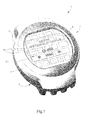
- la figure 1 est une vue générale en perspective d'une pièce d'horlogerie conforme à la présente invention montrant une forme d'agencement des touches d'un clavier en liaison chacune avec un capteur sous-jacent qui commande l'entrée d'une donnée associée à ladite touche;
- la figure 2 est une vue en coupe de la pièce d'horlogerie représentée à la figure 1;
- la figure 3 est une vue à plus grande échelle de la zone entourée d'un cercle sur la figure 2 montrant plus particulièrement la structure d'une touche tactile du clavier;
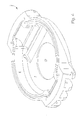
- la figure 4 est une vue en perspective du fond de la boíte de montre représentée à la figure 1;
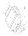
- la figure 5 est une vue en perspective de la pièce d'horlogerie représentée à la figure 1, la glace ayant été enlevée;
- la figure 6 représente un schéma électrique d'un circuit permettant d'utiliser un transducteur piézo-électrique fonctionnant comme générateur de son pour réaliser la fonction d'un bouton-poussoir, et
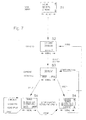
- la figure 7 montre un organigramme d'un exemple de mise en oeuvre du procédé selon l'invention.
- Figure 1 is a general perspective view of a timepiece according to the present invention showing a form of arrangement of the keys of a keyboard each in connection with an underlying sensor which controls the entry of a data associated with said key;
- Figure 2 is a sectional view of the timepiece shown in Figure 1;
- Figure 3 is an enlarged view of the area surrounded by a circle in Figure 2 showing more particularly the structure of a touch key on the keyboard;
- Figure 4 is a perspective view of the bottom of the watch case shown in Figure 1;
- Figure 5 is a perspective view of the timepiece shown in Figure 1, the glass having been removed;
- FIG. 6 represents an electrical diagram of a circuit making it possible to use a piezoelectric transducer operating as a sound generator to perform the function of a push button, and
- FIG. 7 shows a flow diagram of an example of implementation of the method according to the invention.
La présente invention procède de l'idée générale inventive qui consiste à associer à des premiers moyens de commande comprenant un clavier à touches tactiles au moyen desquelles un utilisateur peut sélectionner l'une ou l'autre des fonctions électroniques d'un objet portatif tel que, en particulier, une montre, des seconds moyens de commande comprenant une jauge de contrainte permettant de confirmer la sélection de la fonction électronique recherchée et/ou d'activer cette dernière par application d'une pression mécanique sur l'objet portatif.The present invention proceeds from the general inventive idea which consists in associate with first control means comprising a keypad touchscreen by which a user can select any of the electronic functions of a portable object such as, in particular, a watch, second control means comprising a strain gauge making it possible to confirm the selection of the electronic function sought and / or activate this last by applying mechanical pressure to the portable object.
Une telle combinaison de moyens permet de s'affranchir des problèmes généralement liés à l'emploi de claviers à touches tactiles pour l'introduction des données dans des moyens électroniques de traitement de ces données qui sont, notamment, la grande sensibilité des touches à l'apposition d'un doigt, et le fait que l'utilisateur soit obligé de regarder quelle touche il actionne pour s'assurer que la fonction recherchée a été convenablement sélectionnée.Such a combination of means makes it possible to overcome the problems generally linked to the use of touch-sensitive keyboards for the introduction of data in electronic means of processing these data which are, in particular, the great sensitivity of the keys to the affixing of a finger, and the fact that the user is forced to look at which key he is pressing to ensure that the function sought has been properly selected.
D'autre part, la jauge de contrainte réalise, conformément à la présente invention, la fonction d'un bouton-poussoir. On connaít, en effet, des montres comprenant conjointement un clavier à touches tactiles et un ou plusieurs boutons-poussoirs, le clavier à touches permettant à l'utilisateur de sélectionner la fonction électronique souhaitée, tandis que les boutons-poussoirs permettent d'enclencher ou de déclencher ladite fonction. Cette solution permet d'éviter certains des problèmes décrits plus haut, mais a comme principal inconvénient que les boutons-poussoirs dont la montre est munie sont coûteux à fabriquer et altèrent l'étanchéité de la boíte de ladite montre. En outre, il est nécessaire d'indiquer à l'utilisateur au moyen de symboles d'affichage fixes ou changeants quel bouton-poussoir il faut actionner pour enclencher ou déclencher la fonction désirée, ce qui peut prêter à confusion.On the other hand, the strain gauge realizes, in accordance with this invention, the function of a push button. We know, in fact, watches jointly comprising a keyboard with tactile keys and one or more push-buttons, the keypad allowing the user to select the function desired electronics, while the pushbuttons enable or disable to trigger said function. This solution avoids some of the problems described above, but has the main disadvantage that the pushbuttons which the watch is equipped with are expensive to manufacture and affect the water resistance of the case of said watch. In addition, it is necessary to indicate to the user by means of fixed or changing display symbols which push button to press for turn on or off the desired function, which can be confusing.
On notera dès à présent que, bien que la description qui suit concerne une pièce d'horlogerie et, en particulier, une montre-bracelet, la présente invention n'est pas limitée à une telle pièce d'horlogerie et peut aisément s'appliquer à tout autre objet portatif dans lequel est agencé un clavier à touches tactiles pour la sélection et l'activation d'une pluralité de fonctions électroniques.It will now be noted that, although the description which follows relates to a timepiece and, in particular, a wristwatch, the present invention is not not limited to such a timepiece and can easily be applied to any other portable object in which a keyboard with tactile keys is arranged for selection and activation of a plurality of electronic functions.
On se reportera tout d'abord à la figure 1 sur laquelle est représentée une
pièce d'horlogerie selon l'invention, désignée dans son ensemble par la référence
numérique générale 1. La pièce d'horlogerie 1 comporte de manière classique un
boítier muni d'une carrure 4 et d'un fond 6 qui délimite le boítier 2 dans sa partie
inférieure. Dans l'exemple représenté, la boíte 2 comprend un fond 6 qui est distinct
de la carrure 4. Il va toutefois de soi que la présente invention s'applique de la même
manière à une boíte qui serait monobloc et dont le fond serait fait d'une seule pièce
avec la carrure. Le boítier 2 peut être réalisé, par exemple, en un matériau plastique
selon des techniques d'injection bien connues. La présente invention ne se limite
néanmoins pas au choix d'un tel matériau et le boítier 2 pourra être réalisé en tout
type de matériau adapté aux besoins de l'industrie horlogère tel que, notamment, de
l'acier.We will first refer to Figure 1 on which is represented a
timepiece according to the invention, generally designated by the reference
general digital 1. The
Dans sa partie supérieure, le boítier 2 est délimité par une glace 8 recouvrant
des moyens d'affichage 10 d'une information horaire ou autre. Dans l'exemple
représenté à la figure 1, ces moyens d'affichage 10 se composent d'une cellule
d'affichage matriciel 12 à cristaux liquides. Il s'agit donc de moyens digitaux
d'affichage de données. On pourrait également envisager d'utiliser des moyens
analogiques d'affichage de l'heure comprenant une aiguille des heures, une aiguille
des minutes et une aiguille des secondes qui se déplaceraient au-dessus d'un cadran
formé par une cellule d'affichage à cristaux liquides susceptible, elle aussi, d'afficher
différents types d'informations ou de données. Selon encore une autre variante, les
aiguilles peuvent se déplacer au-dessus d'un cadran conventionnel. Les symboles
représentant les caractères ou les fonctions qui peuvent être sélectionnés par le
porteur de la montre sont alors imprimés, gravés ou encore décalqués sur la glace, la
lunette ou le cadran de la montre.In its upper part, the
Enfin, le boítier 2 comporte à sa périphérie supérieure une lunette 14 qui peut
assurer, le cas échéant, la fixation de la glace 8 sur le boítier 2. La lunette 14 est
montée fixe sur le boítier 2 par exemple par collage ou par soudage aux ultrasons.
Une autre solution qui sera examinée ci-dessous en liaison avec la figure 2 consiste à
fixer la lunette 14 sur le boítier 2 par vissage.Finally, the
Conformément à la présente invention, la pièce d'horlogerie 1 comprend des
moyens de commande de fonctions électroniques telles qu'une fonction horlogère.
Dans l'exemple illustré à la figure 1, ces moyens de commande sont formés par une
pluralité de capteurs tactiles 16, en l'occurrence au nombre de vingt-cinq, disposés
selon une matrice définissant cinq lignes et cinq colonnes de plages sensibles au
toucher qui sont de forme généralement carrée. L'ensemble des plages sensibles 16
est supporté par la glace 8 et s'étend sur la majeure partie de cette glace 8. Selon une
variante de réalisation, on peut également prévoir qu'une partie des plages sensibles
des capteurs tactiles 16 soit située sur la lunette 14 du boítier 2 de la pièce
d'horlogerie 1.According to the present invention, the
La glace 8 occupant la majeure partie de la surface supérieure du boítier 2, la
zone sensible définie par la matrice de capteurs tactiles 16 pour la sélection et
l'activation d'une fonction électronique est relativement grande, sans que ni l'affichage
de l'heure sous une forme analogique ou digitale, ni les dimensions ou l'aspect
extérieur de la pièce d'horlogerie 1 ne s'en trouvent altérés.The
On se réfère maintenant à la figure 2 qui est une vue en coupe de la pièce
d'horlogerie 1 représentée sur la figure 1. La carrure 4 de la pièce d'horlogerie 1
définit une cavité centrale dans laquelle prend place, de manière classique, un
mouvement d'horlogerie électronique 18 porté par un circuit imprimé 20. Ce
mouvement électronique 18 comporte, entre autres, un circuit base de temps, un
circuit diviseur de fréquence alimenté par la base de temps, un circuit de commande
et de traitement des données connecté au circuit diviseur et la cellule d'affichage
matriciel 12 à cristaux liquides commandée par le circuit de commande.We now refer to Figure 2 which is a sectional view of the
Le circuit de commande et de traitement des données remplit des fonctions
variées. Il entretient notamment les oscillations de l'oscillateur à quartz du circuit base
de temps, divise la fréquence du quartz, corrige la marche de la montre et alimente, le
cas échéant, les moteurs et les affichages à cristaux liquides. Il commande
également, en liaison avec les capteurs tactiles 16 et une jauge de contrainte 22 dont
la description va suivre, des fonctions spéciales telles que le quantième, le
chronographe, l'alarme, les fuseaux horaires, et permet de corriger certaines
indications et d'effectuer la mise à l'heure. Il va de soi que pour la sélection et
l'enclenchement ou le déclenchement des fonctions électroniques susmentionnées au
moyen des touches tactiles 16, un circuit électronique de traitement des données
distinct du mouvement électronique 18 de commande de la marche de la pièce
d'horlogerie 1 peut être envisagé.The control and data processing circuit performs functions
varied. It maintains in particular the oscillations of the crystal oscillator of the base circuit
time, divides the frequency of the quartz, corrects the running of the watch and powers the
if applicable, motors and liquid crystal displays. He commands
also, in conjunction with the
Le circuit de commande et de traitement des données est alimenté en courant
par un accumulateur 24 destiné à être rechargé après épuisement. Dans l'exemple
représenté à la figure 2, l'accumulateur 24 est chargé par induction. A cet effet, une
première bobine constitue le primaire du chargeur (non représenté), tandis qu'une
seconde bobine 26, placée dans le circuit de charge de l'accumulateur 24, constitue le
secondaire dudit chargeur. Comme l'accumulateur 24 équipe une pièce d'horlogerie,
on préfère en effet recharger celui-ci par induction plutôt que d'utiliser des contacts
ohmiques pour le connecter au chargeur, ceci afin d'éviter d'altérer l'étanchéité de la
boíte 2 de la pièce d'horlogerie 1. On comprendra néanmoins que le bon
fonctionnement de la pièce d'horlogerie 1 selon l'invention est garanti quel que soit le
procédé de charge de l'accumulateur 24 choisi. On comprendra également que le
circuit de commande et de traitement des données pourrait être alimenté par une pile
non rechargeable.The control and data processing circuit is supplied with current
by an
Comme on peut le voir sur la figure 2, la carrure 4 de la pièce d'horlogerie 1
est montée fixe sur le fond 6 au moyen de vis 28. De même, le circuit imprimé est fixé
sur la carrure 4 au moyen de vis 30. Enfin, la lunette 14 est rendue solidaire de la
carrure 4 par des vis 32. D'autre part, la cellule d'affichage matriciel 12 est reliée
électriquement au circuit imprimé 20 par un connecteur flexible 34.As can be seen in Figure 2, the
La figure 3 est une vue de détail à plus grande échelle de la coupe
représentée sur la figure 2 sur laquelle sont représentées les plages sensibles des
capteurs tactiles 16. Conformément à un mode de réalisation particulier de l'invention,
les capteurs tactiles sont de type capacitif, leurs plages sensibles 16 étant formées
par des électrodes transparentes 36 déposées sur la face inférieure de la glace 8.
Chaque électrode 36 est reliée électriquement au circuit de commande du
mouvement électronique d'horlogerie 18 par l'intermédiaire d'une pluralité de plages
de contact 37 situées sur la périphérie de la glace 8 et de deux connecteurs 38
formés chacun d'une succession de lames verticales conductrices et isolantes, par
exemple en élastomère, qui réalisent le report des contacts électriques depuis la face
inférieure de la glace 8 sur la face supérieure du circuit imprimé 20 (voir figure 5).
L'homme du métier sait comment former des électrodes transparentes à la surface
d'un verre et comment connecter une pluralité de capteurs tactiles capacitifs à une
unité électronique de commande située à l'intérieur d'une boíte de montre.Figure 3 is an enlarged detail view of the section
represented in FIG. 2 in which the sensitive areas of the
L'homme du métier connaít également le principe de fonctionnement de capteurs tactiles capacitifs. C'est pourquoi on n'en rappellera ici que brièvement les grands principes.Those skilled in the art also know the operating principle of capacitive touch sensors. This is why we will only briefly recall here the main principles.
Chacun des capteurs capacitifs est branché en parallèle entre la masse et une entrée du circuit électronique de traitement des données. Le circuit électronique de traitement des données comprend une série d'oscillateurs commandés en tension, la fréquence de chacun de ces oscillateurs variant en fonction de la capacité totale présente entre son entrée et la masse. Si le doigt du porteur de la montre n'est pas posé sur le verre en face d'une électrode particulière, une des armatures du capteur capacitif correspondant n'est par conséquent pas formée. Dans ce cas, la capacité totale présente entre l'entrée et la masse de l'oscillateur est équivalente à la capacité du condensateur parasite associé à ce capteur capacitif. Par contre, lorsque le doigt est posé sur le verre en face de cette électrode, les deux armatures du capteur correspondant sont formées. La capacité totale entre l'entrée et la masse de l'oscillateur est maintenant équivalente à la somme de la capacité du capteur capacitif et de la capacité du capteur parasite. Ainsi, la fréquence d'oscillation de chacun des oscillateurs commandés en tension varie en fonction de la présence ou de l'absence du doigt sur la partie du verre qui est en face de l'électrode associée avec cet oscillateur. Ce changement de fréquence est détecté par le détecteur de fréquence associé à l'oscillateur commandé en tension.Each of the capacitive sensors is connected in parallel between ground and a input of the electronic data processing circuit. The electronic circuit of data processing includes a series of voltage controlled oscillators, the frequency of each of these oscillators varying according to the total capacity present between its input and the ground. If the watch wearer's finger is not placed on the glass in front of a particular electrode, one of the armatures of the sensor corresponding capacitive is therefore not formed. In this case, the capacity total present between the input and the mass of the oscillator is equivalent to the capacity of the parasitic capacitor associated with this capacitive sensor. However, when the finger is placed on the glass opposite this electrode, the two armatures of the sensor correspondent are formed. The total capacity between the input and the mass of the oscillator is now equivalent to the sum of the capacitance of the capacitive sensor and the capacity of the parasitic sensor. So the frequency of oscillation of each of the voltage controlled oscillators varies depending on presence or absence finger on the part of the glass which is opposite the electrode associated with this oscillator. This change in frequency is detected by the frequency detector associated with the voltage controlled oscillator.
Conformément à l'invention, les capteurs tactiles 16 sont associés à la jauge
de contrainte 22 mentionnée ci-dessus. On peut ainsi, au moyen des capteurs tactiles
16, sélectionner une fonction électronique telle qu'une fonction horlogère identifiée par
un caractère transcrit sur la glace 8 de la pièce d'horlogerie 1 ou affichée par la cellule
d'affichage 12, puis confirmer cette sélection et enclencher ou désactiver la fonction
sélectionnée en exerçant une pression sur le boítier 2 de ladite pièce d'horlogerie 1.According to the invention, the
Selon une variante de réalisation, la jauge de contrainte 22 est formée par le
transducteur piézo-électrique qui est classiquement présent dans la plupart des
pièces d'horlogerie et dont le rôle premier est de fonctionner comme générateur de
son pour un dispositif d'alarme. Comme on le voit clairement sur la figure 4, une
cavité 40 est prévue dans le fond 6 de la boíte 2 de la montre 1 pour recevoir, de
manière rigide, le transducteur piézo-électrique 22. Celui-ci est constitué d'un élément
réalisé, par exemple, en une céramique piézo-électrique, et peut avoir, de manière
non limitative, une forme circulaire, son diamètre étant typiquement compris entre dix
et quinze millimètres, et son épaisseur étant de l'ordre de quelques dixièmes de
millimètre. Le transducteur piézo-électrique 22 est collé entre deux électrodes
métalliques supérieure et inférieure (non représentées), l'électrode inférieure étant
reliée rigidement au fond 6 du boítier 2 par tout moyen approprié tel que, par exemple,
par collage. Selon une variante de réalisation, le transducteur piézo-électrique 22 peut
être réalisé sous la forme d'une pastille céramique directement collée sur le fond
métallique de la boíte 2 de la pièce d'horlogerie 1. Selon encore une autre variante de
réalisation, le transducteur 22 est formé par un élément réalisé en une céramique
piézo-électrique et collé sur une pastille métallique qui est elle-même collée sur le
fond de la boíte. Il va de soi que le transducteur piézo-électrique 22 pourrait être fixé
rigidement en un endroit autre que le fond du boítier 2, par exemple contre la carrure
4.According to an alternative embodiment, the
On examine maintenant en liaison avec la figure 6 le schéma du circuit
électrique qui permet d'utiliser le transducteur piézo-électrique 22 fonctionnant comme
générateur de son pour réaliser la fonction d'un bouton-poussoir. Autrement dit,
l'utilisateur de la montre 1, après avoir sélectionné la fonction électronique recherchée
au moyen du clavier à touches tactiles capacitives 16, va confirmer son choix en
exerçant une pression sur le boítier 2 de la pièce d'horlogerie 1. En réponse à cette
sollicitation, le transducteur piézo-électrique 22 se déforme mécaniquement et produit
une tension électrique qui va agir sur la fonction horlogère désirée via le circuit de
commande susdécrit.We now examine in connection with Figure 6 the circuit diagram
electric which allows the use of the
Comme on l'aura compris, le transducteur piézo-électrique 22 qui équipe la
montre 1 selon l'invention est utilisé à la fois comme générateur de son pour le
dispositif d'alarme de la montre 1, et comme moyen pour activer ou désactiver une
fonction électronique telle qu'une fonction horlogère par pression mécanique sur le
boítier 2 de ladite montre 1. Il va néanmoins de soi que ce transducteur 22 peut être
utilisé dans le seul but de confirmer la sélection de la fonction électronique
recherchée. L'autre avantage qu'apporte un capteur piézo-électrique utilisé comme
jauge de contrainte dans le cadre de la présente invention réside dans le fait que ledit
capteur piézo-électrique est apte à émettre un signal sonore en même temps que
l'utilisateur appuie sur le boítier de la pièce d'horlogerie, ce signal sonore indiquant à
l'utilisateur que la fonction horlogère souhaitée a bien été enclenchée.As will be understood, the
Le circuit électrique 42 dont le schéma est représenté à la figure 6 comprend,
branchée sur la sortie de moyens commutateurs comprenant un transistor TR0
alternativement passant et bloqué, une bobine L1. Le transducteur piézo-électrique 22
est raccordé en parallèle sur la bobine L1. Ce circuit électrique 42 reçoit, sur une
connexion d'entrée "a", un signal de commande impulsionnel à créneaux. Depuis la
borne d'entrée "a", ce signal est appliqué à la base du transistor TR0 par l'intermédiaire
d'une résistance R0. Lorsque le transistor TR0 est maintenu passant par l'impulsion du
signal de commande, un courant électrique circule à travers la bobine L1 depuis une
source de tension continue +E, tandis que la connexion "b" du transducteur piézo-électrique
22 est reliée par le transistor TR0 à la masse du circuit électrique 42.The
Au moment où le transistor TR0 passe à l'état bloqué lors du front descendant
de chaque impulsion, toute l'énergie accumulée dans la bobine L1 est transmise aux
bornes du transducteur piézo-électrique 22, chargeant celui-ci à une tension bien
supérieure à la tension d'alimentation +E. Cette impulsion de forte amplitude fournit
au transducteur piézo-électrique 22 l'énergie électrique efficace qui lui est nécessaire
pour fonctionner comme générateur de son. Selon une variante, pour obtenir une
pression acoustique plus élevée, on pourra monter une diode (non représentée) en
série avec la bobine L1. Pour plus de détails concernant ce dernier point, on se
reportera au brevet suisse CH 641 625 au nom de Seiko.When the transistor T R0 goes into the blocked state during the falling edge of each pulse, all the energy accumulated in the coil L 1 is transmitted to the terminals of the
A ce stade de la description, on rappellera que les éléments de circuit qui
viennent d'être décrits servent uniquement à entraíner le transducteur piézo-électrique
22 pour le faire fonctionner comme générateur de son dans un dispositif d'alarme
équipant la pièce d'horlogerie 1 susdécrite. En conséquence, ces différents
composants ne sont nullement nécessaires à la mise en oeuvre de la présente
invention. Ils permettent simplement de démontrer que, grâce aux caractéristiques
particulières de l'invention, un unique transducteur piézo-électrique peut être
avantageusement utilisé à la fois comme générateur de son et comme moyen pour
activer une fonction électronique telle qu'une fonction horlogère d'un objet portatif
comme une montre. Dans ce qui va suivre, on va maintenant s'intéresser à la partie
du circuit électrique 42 qui permet de convertir une pression mécanique en données
pouvant être comprises par le circuit de commande et de traitement de données
équipant la pièce d'horlogerie selon l'invention et permettant de commander les
fonctions horlogères de cette dernière.At this stage of the description, it will be recalled that the circuit elements which
just described are only used to drive the
La pression mécanique exercée par l'utilisateur sur le boítier 2 de la pièce
d'horlogerie 1 se traduit, aux bornes du transducteur piézo-électrique 22, par un signal
électrique. Le circuit électrique 42 comprend un condensateur C1 monté entre la
bobine L1 et le transducteur 22 afin que l'impédance vue par ce dernier soit
suffisamment élevée à basse fréquence.The mechanical pressure exerted by the user on the
Le circuit électrique 42 est complété par un filtre passif 44 monté en parallèle
aux bornes du transducteur piézo-électrique 22. Ce filtre 44 se compose
classiquement d'une résistance R1 et d'un condensateur C2. Comme on le
comprendra aisément, le filtre 40 sert à filtrer le signal haute fréquence présent aux
bornes du transducteur 22 lorsque celui-ci fonctionne comme générateur de son à
une fréquence de l'ordre de 1 kHz, et à éviter que ce signal ne se propage vers les
étages d'amplification et de conversion qui seront décrits ci-après. Par contre, à basse
fréquence, lorsqu'on agit mécaniquement sur le transducteur piézo-électrique 22, le
signal électrique peut passer. Il est ainsi possible d'utiliser simultanément le
transducteur piézo-électrique 22 à la fois comme générateur de son et comme moyen
pour détecter une pression exercée sur la montre 1. En effet, pendant le temps où le
transducteur 22 émet un signal sonore, le signal électrique haute fréquence qui en
résulte est filtré par le filtre passif 44, et ne peut donc pas se propager vers les étages
d'amplification et de conversion du circuit électrique 42, tandis que le signal basse
fréquence résultant de l'application d'une pression sur le boítier 2 de la montre 1 se
superpose au signal haute fréquence et peut passer. Une application intéressante de
ce principe réside dans le fait qu'il est par exemple possible d'interrompre l'émission
du signal sonore correspondant à la fonction alarme de la montre 1 par simple
pression mécanique sur le boítier 2 de cette dernière.The
Le circuit électrique 42 comprend enfin, branchés en parallèle les uns à la
suite des autres aux bornes du circuit passif 44, une résistance R2 de polarisation, un
étage d'amplification 46 et un étage de conversion 48.The
L'étage d'amplification 46 comprend un transistor TR1 dont la source est reliée
à la source de tension continue +E et dont le drain est relié à une résistance R3. La
grille du transistor TR1 est reliée à l'une des extrémités "c" de la résistance R2 dont
l'autre extrémité est reliée à la source de tension continue +E.The
Pour l'étage de conversion 48, on peut envisager tous les inverseurs
disponibles dans les technologies actuelles. A titre d'exemple non limitatif seulement,
l'étage de conversion 48 comprend un inverseur CMOS qui se compose d'un
transistor PMOS TR2 relié à un transistor NMOS TR3. Les grilles de ces deux
transistors TR2 et TR3 sont reliées au point de connexion "d" entre le drain du transistor
TR1 et la résistance R3. Ce point de connexion "d" constitue l'entrée de l'inverseur 48.
Le point de connexion "f" entre les drains des transistors TR2 et TR3 constitue quant à
lui la sortie de l'inverseur.For the
On ne fera pas la démonstration ici car celle-ci est à la portée de l'homme du
métier que, lorsque le transducteur piézo-électrique 22 est au repos, c'est-à-dire
lorsqu'aucune pression n'est exercée sur le boítier 2 de la pièce d'horlogerie 1, le
point de connexion "d" est relié à la masse, tandis que la tension au point de
connexion "f" qui constitue la sortie de l'étage de conversion 48 est égale à +E, de
sorte que l'étage de conversion 48 fonctionne bien comme un inverseur. Inversement,
lorsqu'on exerce une pression mécanique sur le transducteur piézo-électrique 22, le
potentiel au point de connexion "d" qui constitue l'entrée de l'étage de conversion 48
va augmenter et tendre vers +E alors que, dans le même temps, la tension au point
de connexion "f" qui constitue la sortie de l'étage de conversion 48 va passer à zéro.
L'étage de conversion 48 fonctionne donc bien, dans ce cas aussi, comme un
inverseur.We will not do the demonstration here because it is within the reach of the man of the
loom that, when the
La tension au point de sortie "f" de l'étage de conversion 48 passe donc
alternativement de la valeur +E lorsque le transducteur piézo-électrique 22 est au
repos, à une valeur de tension nulle lorsque le transducteur 22 est sollicité. Ce signal
logique est appliqué à l'entrée du circuit de traitement de données du mouvement
électronique d'horlogerie 18 qui, en réponse à ce signal, va commander la fonction
horlogère de la montre 1 sélectionnée par l'utilisateur au moyen des touches tactiles
capacitives 16.The voltage at the output point "f" of the
Comme on va le voir ci-dessous en liaison avec la figure 7, la présente invention s'applique de manière tout à fait remarquable, par exemple à la sélection et à l'activation d'une fonction électronique telle que la fonction de chronométrage dans une pièce d'horlogerie.As will be seen below in connection with FIG. 7, the present invention applies in a most remarkable way, for example in the selection and when activating an electronic function such as the timing function in a timepiece.
La figure 7 illustre le procédé de commande d'une fonction électronique telle
qu'une fonction horlogère conformément à la présente invention. Le procédé
commence à l'étape S1 par la sélection opérée par l'utilisateur de la fonction
électronique qu'il recherche. On suppose ici que cet utilisateur souhaite activer la
fonction de chronométrage de la pièce d'horlogerie 1 selon l'invention. On voit, à
l'étape S1, que l'utilisateur se trouve devant un menu principal lui offrant plusieurs
choix. En apposant l'un de ses doigts sur celles des touches tactiles 16 qui sont
disposées à l'aplomb des flèches qui pointent vers le haut et vers le bas, l'utilisateur
peut faire défiler le menu et entrer dans le mode de chronométrage qui l'intéresse. On
notera que l'inscription "menu" et les flèches orientées vers la gauche et vers la droite
sont des caractères qui peuvent être transcrits sur la glace 8, la lunette 14 ou le
cadran de la pièce d'horlogerie 1, par exemple par gravage ou en utilisant des
décalques.FIG. 7 illustrates the method of controlling an electronic function such
that a watch function in accordance with the present invention. The process
begins at step S1 with the selection made by the user of the function
he is looking for. It is assumed here that this user wishes to activate the
timing function of the
A l'étape S2, l'utilisateur se trouve dans un sous-menu qui correspond à la
fonction de chronométrage qu'il a choisie. On voit à l'étape S2 que le chronomètre est
à zéro et que l'utilisateur dispose d'une touche "start" pour commencer à
chronométrer par exemple un événement sportif. Par application de son doigt sur la
touche "start", l'utilisateur va pouvoir sélectionner la fonction de démarrage du
chronomètre. Le chronomètre ne va pas pour autant démarrer à l'instant où
l'utilisateur aura apposé son doigt sur la touche "start". Il faudra pour cela que
l'utilisateur exerce en outre une pression sur la glace 8 de la pièce d'horlogerie.
L'utilisateur va ainsi dans l'ordre sélectionner la fonction de démarrage du
chronométrage en effleurant la touche tactile capacitive 16 qui recouvre l'inscription
"start", puis observer l'événement sportif qu'il souhaite chronométrer, et enfin, sans
quitter l'événement des yeux, il pourra, par une pression exercée sur la même touche
16 qui recouvre l'inscription "start", démarrer la fonction de chronométrage au moment
où les sportifs s'élanceront. Selon une autre variante de réalisation, la fonction
d'activation du chronomètre est, comme ci-dessus, réalisée par effleurement de la
touche tactile 16 appropriée, puis le chronomètre est démarré par pression sur une
région quelconque de la montre 1, par exemple sur la glace 8 de ladite montre 1 ou
encore sur une zone du boítier 2. Avantageusement, le démarrage du chronomètre
par pression sur la pièce d'horlogerie s'accompagnera de l'émission d'un bref signal
sonore émis par le transducteur piézo-électrique 22 qui confirmera de manière
auditive à l'utilisateur que le chronomètre est bien en marche. Ici aussi, l'utilisateur ne
sera pas obligé de regarder sa montre 1 pour s'assurer que le chronomètre est bien
en marche.In step S2, the user is in a submenu which corresponds to the
timing function he has chosen. We see in step S2 that the stopwatch is
zero and the user has a "start" key to start
timing a sporting event, for example. By applying his finger on the
"start" key, the user will be able to select the start function of the
stopwatch. The stopwatch will not start at the moment when
the user will have affixed his finger on the "start" key. This will require that
the user also exerts pressure on the
Supposons maintenant que la pièce d'horlogerie 1 selon l'invention se trouve
dans le mode chronométrage pour une durée assez longue. Il faut savoir que le mode
chronométrage est un mode de fonctionnement grand consommateur d'énergie car
l'information affichée par la pièce d'horlogerie doit être continuellement rafraíchie. On
peut alors envisager que, le chronomètre étant toujours en marche, la montre 1 se
mette dans un état de veille dans lequel elle affiche, par exemple, l'heure courante,
l'utilisateur conservant néanmoins à tout moment la possibilité d'arrêter le
chronomètre ou de mesurer un temps intermédiaire par effleurement de la touche
tactile 16 appropriée et pression sur cette même touche pour valider la sélection.Let us now suppose that the
A l'étape S3, le chronomètre est en marche et indique le temps écoulé depuis
son démarrage. On voit à l'étape S3 que le nouveau sous-menu qui s'affiche offre à
l'utilisateur le choix entre arrêter le chronomètre au moyen de la touche "stop" ou de
mesurer un temps intermédiaire au moyen de la touche "split". S'il appose son doigt
sur la touche "stop" et qu'il valide sa sélection en appuyant sur la glace 8 à l'endroit de
la touche "stop", l'utilisateur arrive à l'étape S4 où il a le choix entre remettre le
chronomètre à zéro au moyen de la touche "zéro" ou de redémarrer le chronomètre
au moyen de la touche "start". Le redémarrage du chronomètre au moyen de la
touche "start" s'opère de manière analogue à ce qui a été décrit ci-dessus en liaison
avec l'étape S2. L'utilisateur effleure la touche tactile 16 située au-dessus de
l'inscription "start" pour sélectionner la fonction de redémarrage du chronomètre, puis
devra peser sur la pièce d'horlogerie 1 pour effectivement réactiver la fonction de
comptage du temps. Si, au contraire, l'utilisateur pose son doigt sur la touche "split" et
valide sa sélection par pression sur la glace 8 de la pièce d'horlogerie 1, l'utilisateur
arrive à l'étape S5 où le temps intermédiaire mesuré s'affiche. A nouveau, deux choix
s'offrent à l'utilisateur. Soit il effleure la touche "split" et le chronomètre enregistre un
nouveau temps intermédiaire, soit l'utilisateur pose son doigt sur la touche "stop" et il
arrive à l'étape S4 qui a été décrite ci-dessus.In step S3, the stopwatch is running and indicates the time since
its start. We see in step S3 that the new submenu that appears offers to
the user can choose between stopping the stopwatch using the "stop" button or
measure a split time using the "split" key. If he puts his finger
on the "stop" key and confirms his selection by pressing the
On constate donc, à la lecture de ce qui précède, que selon les cas, il suffit à
l'utilisateur d'apposer son doigt sur la touche tactile 16 appropriée du clavier pour
sélectionner et activer une fonction électronique donnée, ou bien qu'il faut non
seulement que l'utilisateur appuie sur une touche tactile 16 pour sélectionner la
fonction désirée, mais encore qu'il exerce une pression sur la pièce d'horlogerie pour
enclencher ladite fonction.It therefore appears, on reading the above, that depending on the case, it suffices to
the user to place his finger on the
Il va de soi que l'invention n'est pas limitée aux modes de réalisation qui
viennent d'être décrits, et que des modifications et des variantes peuvent être
envisagées sans sortir du cadre de la présente invention. En particulier, la jauge de
contrainte 22 peut être un capteur de force résistif dont la résistance électrique varie
lorsqu'une contrainte mécanique est exercée sur la structure munie du capteur de
force résistif. La jauge de contrainte 22 peut également être un dispositif de mesure
qui se caractérise par une variation de la valeur de la capacité d'un condensateur en
fonction de la pression exercée. D'autre part, on peut utiliser d'autres systèmes
d'introduction de données par pression tactile qui utilisent des touches inductives, à
ultrasons ou à infrarouge.It goes without saying that the invention is not limited to the embodiments which
have just been described, and that modifications and variations may be
envisaged without departing from the scope of the present invention. In particular, the
Claims (25)
Priority Applications (1)
| Application Number | Priority Date | Filing Date | Title |
|---|---|---|---|
| EP20020075395 EP1235122B1 (en) | 2001-02-23 | 2002-01-31 | Portable object with means for activating an electronic function and command procedure for such an electronic function |
Applications Claiming Priority (3)
| Application Number | Priority Date | Filing Date | Title |
|---|---|---|---|
| EP01200694A EP1235121A1 (en) | 2001-02-23 | 2001-02-23 | Portable object with means for activating an electronic function and command procedure for such an electronic function |
| EP01200694 | 2001-02-23 | ||
| EP20020075395 EP1235122B1 (en) | 2001-02-23 | 2002-01-31 | Portable object with means for activating an electronic function and command procedure for such an electronic function |
Publications (2)
| Publication Number | Publication Date |
|---|---|
| EP1235122A1 true EP1235122A1 (en) | 2002-08-28 |
| EP1235122B1 EP1235122B1 (en) | 2003-06-11 |
Family
ID=26076840
Family Applications (1)
| Application Number | Title | Priority Date | Filing Date |
|---|---|---|---|
| EP20020075395 Expired - Lifetime EP1235122B1 (en) | 2001-02-23 | 2002-01-31 | Portable object with means for activating an electronic function and command procedure for such an electronic function |
Country Status (1)
| Country | Link |
|---|---|
| EP (1) | EP1235122B1 (en) |
Cited By (4)
| Publication number | Priority date | Publication date | Assignee | Title |
|---|---|---|---|---|
| US7420881B2 (en) | 2003-10-31 | 2008-09-02 | Asulab S.A. | Interactive switching device for a portable electronic apparatus |
| US8824245B2 (en) | 2010-10-25 | 2014-09-02 | Advance Watch Company, Ltd. | Touch screen watch |
| EP2966517A1 (en) | 2014-07-10 | 2016-01-13 | The Swatch Group Research and Development Ltd. | Portable electronic device for displaying information |
| CN113870665A (en) * | 2021-10-09 | 2021-12-31 | 韩福梅 | Probability teaching intelligent control demonstration statistical device and method thereof |
Citations (5)
| Publication number | Priority date | Publication date | Assignee | Title |
|---|---|---|---|---|
| US3777472A (en) * | 1971-03-30 | 1973-12-11 | Citizen Watch Co Ltd | Watch with electronic buzzer |
| FR2350633A1 (en) * | 1976-05-07 | 1977-12-02 | Verneret Jacques | Control system for quartz water digital display - uses membrane in base of watch responding to bending of wrist to turn on display |
| US4444515A (en) * | 1981-05-11 | 1984-04-24 | Clark Lloyd D | Earring watch |
| EP0758107A1 (en) * | 1995-08-07 | 1997-02-12 | HONDA TSUSHIN KOGYO Co., Ltd. | Timer alarm device |
| US5742564A (en) * | 1995-11-29 | 1998-04-21 | Junghans Uhren Gmbh | Timepiece with switch operable by pressing the timepiece glass |
-
2002
- 2002-01-31 EP EP20020075395 patent/EP1235122B1/en not_active Expired - Lifetime
Patent Citations (5)
| Publication number | Priority date | Publication date | Assignee | Title |
|---|---|---|---|---|
| US3777472A (en) * | 1971-03-30 | 1973-12-11 | Citizen Watch Co Ltd | Watch with electronic buzzer |
| FR2350633A1 (en) * | 1976-05-07 | 1977-12-02 | Verneret Jacques | Control system for quartz water digital display - uses membrane in base of watch responding to bending of wrist to turn on display |
| US4444515A (en) * | 1981-05-11 | 1984-04-24 | Clark Lloyd D | Earring watch |
| EP0758107A1 (en) * | 1995-08-07 | 1997-02-12 | HONDA TSUSHIN KOGYO Co., Ltd. | Timer alarm device |
| US5742564A (en) * | 1995-11-29 | 1998-04-21 | Junghans Uhren Gmbh | Timepiece with switch operable by pressing the timepiece glass |
Non-Patent Citations (1)
| Title |
|---|
| PIGUET C ET AL: "NOUVELLES POSSIBILITES D'ENTRER DES DONNEES DANS UNE MONTRE", BULLETIN ANNUEL DE LA SOCIETE SUISSE DE CHRONOMETRIE ET DU LABORATOIRE SUISSE DE RECHERCHES HORLOGERES, SOCIETE SUISSE DE CHRONOMETRIE. NEUCHATEL, CH, vol. 7, no. 4, 1978, pages 499 - 502, XP002034253 * |
Cited By (4)
| Publication number | Priority date | Publication date | Assignee | Title |
|---|---|---|---|---|
| US7420881B2 (en) | 2003-10-31 | 2008-09-02 | Asulab S.A. | Interactive switching device for a portable electronic apparatus |
| US8824245B2 (en) | 2010-10-25 | 2014-09-02 | Advance Watch Company, Ltd. | Touch screen watch |
| EP2966517A1 (en) | 2014-07-10 | 2016-01-13 | The Swatch Group Research and Development Ltd. | Portable electronic device for displaying information |
| CN113870665A (en) * | 2021-10-09 | 2021-12-31 | 韩福梅 | Probability teaching intelligent control demonstration statistical device and method thereof |
Also Published As
| Publication number | Publication date |
|---|---|
| EP1235122B1 (en) | 2003-06-11 |
Similar Documents
| Publication | Publication Date | Title |
|---|---|---|
| JP4252754B2 (en) | Portable object including electronic function operating means and method for controlling the electronic function | |
| EP2884353B1 (en) | Touch-sensitive portable electronic object | |
| EP2473884B1 (en) | Decorative element for a wristwatch | |
| EP0674247B1 (en) | Clock with manual control | |
| CH688498B5 (en) | Timepiece with horometric information by not sound vibrations. | |
| EP3156855B1 (en) | Mechanical wristwatch with an electronic function associated thereto | |
| EP2966517A1 (en) | Portable electronic device for displaying information | |
| EP1235122B1 (en) | Portable object with means for activating an electronic function and command procedure for such an electronic function | |
| EP1207439B1 (en) | Electronic watch with capacitive switches on its cover glass | |
| EP1739511B1 (en) | Method for synchronizing the analog display means and a volatile time counter in a timepiece | |
| US6813223B1 (en) | Portable object such as, in particular, a timepiece, including a piezoelectric transducer for entering data manually | |
| EP1134630B1 (en) | Means for exchanging information with a portable object, in particular a time-piece | |
| EP1235121A1 (en) | Portable object with means for activating an electronic function and command procedure for such an electronic function | |
| EP1128239B1 (en) | Portable object, in particular time piece, incorporating a piezo-electric transducer for manually introducing data | |
| EP1158375B1 (en) | Electronic device for elaborating and displaying information | |
| EP1324162B1 (en) | Manual command means for executing the functions of an electronic watch | |
| EP1154339B1 (en) | Portable electronic device such as a timepiece, provided with a push-button | |
| EP4174586A1 (en) | Timepiece assembly comprising a watch and a system for correcting the time | |
| CH719100A2 (en) | Watchmaker's assembly comprising a watch and a time correction system. | |
| CH708730B1 (en) | Portable electronic touch object. | |
| CH718619A2 (en) | Watch fitted with a control device allowing the stroke of a previously interrupted hand to be restarted. | |
| EP0884663B1 (en) | Watch with tactile reading and setting of horometric functions | |
| CH701750A2 (en) | Casing element e.g. dial, for wrist watch, has electronic device and power supply source that are integrated in casing element in order to form autonomous electronic module, where module is completely independent to movement of wrist watch | |
| CH709014A2 (en) | adjusting device for watch. | |
| EP1324160A1 (en) | Manual command means for executing the functions of an electronic watch |
Legal Events
| Date | Code | Title | Description |
|---|---|---|---|
| PUAI | Public reference made under article 153(3) epc to a published international application that has entered the european phase |
Free format text: ORIGINAL CODE: 0009012 |
|
| 17P | Request for examination filed |
Effective date: 20020214 |
|
| AK | Designated contracting states |
Kind code of ref document: A1 Designated state(s): AT BE CH CY DE DK ES FI FR GB GR IE IT LI LU MC NL PT SE TR |
|
| AX | Request for extension of the european patent |
Free format text: AL;LT;LV;MK;RO;SI |
|
| GRAH | Despatch of communication of intention to grant a patent |
Free format text: ORIGINAL CODE: EPIDOS IGRA |
|
| GRAA | (expected) grant |
Free format text: ORIGINAL CODE: 0009210 |
|
| GRAH | Despatch of communication of intention to grant a patent |
Free format text: ORIGINAL CODE: EPIDOS IGRA |
|
| AKX | Designation fees paid |
Designated state(s): CH DE FR GB IT LI |
|
| AK | Designated contracting states |
Designated state(s): CH DE FR GB IT LI |
|
| PG25 | Lapsed in a contracting state [announced via postgrant information from national office to epo] |
Ref country code: IT Free format text: LAPSE BECAUSE OF FAILURE TO SUBMIT A TRANSLATION OF THE DESCRIPTION OR TO PAY THE FEE WITHIN THE PRESCRIBED TIME-LIMIT;WARNING: LAPSES OF ITALIAN PATENTS WITH EFFECTIVE DATE BEFORE 2007 MAY HAVE OCCURRED AT ANY TIME BEFORE 2007. THE CORRECT EFFECTIVE DATE MAY BE DIFFERENT FROM THE ONE RECORDED. Effective date: 20030611 |
|
| REG | Reference to a national code |
Ref country code: GB Ref legal event code: FG4D Free format text: NOT ENGLISH |
|
| REG | Reference to a national code |
Ref country code: CH Ref legal event code: EP |
|
| REG | Reference to a national code |
Ref country code: IE Ref legal event code: FG4D Free format text: FRENCH |
|
| REF | Corresponds to: |
Ref document number: 60200003 Country of ref document: DE Date of ref document: 20030717 Kind code of ref document: P |
|
| REG | Reference to a national code |
Ref country code: CH Ref legal event code: NV Representative=s name: ICB INGENIEURS CONSEILS EN BREVETS SA |
|
| GBT | Gb: translation of ep patent filed (gb section 77(6)(a)/1977) |
Effective date: 20031018 |
|
| REG | Reference to a national code |
Ref country code: IE Ref legal event code: FD4D |
|
| PLBE | No opposition filed within time limit |
Free format text: ORIGINAL CODE: 0009261 |
|
| STAA | Information on the status of an ep patent application or granted ep patent |
Free format text: STATUS: NO OPPOSITION FILED WITHIN TIME LIMIT |
|
| 26N | No opposition filed |
Effective date: 20040312 |
|
| PGFP | Annual fee paid to national office [announced via postgrant information from national office to epo] |
Ref country code: GB Payment date: 20121224 Year of fee payment: 12 |
|
| GBPC | Gb: european patent ceased through non-payment of renewal fee |
Effective date: 20140131 |
|
| PG25 | Lapsed in a contracting state [announced via postgrant information from national office to epo] |
Ref country code: GB Free format text: LAPSE BECAUSE OF NON-PAYMENT OF DUE FEES Effective date: 20140131 |
|
| REG | Reference to a national code |
Ref country code: FR Ref legal event code: PLFP Year of fee payment: 15 |
|
| REG | Reference to a national code |
Ref country code: FR Ref legal event code: PLFP Year of fee payment: 16 |
|
| REG | Reference to a national code |
Ref country code: CH Ref legal event code: PFUS Owner name: THE SWATCH GROUP RESEARCH AND DEVELOPMENT LTD , CH Free format text: FORMER OWNER: ASULAB S.A., CH |
|
| REG | Reference to a national code |
Ref country code: FR Ref legal event code: PLFP Year of fee payment: 17 |
|
| PGFP | Annual fee paid to national office [announced via postgrant information from national office to epo] |
Ref country code: SI Payment date: 20181231 Year of fee payment: 12 |
|
| PGFP | Annual fee paid to national office [announced via postgrant information from national office to epo] |
Ref country code: DE Payment date: 20181218 Year of fee payment: 18 |
|
| REG | Reference to a national code |
Ref country code: DE Ref legal event code: R119 Ref document number: 60200003 Country of ref document: DE |
|
| PG25 | Lapsed in a contracting state [announced via postgrant information from national office to epo] |
Ref country code: DE Free format text: LAPSE BECAUSE OF NON-PAYMENT OF DUE FEES Effective date: 20200801 Ref country code: FR Free format text: LAPSE BECAUSE OF NON-PAYMENT OF DUE FEES Effective date: 20200131 |
|
| PGFP | Annual fee paid to national office [announced via postgrant information from national office to epo] |
Ref country code: CH Payment date: 20201217 Year of fee payment: 20 |
|
| REG | Reference to a national code |
Ref country code: CH Ref legal event code: PL |