EP1235087A2 - Fiber optic cable assembly and method of making same - Google Patents
Fiber optic cable assembly and method of making same Download PDFInfo
- Publication number
- EP1235087A2 EP1235087A2 EP01126647A EP01126647A EP1235087A2 EP 1235087 A2 EP1235087 A2 EP 1235087A2 EP 01126647 A EP01126647 A EP 01126647A EP 01126647 A EP01126647 A EP 01126647A EP 1235087 A2 EP1235087 A2 EP 1235087A2
- Authority
- EP
- European Patent Office
- Prior art keywords
- fibers
- web
- fiber
- interconnect cable
- composition
- Prior art date
- Legal status (The legal status is an assumption and is not a legal conclusion. Google has not performed a legal analysis and makes no representation as to the accuracy of the status listed.)
- Withdrawn
Links
Images

Classifications
-
- G—PHYSICS
- G02—OPTICS
- G02B—OPTICAL ELEMENTS, SYSTEMS OR APPARATUS
- G02B6/00—Light guides; Structural details of arrangements comprising light guides and other optical elements, e.g. couplings
- G02B6/44—Mechanical structures for providing tensile strength and external protection for fibres, e.g. optical transmission cables
- G02B6/4439—Auxiliary devices
- G02B6/4471—Terminating devices ; Cable clamps
- G02B6/4472—Manifolds
- G02B6/4475—Manifolds with provision for lateral branching
-
- G—PHYSICS
- G02—OPTICS
- G02B—OPTICAL ELEMENTS, SYSTEMS OR APPARATUS
- G02B6/00—Light guides; Structural details of arrangements comprising light guides and other optical elements, e.g. couplings
- G02B6/44—Mechanical structures for providing tensile strength and external protection for fibres, e.g. optical transmission cables
- G02B6/4401—Optical cables
- G02B6/4403—Optical cables with ribbon structure
Definitions
- Fiber optic cables have been developed containing two or more loose optical fibers within a buffer tube.
- the fibers within the buffer tube are free to move in various directions relative to each other, including longitudinally along the lengthwise directions of the fibers.
- Connection of the optical fibers of the cable to an optical device is accomplished with the aid of a connector designed to receive ends of the fibers.
- One type of connector is designed to have the fiber ends inserted into a rear end of the connector and pushed through channels defined in the connector until the end faces of the fibers protrude out an end face of the connector at a front end thereof.
- the fibers are then epoxied in place and cleaved at their ends protruding out from the connector end face, and finally the connector end face and fiber end faces are polished.
- the ability of the optical fibers within the buffer tube to slide relative to each other assists, or at least does not hinder, the assembly of the connector on the ends of the fibers.
- Another type of connector contains pre-polished optical fiber stubs having rear ends located internally within the connector for abutting with the ends of the cable fibers.
- the opposite front ends of the stubs are located proximate the front end face of the connector for mating with another optical device.
- the connector is attached to the cable fiber ends by inserting the fiber ends into the rear end of the connector and sliding the fibers forward until their ends abut the rear ends of the stubs, and then the fibers are clamped into place by operating a cam member of the connector.
- the fiber ends are inserted into the connector they are first prepared by laying them side-by-side on a mechanical cleaver and cleaving them to precisely the same length.
- the optical fiber assembly comprises a plurality of optical fibers arranged parallel to one another such that each optical fiber is closely adjacent to at least one other optical fiber, and a web of material disposed between each pair of adjacent optical fibers and bound to said fibers at opposing surfaces thereof, the web lightly tacking the adjacent fibers together to prevent relative sliding between the fibers along a longitudinal direction thereof and being readily broken when pulling forces are exerted on the fibers away from each other transverse to the longitudinal direction such that the fibers can be separated without the fibers being broken by the pulling forces.
- the fibers are tacked together they are enveloped in a buffer tube that serves to protect the fibers.
- the assembly can then be incorporated into a fiber optic cable.
- the optical fiber assembly is formed by placing a plurality of optical fibers side-by-side and parallel to one another such that adjacent fibers are closely spaced apart, applying a hardenable composition in a fluid state onto the fibers such that the composition fills a space between each pair of adjacent fibers, removing the composition from surfaces of the fibers other than opposing surfaces of adjacent fibers such that all surfaces of the fibers except for said opposing surfaces are substantially free of the composition, and causing the composition to harden, whereby webs of the hardened composition are attached between said opposing surfaces of adjacent fibers so as to bind tha fibers together.
- the fluid composition can be of various types, including but not limited to heat-curable and radiation-curable (e.g., UV-curable) compositions, and can be applied to the fibers by passing the fibers through a bath of the composition.
- the side-by-side fibers can then be passed through an aperture of a tool such that edges of the aperture scrape the composition off the surfaces of the fibers except for the opposing surfaces between which it is desired to form a web.
- the remaining composition between the fibers can then be hardened, such as by heating in the case of a heat-curable composition, or by exposing the composition to radiant energy in the case of a radiation-curable composition.
- the optical fiber assembly is made by coating each of a plurality of optical fibers with a hardenable composition in fluid form, placing the coated optical fibers side-by-side and parallel to one another, pressing adjacent fibers against each other while the composition is still fluid such that the coatings on the fibers meld together to form a web of the composition between the fibers, and causing the composition to harden such that adjacent fibers are bound together by the web of the composition.
- the hardenable composition can comprise a coloring composition that is applied to impart a particular color to the fibers for identification purposes.
- the coloring composition can serve both coloring and binding purposes.
- the composition can be of various types, including but not limited to a solvent-based composition that hardens upon evaporation of the solvent, a heat-curable composition, or a radiation-curable composition.
- the fibers are provided to have a solid coating of a composition that is soluble in a solvent.
- the coating can be a soluble ink for coloring the fibers.
- a quantity of the solvent for the coating composition is applied to at least a portion of the solid coating of each of the fibers so as to cause the composition to become softened and tacky.
- the fibers are then pressed together such that the tacky parts of the coatings of adjacent fibers meld together, and the solvent is allowed or caused to evaporate so that the composition becomes solid again, thus binding the fibers together.
- the fiber optic assembly in accordance with the invention can have the web between fibers formed as a plurality of discrete web sections that are spaced apart in the lengthwise direction of the fibers, i.e., an intermittent web.
- the web whether continuous or intermittent, is strong enough to prevent sliding of one fiber relative to the other, but is weak enough to allow the fibers to be pulled apart with relatively little force such that the optical fibers are not broken. Once pulled apart, the fibers are substantially free of any binding material that would have to be removed prior to cleaving and inserting the fibers into a connector.
- the optical fiber assembly of the invention is different from a conventional optical fiber ribbon in which the fibers are totally enveloped in a matrix of material having a relatively high modulus and hardness, such that the matrix material must be peeled off the fibers before the fibers can be separated from one another.
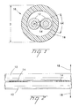
- FIG. 1 depicts a cross-sectional view of an optical fiber assembly 10 in accordance with one preferred embodiment of the invention.
- Assembly 10 includes a pair of optical fibers 12 lightly tacked or bound together by a longitudinally continuous or intermittent colored or non-colored web 14 that is distinct from the outer layer of the optical fibers.
- Fibers 12 are contained within a buffer tube 16 that serves to protect the fibers.
- the outside diameter (OD) of tube 16 is 800 to 2,000 ⁇ m, more preferably about 1,150 ⁇ m with an ID of about 580 ⁇ m.
- Tube 16 can include a water swellable yarn or a filling compound.
- a typical optical fiber 12 includes a silica-based core that is operative to transmit light and is surrounded by a silica-based cladding having a lower index of refraction than the core.
- a soft primary coating surrounds the cladding, and a relatively rigid secondary coating surrounds the primary coating and preferably at least one fiber includes a coloring ink layer as an outermost layer; however, both or neither of the fibers could be colored.
- the OD of a colored fiber is preferably about 255 ⁇ m.
- the height of the web is about 100 to 125 ⁇ m, the width is about 50 ⁇ m or less, and the web subtends an angle ⁇ of about 120° or less, preferably about 60° or less (FIG. 1).
- Web 14 can comprise a meniscus shape.
- Optical fibers 12 can be, for example, single-mode or multi-mode optical fibers made commercially available by Corning Incorporated.
- Web 14 can be formed of various materials. As one example, a thin thread of a curable resin, such as a UV-curable acrylic resin, can be laid between fibers 12 and then cured such that it bonds to the fibers. Other materials can alternatively be used for making web 14, including various types of initially fluid polymers that are solvent-based and solidify upon evaporation of the solvent, polymers that are curable by heating, or polymers that are curable by exposure to radiant energy such as UV radiation.
- web 14 can comprise a small filament coated or impregnated with a resin material. The filament can be a fiber or tension element, for example, an aramid or Zylon material from Toyobo Co. LTD.
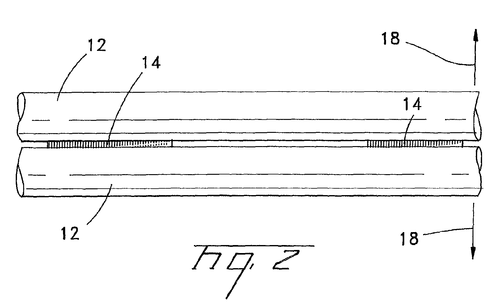
- web 14 must be sufficiently strong to prevent relative sliding motion between fibers 12, yet be weak enough to permit fibers 12 to be easily separated from each other by pulling fibers 12 apart generally along the directions indicated by arrows 18 in FIG. 2, without causing fibers 12 to be broken.
- This separation of fibers 12 can be effected by causing a bond between web 14 and a fiber 12 to break, and/or by causing web 14 to break.
- a preferred fiber-to-fiber spacing is about 245 ⁇ 10 ⁇ m to about 300 ⁇ m ⁇ 10 ⁇ m whether natural (uncolored) or colored fibers are used.
- the outer layers of the fibers may be upcoated to an OD of about 300 to 1000 ⁇ m or more, more preferably about 650 to 800 ⁇ m, therefore the fiber-to-fiber spacing may be up to about 1,000 ⁇ m or more.
- the web 14 can be a continuous web that extends the entire lengths of fibers 12 substantially without interruption.
- web 14 can be in the form of a plurality of discrete web sections 14 that are spaced apart along the fibers. This can result in a savings of material making up web 14 and/or can be used for tailoring the breaking strength of the connections between fibers 12. For example, where the web sections are relatively short in the longitudinal direction of the fibers, making a web section shorter will generally result in less force needed for breaking the web section or its bond with a fiber.
- the amount of force required to break web 14 or its bond with a fiber 12 will generally depend on the cross-sectional area of the portion of web 14 that is subjected to the highest stress when fibers 12 are pulled apart. Adhesion strength is a minimum of about 2 grams/inch as measured by a film test.
- This cross-sectional area is a function of the thickness of web 14, and can also be a function of the longitudinal length of the web when it comprises a discrete web section that is relatively short in the longitudinal direction. That is, if the longitudinal length of web 14 is short enough that substantially the entire length of the web is subjected to essentially the peak stress tending to break the web or its connection with a fiber, the longitudinal length of the web can have an influence on the amount of force needed to break the connection.
- Web 14 can include a benzophenone material for initial UV and/or thermal cure, where curing is done with UV and thermal energy simultaneously or in series.
- ink layers preferably are made without substantial portions of silicone compound for good adhesion between web 14 and the ink layer.
- the elongation to break is about 70% to about 200%.
- the preferred modulus ranges are between about a secant modulus of 25 to 400 MPa at 2.5% strain, more preferably a modulus of about 50 to 300 MPa, and most preferably about 60 MPa.
- a preferred glass transition temperature, based on the tan delta method is about -30 to +70C, more preferably about 20C.
- FIGS. 3-6 A first preferred method for binding fibers together in accordance with the invention is now described with reference to FIGS. 3-6.
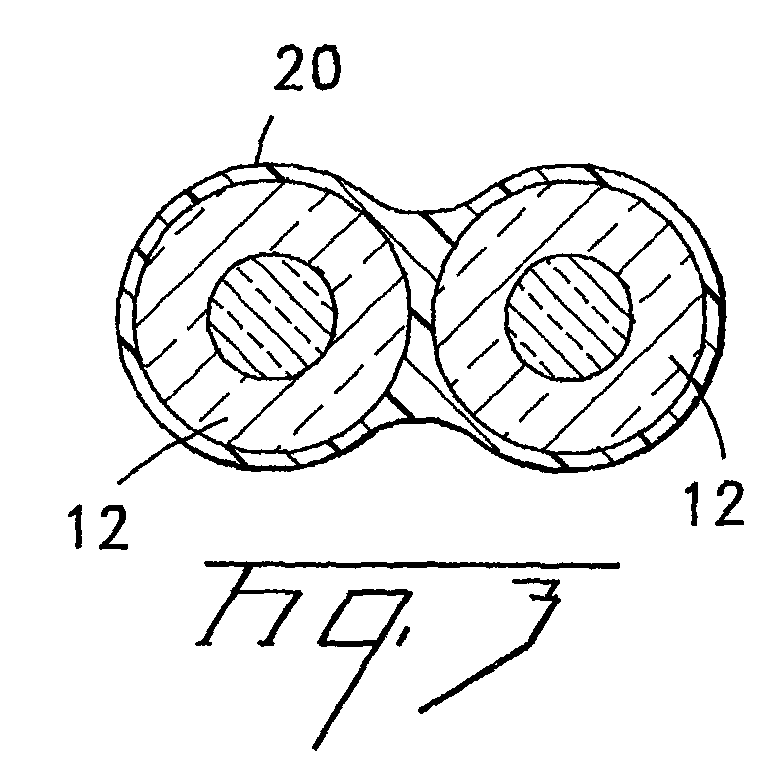
- fibers 12 are arranged closely adjacent and parallel to each other, and a coating 20 of a fluid composition is applied to the fibers such that the fibers are coated on all sides and the fluid composition fills the space between the fibers as shown in cross-section in FIG. 3.
- the fluid composition is one that is initially fluid when applied but will solidify under appropriate conditions to form a solid material suitable for binding fibers 12 together.
- compositions can be used, including but not limited to solvent-based compositions (including polymer-based and other types) that solidify upon evaporation of the solvent from the composition, polymer-based compositions that are curable to become solid by heating the composition, and polymer-based compositions that are curable to become solid by exposing the composition to radiant energy such as UV radiation.
- solvent-based compositions including polymer-based and other types
- polymer-based compositions that are curable to become solid by heating the composition and polymer-based compositions that are curable to become solid by exposing the composition to radiant energy such as UV radiation.
- One way in which coating 20 can be applied is by providing a bath (not shown) of the fluid composition and passing fibers 12 through the bath.
- coating 20 is preferred to remove coating 20 from the surfaces of fibers 12 except for the opposing surfaces of the adjacent fibers between which the fluid composition extends to fill the space between the fibers. Removal of coating 20 from all but the opposing surfaces is preferred because it is desirable that fibers 12 be substantially free of any coating when they are separated from each other, so that the fibers can be inserted into a connector without first having to be stripped of a coating.
- removal of the coating from surfaces of the fibers is accomplished by passing the fibers through an aperture 22 of a tool 24, shown in plan view in FIG. 4.
- Aperture 22 is configured as a pair of holes, each of which is slightly larger in diameter than a fiber 12, connected by a narrowed waist portion 28.
- the aperture in tool 24 in each case is formed as a plurality of holes (corresponding to the number of fibers), adjacent ones of which are connected by a narrowed waist portion as shown in FIG. 4.
- the material of web 14 can be deposited on the fibers by means of one or more orifices and/or syringes.
- FIG. 5 is a plan view of tool 24, seen from a downstream side of the tool with regard to the direction in which fibers 12 are moving through aperture 22. Fibers 12 emerge from aperture 22 substantially free of the coating but with a web 14 of the fluid composition connected between the fibers.
- the method in accordance with the present embodiment of the invention essentially comprises applying a hardenable composition in fluid form over the fibers and then removing the composition from surfaces of the fibers except for the opposing surfaces of the fibers between which it is desired to form a connecting web.
- the remaining fluid composition between the fibers is caused or allowed to cure to solidify it.
- the fibers are passed adjacent to a device 30 for causing the composition to cure. Curing can be done by elliptical mirrors with D type bulbs.
- Device 30 may be a heater, such as a forced-air or radiant heater, in the case of a heat-curable composition. A heater may also be used for hastening the evaporation of a solvent from a solvent-based composition.
- device 30 is an emitter of the desired type of radiation, such as a UV light.
- the composition solidifies to form web 14 joining fibers 12 together.
- One such method is to bind the fibers together using a coating of a coloring compound that is applied to the fibers for imparting a desired color to the fibers. It is commonplace to apply such coloring compounds to fibers for identification purposes so that fibers of one color can be visually distinguished from other differently colored fibers within a cable.
- the coloring compound is applied to each of the fibers and, while the compound is still fluid or tacky, the fibers are pressed together, causing the fluid or tacky coatings on the fibers to meld together so that the fibers resemble the condition shown in FIG. 3. The fibers are held together until the compound solidifies. As a result, the fibers are bound together.
- each fiber is provided with a coating of a solid material that is soluble in a volatile solvent.
- the coating may be a solvent-based ink that is applied to each fiber for imparting a desired color to each fiber.
- An example of such an ink is a solvent-based polyvinyl chloride (PVC) ink.
- PVC polyvinyl chloride
- the ink is initially applied to a fiber it is fluid, but solidifies by evaporation of its solvent base to form the ink coating.
- the ink is partially dissolved or softened by applying a quantity of the solvent to the coating to render the ink tacky.
- the tacky ink of one fiber is brought into contact with the tacky ink on another fiber and the fibers are held together until the solvent evaporates so that the ink again becomes solid.
- the resolidified portions of the ink coatings in contact with each other thus become bonded together.
- This method can be practiced, for example, by moving the fibers to be joined along closely adjacent generally parallel paths along which a solvent applicator is disposed between the fibers, bringing the fibers into contact with the applicator such that the fibers run over the applicator and solvent is applied to the fibers to render the coatings tacky, and then bringing the fibers into contact with each other downstream of the applicator.
- a heater and/or blower can be provided to hasten the evaporation of the solvent from the fibers.
- the solid soluble coating need not be an ink for coloring the fibers, but could be a coating provided solely for binding the fibers together. Where fibers are to be colored, however, it is advantageous for the ink coating to serve both the coloring and binding purposes.
- the web is strong enough to prevent sliding of one fiber relative to the other, but is weak enough to allow the fibers to be pulled apart with relatively little force such that the optical fibers are not broken.
- the fibers are substantially free of any binding material that would have to be removed prior to cleaving or other preparatory steps before inserting the fibers into a connector.
- the optical fiber assembly of the invention is different from a conventional optical fiber ribbon in which the fibers are totally enveloped in a matrix of material having a relatively high modulus and hardness, such that the matrix material must be peeled off the fibers before the fibers can be separated from one another.
- the invention thus enables time to be saved when preparing fibers for insertion into a connector, since stripping of matrix material is unnecessary.
- the invention also enables the fibers to be held in fixed longitudinal positions relative to one another after end portions of the fibers have been separated from one another. Because the fiber ends thus do not slide relative to each other, the fibers can be cleaved to the same length and the fibers are inhibited from thereafter shifting their longitudinal positions relative to one another yet transverse motion is allowed.
- the invention thereby facilitates the assembly of connectors having stub fibers onto the ends of the fibers.
- Yet another feature of the invention is that, unlike optical ribbons that do not permit bending in the plane of the ribbon, fibers joined in accordance with the invention can bend in the plane of the fiber assembly over a localized lengthwise part of the assembly by allowing the bonds between the fibers to break in the bent part so that the fibers are free to twist and move in various directions relative to one another. This feature can enhance optical performance of the fiber assembly.
- the intermittent web allows the fibers to flex in opposite transverse directions. This makes the fiber assembly bound with the intermittent web more flexible than conventional optical ribbons. Because the fiber bundles are manufactured with tension applied to the optical fibers at the time the web material is solidified and the tension is removed once the fibers are cabled, a residual differential strain may be imparted to the fibers if the tensions during manufacture are not exactly equal.
- the intermittent web allows the differential strains to be relaxed in the region between the webs preventing degraded optical performance of the fibers due to the residual strain. Conventional optical ribbons are difficult to separate and leave residue on the fibers after separation which can negatively affect connectorization.
Landscapes
- Physics & Mathematics (AREA)
- General Physics & Mathematics (AREA)
- Optics & Photonics (AREA)
- Optical Fibers, Optical Fiber Cores, And Optical Fiber Bundles (AREA)
- Surface Treatment Of Glass Fibres Or Filaments (AREA)
Abstract
Description
Claims (14)
- An optical fiber assembly, comprising:a plurality of optical fibers arranged generally parallel to one another such that each optical fiber is closely adjacent to at least one other optical fiber, each of said optical fibers comprising a silica based core and an outer coating layer;a web of material, distinct from said outer coating layers, being disposed between said optical fibers and bound to said outer coating layers, the web lightly tacking the adjacent fibers together to prevent relative sliding between the fibers along a longitudinal direction thereof and being readily broken when pulling forces are exerted on the fibers away from each other transverse to the longitudinal direction such that the fibers can be separated without the fibers being broken by the pulling forces.
- The interconnect cable of claim 1, said web being longitudinally continuous.
- The interconnect cable of claim 1, said web being intermittent.
- The interconnect cable of claim 1, said optical fibers being surrounded by a tube having an OD of about 800 to 2,000 µm.
- The interconnect cable of claim 1, an outer layer of at least one of said optical fibers being a coloring layer with an OD of about 255 µm.
- The interconnect cable of claim 1, said web having a height of about 100 to 125 µm.
- The interconnect cable of claim 1, said web having a width of about 50 µm or less.
- The interconnect cable of claim 1, said web subtends an angle α of about 120° with respect to a center of one of said fibers.
- The interconnect cable of claim 1, said web comprises a small filament coated or impregnated with a resin material, said filament comprising a fiber or tension element.
- The interconnect cable of claim 1, a fiber-to-fiber spacing being about 245 ±10 µm to about 300 µm ±10 µm.
- The interconnect cable of claim 1, the outer layers of the fibers being upcoated to an OD of about 300 to 1000 µm or more, more preferably about 650 to 800 µm, therefore the fiber-to-fiber spacing may be up to about 1,000 µm or more.
- The interconnect cable of claim 1, the adhesion strength of said web being a minimum of about 2 grams/inch.
- The interconnect cable of claim 1, said web being formed of a materials having a glass transition temperature of about -30 to +70C.
- The interconnect cable of claim 1, said web having a modulus range of about 25 to 400 MPa.
Applications Claiming Priority (2)
| Application Number | Priority Date | Filing Date | Title |
|---|---|---|---|
| US749001 | 2000-12-27 | ||
| US09/749,001 US6584257B1 (en) | 2000-12-27 | 2000-12-27 | Fiber optic assembly and method of making same |
Publications (2)
| Publication Number | Publication Date |
|---|---|
| EP1235087A2 true EP1235087A2 (en) | 2002-08-28 |
| EP1235087A3 EP1235087A3 (en) | 2004-02-04 |
Family
ID=25011814
Family Applications (1)
| Application Number | Title | Priority Date | Filing Date |
|---|---|---|---|
| EP01126647A Withdrawn EP1235087A3 (en) | 2000-12-27 | 2001-11-08 | Fiber optic cable assembly and method of making same |
Country Status (2)
| Country | Link |
|---|---|
| US (1) | US6584257B1 (en) |
| EP (1) | EP1235087A3 (en) |
Cited By (2)
| Publication number | Priority date | Publication date | Assignee | Title |
|---|---|---|---|---|
| WO2006090002A1 (en) * | 2005-02-23 | 2006-08-31 | Corelase Oy | New fiber optic devices |
| WO2020006368A1 (en) * | 2018-06-29 | 2020-01-02 | Ipg Photonics Corporation | Active waveguide for high-power laser |
Families Citing this family (47)
| Publication number | Priority date | Publication date | Assignee | Title |
|---|---|---|---|---|
| US7715675B2 (en) | 2003-07-18 | 2010-05-11 | Corning Incorporated | Optical fiber coating system and coated optical fiber |
| US7050688B2 (en) | 2003-07-18 | 2006-05-23 | Corning Cable Systems Llc | Fiber optic articles, assemblies, and cables having optical waveguides |
| US20050056952A1 (en) * | 2003-09-15 | 2005-03-17 | Walker James K. | Method of manufacturing multi-polymer optical fiber cable |
| US7193155B2 (en) * | 2003-10-29 | 2007-03-20 | Superior Essex Communications Lp | Communication cables including colored conductors or fibers and methods for making and using the same |
| US7269318B2 (en) * | 2004-03-23 | 2007-09-11 | Superior Essex Communications, Lp | In-color fiber optic cable identification method |
| US7567739B2 (en) * | 2007-01-31 | 2009-07-28 | Draka Comteq B.V. | Fiber optic cable having a water-swellable element |
| CN102057309B (en) * | 2008-06-30 | 2014-04-16 | 日本电信电话株式会社 | Fiber optic cables and ribbons |
| US20110110636A1 (en) * | 2009-11-12 | 2011-05-12 | Nave Samuel D | Fiber Optic Cables Having Limited Strength Elements |
| US8682123B2 (en) | 2010-07-15 | 2014-03-25 | Draka Comteq, B.V. | Adhesively coupled optical fibers and enclosing tape |
| JP5564026B2 (en) * | 2011-10-18 | 2014-07-30 | 株式会社フジクラ | Optical fiber tape core and optical fiber cable storing the optical fiber core |
| JP5391296B2 (en) | 2012-03-02 | 2014-01-15 | 株式会社フジクラ | Optical fiber tape core and optical fiber cable storing the optical fiber core |
| CA3178019A1 (en) | 2012-05-02 | 2013-11-07 | Afl Telecommunications Llc | Round and small diameter optical cables with a ribbon-like optical fiber structure |
| US9389382B2 (en) | 2014-06-03 | 2016-07-12 | Corning Optical Communications LLC | Fiber optic ribbon cable and ribbon |
| JP6412779B2 (en) * | 2014-11-20 | 2018-10-24 | 株式会社フジクラ | Optical fiber ribbon, optical fiber cable, and optical fiber ribbon manufacturing method |
| EP3329311A4 (en) | 2015-07-31 | 2019-03-27 | Corning Optical Communications LLC | FIBER OPTIC ROLLER TAPE |
| US9835812B2 (en) * | 2015-08-04 | 2017-12-05 | Corning Incorporated | Multi-optical fiber aggregate |
| JP5947967B2 (en) * | 2015-08-28 | 2016-07-06 | 株式会社フジクラ | Optical fiber ribbon and optical fiber cable |
| JP6569429B2 (en) * | 2015-09-25 | 2019-09-04 | 住友電気工業株式会社 | Optical fiber ribbon |
| JP6657976B2 (en) * | 2016-01-13 | 2020-03-04 | 住友電気工業株式会社 | Intermittent connection type optical fiber ribbon and optical cable |
| US10989888B2 (en) * | 2016-02-02 | 2021-04-27 | Ofs Fitel, Llc | Flexible ribbon structure and method for making |
| US9880368B2 (en) * | 2016-02-02 | 2018-01-30 | Ofs Fitel, Llc | Method for high speed processing of partially bonded ribbon structures |
| JP2017156558A (en) * | 2016-03-02 | 2017-09-07 | 古河電気工業株式会社 | Manufacturing method for optical fiber cable, and manufacturing method for optical fiber tape ribbon |
| JP6117394B1 (en) * | 2016-03-07 | 2017-04-19 | 株式会社フジクラ | Manufacturing method and manufacturing apparatus for optical fiber ribbon |
| JP6620627B2 (en) * | 2016-03-23 | 2019-12-18 | 住友電気工業株式会社 | Manufacturing method and manufacturing apparatus for optical fiber ribbon |
| EP3258219A1 (en) * | 2016-06-15 | 2017-12-20 | Eidgenössische Materialprüfungs- und Forschungsanstalt EMPA | In-situ and real time quality control in additive manufacturing process |
| EP3491441B1 (en) * | 2016-07-27 | 2020-05-27 | Prysmian S.p.A. | Flexible optical-fiber ribbon |
| CA3045290A1 (en) * | 2016-11-29 | 2018-06-07 | Corning Optical Communications LLC | Laser sintered flexible ribbon |
| EP3561564B1 (en) * | 2016-12-20 | 2025-07-16 | Furukawa Electric Co., Ltd. | Method for manufacturing optical fiber intermittent tape core and optical fiber intermittent tape core |
| JP2018106098A (en) * | 2016-12-28 | 2018-07-05 | 株式会社フジクラ | Method of manufacturing intermittently fixed optical fiber ribbon |
| JP2018151590A (en) * | 2017-03-15 | 2018-09-27 | 株式会社巴川製紙所 | Optical fiber wiring member |
| AU2017423261B2 (en) | 2017-07-11 | 2023-07-20 | Prysmian S.P.A. | An optical fiber ribbon and a method of producing the same |
| PL3652576T3 (en) | 2017-07-11 | 2022-11-07 | Prysmian S.P.A. | An optical fiber ribbon assembly and a method of producing the same |
| EP3665521B1 (en) * | 2017-08-08 | 2023-11-08 | Corning Research & Development Corporation | Rollable optical fiber ribbon with low attenuation, large mode field diameter optical fiber and cable |
| JP6453970B1 (en) * | 2017-10-05 | 2019-01-16 | 株式会社フジクラ | Intermittently connected optical fiber tape and method for manufacturing intermittently connected optical fiber tape |
| US11256051B2 (en) | 2018-01-15 | 2022-02-22 | Prysmian S.P.A. | Flexible optical-fiber ribbon |
| US11500171B2 (en) | 2018-01-15 | 2022-11-15 | Prysmian S.P.A. | Optical fiber ribbon and a method and system of producing the same |
| AU2018401778C1 (en) | 2018-01-15 | 2024-08-08 | Prysmian S.P.A. | A method for producing a flexible optical fiber ribbon and said ribbon. |
| US11262516B2 (en) | 2018-07-05 | 2022-03-01 | Prysmian S.P.A. | High density optical cables |
| JP2018180553A (en) * | 2018-07-12 | 2018-11-15 | 株式会社フジクラ | Manufacturing method of intermittent fixing tape core wire |
| EP3869251A4 (en) * | 2018-10-19 | 2022-06-15 | Furukawa Electric Co., Ltd. | Optical fiber cable |
| US11150424B2 (en) * | 2018-12-06 | 2021-10-19 | Sterlite Technologies Limited | Rollable optical fiber ribbon |
| JPWO2020189772A1 (en) * | 2019-03-20 | 2020-09-24 | ||
| US10884213B1 (en) | 2019-11-14 | 2021-01-05 | Prysmian S.P.A. | Optical-fiber ribbon with distorted sinusoidal adhesive pattern and method therefor |
| US11442238B2 (en) | 2020-12-22 | 2022-09-13 | Prysmian S.P.A. | Optical-fiber ribbon with spaced optical-fiber units |
| US11860429B2 (en) | 2020-12-22 | 2024-01-02 | Prysmian S.P.A. | Optical-fiber ribbon with spaced optical-fiber units |
| US11460652B2 (en) | 2020-12-22 | 2022-10-04 | Prysmian S.P.A. | Optical-fiber ribbon with adhesive-free gaps |
| US20230168441A1 (en) * | 2021-11-30 | 2023-06-01 | Corning Research & Development Corporation | Unjacketed fiber optic cable assembly, and cable assembly including connector with travel limited ferrule |
Family Cites Families (17)
| Publication number | Priority date | Publication date | Assignee | Title |
|---|---|---|---|---|
| GB1570624A (en) * | 1975-12-11 | 1980-07-02 | Western Electric Co | Optical fibre transmission arrangements |
| DE2724536A1 (en) * | 1977-05-31 | 1978-12-14 | Siemens Ag | RIBBON OR FLAT CABLES WITH OPTICAL TRANSMISSION ELEMENTS |
| NL8403629A (en) * | 1984-05-23 | 1985-12-16 | Philips Nv | OPTICAL TAPE CABLE, METHOD FOR MANUFACTURING IT AND AN OPTICAL CABLE COMPOSED OF SEVERAL TAPE CABLES. |
| GB8531673D0 (en) * | 1985-12-23 | 1986-02-05 | Telephone Cables Ltd | Optical fibre units |
| DE3606626A1 (en) | 1986-02-28 | 1987-09-03 | Siemens Ag | Flat conductor cable having a plurality of optical fibres, and method for producing it |
| DE3606617A1 (en) | 1986-02-28 | 1987-09-03 | Siemens Ag | FLAT TAPE LINE WITH SEVERAL LIGHTWAVE CORE AND METHOD FOR THE PRODUCTION THEREOF |
| JP2573633B2 (en) | 1987-11-26 | 1997-01-22 | 住友電気工業株式会社 | Tape-type optical fiber manufacturing equipment |
| US4900126A (en) | 1988-06-30 | 1990-02-13 | American Telephone & Telegraph Co. | Bonded array of transmission media |
| JPH0256510A (en) | 1988-08-23 | 1990-02-26 | Sumitomo Electric Ind Ltd | Production of tape type coated optical fibers |
| US4952020A (en) * | 1989-08-09 | 1990-08-28 | Amp Incorporated | Ribbon cable with optical fibers and electrical conductors |
| TW198118B (en) | 1991-09-27 | 1993-01-11 | Minnesota Mining & Mfg | |
| FR2693560A1 (en) * | 1992-07-10 | 1994-01-14 | Alcatel Cable | Cylindrical fibre=optic cable with fibres arranged around central core - binds fibres together in flexible resin which is then rolled up into cylindrical cable form incorporating cord to rip open resin to re-form ribbon |
| US5442722A (en) * | 1994-07-25 | 1995-08-15 | Siecor Corporation | Optical fiber ribbon with zip cord |
| JP3773584B2 (en) * | 1996-03-04 | 2006-05-10 | トヨクニ電線株式会社 | Fiber optic tape cable |
| JP3825506B2 (en) * | 1996-09-02 | 2006-09-27 | Jsr株式会社 | Liquid curable resin composition |
| US5966489A (en) | 1997-06-30 | 1999-10-12 | Siecor Corporation | Fiber optic ribbon interconnect cable |
| US6134360A (en) | 1998-07-07 | 2000-10-17 | Jds Uniphase Inc. | Optical fibre sleeve |
-
2000
- 2000-12-27 US US09/749,001 patent/US6584257B1/en not_active Expired - Lifetime
-
2001
- 2001-11-08 EP EP01126647A patent/EP1235087A3/en not_active Withdrawn
Cited By (2)
| Publication number | Priority date | Publication date | Assignee | Title |
|---|---|---|---|---|
| WO2006090002A1 (en) * | 2005-02-23 | 2006-08-31 | Corelase Oy | New fiber optic devices |
| WO2020006368A1 (en) * | 2018-06-29 | 2020-01-02 | Ipg Photonics Corporation | Active waveguide for high-power laser |
Also Published As
| Publication number | Publication date |
|---|---|
| EP1235087A3 (en) | 2004-02-04 |
| US20030118301A1 (en) | 2003-06-26 |
| US6584257B1 (en) | 2003-06-24 |
Similar Documents
| Publication | Publication Date | Title |
|---|---|---|
| US6584257B1 (en) | Fiber optic assembly and method of making same | |
| US11169342B2 (en) | Flexible optical-fiber ribbon | |
| US11209594B2 (en) | Cable with overcoated non-coplanar groups of fusion spliced optical fibers, and fabrication method | |
| TWI666471B (en) | Optical fiber ribbon core and optical fiber cable | |
| US12001070B2 (en) | Flexible optical-fiber ribbon | |
| CZ258994A3 (en) | Connector for optical fibers | |
| KR20150054936A (en) | Remote grip multi-fiber connector | |
| JPH05307116A (en) | Optical fiber clamp | |
| CN100399090C (en) | Fiber optic ribbon with preferential pull section | |
| US11754786B2 (en) | Multi-fiber splice protector and cable assembly with intra-connector splices, and fabrication method | |
| US11808983B2 (en) | Multi-fiber splice protector with compact splice-on furcation housing | |
| WO1998016856A1 (en) | Method of production of optical connector | |
| EP1312955B1 (en) | Process for coupling optical fibres | |
| JP5150201B2 (en) | Adhesive connection member and optical connection structure using the same | |
| JP3710532B2 (en) | Optical connector assembly method | |
| JP2005309367A (en) | Optical fiber connector, optical fiber connector, and optical fiber connection method | |
| US20250314835A1 (en) | Laminate pitch conversion | |
| GB2175410A (en) | Optical fibre fusion splicing | |
| TW363137B (en) | Enhanced ribbon strippability using coating additives | |
| US20040079734A1 (en) | Low back reflection fiber optic cable termination and method of making same | |
| WO2002039164A2 (en) | High temperature fiber optic splint | |
| US11867947B2 (en) | Cable assembly having routable splice protectors | |
| GB2261078A (en) | Optical fibre connector having capillary tubes | |
| JPH02189506A (en) | Formation of fiber ribbon of single coated fiber | |
| JP3392991B2 (en) | Recoating method of fusion spliced part of optical fiber |
Legal Events
| Date | Code | Title | Description |
|---|---|---|---|
| PUAI | Public reference made under article 153(3) epc to a published international application that has entered the european phase |
Free format text: ORIGINAL CODE: 0009012 |
|
| AK | Designated contracting states |
Kind code of ref document: A2 Designated state(s): AT BE CH CY DE DK ES FI FR GB GR IE IT LI LU MC NL PT SE TR |
|
| AX | Request for extension of the european patent |
Free format text: AL;LT;LV;MK;RO;SI |
|
| PUAL | Search report despatched |
Free format text: ORIGINAL CODE: 0009013 |
|
| AK | Designated contracting states |
Kind code of ref document: A3 Designated state(s): AT BE CH CY DE DK ES FI FR GB GR IE IT LI LU MC NL PT SE TR |
|
| AX | Request for extension of the european patent |
Extension state: AL LT LV MK RO SI |
|
| STAA | Information on the status of an ep patent application or granted ep patent |
Free format text: STATUS: THE APPLICATION IS DEEMED TO BE WITHDRAWN |
|
| AKX | Designation fees paid | ||
| REG | Reference to a national code |
Ref country code: DE Ref legal event code: 8566 |
|
| 18D | Application deemed to be withdrawn |
Effective date: 20040602 |