EP1234964A1 - Method and apparatus for controlling the flow rate of a gas passing a throttle element - Google Patents
Method and apparatus for controlling the flow rate of a gas passing a throttle element Download PDFInfo
- Publication number
- EP1234964A1 EP1234964A1 EP01400449A EP01400449A EP1234964A1 EP 1234964 A1 EP1234964 A1 EP 1234964A1 EP 01400449 A EP01400449 A EP 01400449A EP 01400449 A EP01400449 A EP 01400449A EP 1234964 A1 EP1234964 A1 EP 1234964A1
- Authority
- EP
- European Patent Office
- Prior art keywords
- flow
- transfer function
- pumped
- throttle
- throttle valve
- Prior art date
- Legal status (The legal status is an assumption and is not a legal conclusion. Google has not performed a legal analysis and makes no representation as to the accuracy of the status listed.)
- Withdrawn
Links
- 238000000034 method Methods 0.000 title claims abstract description 13
- 238000002485 combustion reaction Methods 0.000 claims description 13
- 230000001276 controlling effect Effects 0.000 claims description 12
- 238000001914 filtration Methods 0.000 claims description 8
- 238000011144 upstream manufacturing Methods 0.000 claims description 3
- 230000001105 regulatory effect Effects 0.000 claims description 2
- 238000010586 diagram Methods 0.000 description 6
- 210000000056 organ Anatomy 0.000 description 5
- 235000001954 papillon Nutrition 0.000 description 5
- 244000229285 papillon Species 0.000 description 5
- 238000005070 sampling Methods 0.000 description 4
- 230000003416 augmentation Effects 0.000 description 2
- 238000002347 injection Methods 0.000 description 2
- 239000007924 injection Substances 0.000 description 2
- 241001415961 Gaviidae Species 0.000 description 1
- 238000004378 air conditioning Methods 0.000 description 1
- 230000003321 amplification Effects 0.000 description 1
- 235000021183 entrée Nutrition 0.000 description 1
- 238000003199 nucleic acid amplification method Methods 0.000 description 1
- 230000000750 progressive effect Effects 0.000 description 1
Images

Classifications
-
- F—MECHANICAL ENGINEERING; LIGHTING; HEATING; WEAPONS; BLASTING
- F02—COMBUSTION ENGINES; HOT-GAS OR COMBUSTION-PRODUCT ENGINE PLANTS
- F02D—CONTROLLING COMBUSTION ENGINES
- F02D41/00—Electrical control of supply of combustible mixture or its constituents
- F02D41/02—Circuit arrangements for generating control signals
- F02D41/04—Introducing corrections for particular operating conditions
- F02D41/08—Introducing corrections for particular operating conditions for idling
- F02D41/083—Introducing corrections for particular operating conditions for idling taking into account engine load variation, e.g. air-conditionning
-
- F—MECHANICAL ENGINEERING; LIGHTING; HEATING; WEAPONS; BLASTING
- F02—COMBUSTION ENGINES; HOT-GAS OR COMBUSTION-PRODUCT ENGINE PLANTS
- F02D—CONTROLLING COMBUSTION ENGINES
- F02D11/00—Arrangements for, or adaptations to, non-automatic engine control initiation means, e.g. operator initiated
- F02D11/06—Arrangements for, or adaptations to, non-automatic engine control initiation means, e.g. operator initiated characterised by non-mechanical control linkages, e.g. fluid control linkages or by control linkages with power drive or assistance
- F02D11/10—Arrangements for, or adaptations to, non-automatic engine control initiation means, e.g. operator initiated characterised by non-mechanical control linkages, e.g. fluid control linkages or by control linkages with power drive or assistance of the electric type
- F02D11/105—Arrangements for, or adaptations to, non-automatic engine control initiation means, e.g. operator initiated characterised by non-mechanical control linkages, e.g. fluid control linkages or by control linkages with power drive or assistance of the electric type characterised by the function converting demand to actuation, e.g. a map indicating relations between an accelerator pedal position and throttle valve opening or target engine torque
-
- F—MECHANICAL ENGINEERING; LIGHTING; HEATING; WEAPONS; BLASTING
- F02—COMBUSTION ENGINES; HOT-GAS OR COMBUSTION-PRODUCT ENGINE PLANTS
- F02D—CONTROLLING COMBUSTION ENGINES
- F02D41/00—Electrical control of supply of combustible mixture or its constituents
- F02D41/0002—Controlling intake air
- F02D2041/0017—Controlling intake air by simultaneous control of throttle and exhaust gas recirculation
-
- F—MECHANICAL ENGINEERING; LIGHTING; HEATING; WEAPONS; BLASTING
- F02—COMBUSTION ENGINES; HOT-GAS OR COMBUSTION-PRODUCT ENGINE PLANTS
- F02D—CONTROLLING COMBUSTION ENGINES
- F02D41/00—Electrical control of supply of combustible mixture or its constituents
- F02D41/0025—Controlling engines characterised by use of non-liquid fuels, pluralities of fuels, or non-fuel substances added to the combustible mixtures
- F02D41/0047—Controlling exhaust gas recirculation [EGR]
- F02D41/0065—Specific aspects of external EGR control
Definitions
- the present invention relates to methods and devices for controlling a gas flow (generally air) passing through a throttle device the position is adjusted by an actuator, from a flow rate setpoint pumped from cyclically by a receiver, a collecting volume being interposed between the throttling organ and the receiving organ.
- a gas flow generally air
- the invention finds a particularly important application in internal combustion engine control systems having at least one combustion chamber of variable volume during a cycle, supplied with air at constant or variable pressure through a throttle whose position is controlled by an actuator, then through a manifold intake.
- the throttling organ is generally constituted by a butterfly rotary and the latter term will be used later. However, it should be attributed a general meaning and as applying to any throttling organ having a adjustable position.
- the present invention aims in particular to provide a method and a device air flow control better than those previously known to requirements of the practice, in particular in that they significantly reduce the pilot time constant.
- the invention notably proposes a method for controlling the air flow through a butterfly controlled by an actuator from a mass flow set point cyclically pumped through the throttle valve and a Downstream intake manifold according to claim 1.
- This process is based on the fact that one can, without undue error, model the transfer function of a collector of the kind used in internal combustion engines as a first order function having as an inlet the mass flow of air passing through the butterfly and as an outlet the mass flow of pumped air, with a time constant which is a function itself pumped mass flow and cycle frequency (i.e. engine speed).
- the time constant ⁇ can be determined by a calibration prior and stored in a table with several entries.
- the position given to the butterfly (opening angle in general) can be deduced at any time from Q butterfly by reading in a table taking into account temperature and pressure, supplied by sensors.
- the invention also proposes a control device implementing the above method according to claim 6, as well as a system for internal combustion engine control in which the flow rate setpoint pumped is determined by a calculation unit from a torque setpoint supplied by a body controlled by the driver and possibly by additional torque calls due to the start-up of auxiliaries such as a air conditioning unit or a robotic gearbox in the case of a vehicle.
- auxiliaries such as a air conditioning unit or a robotic gearbox in the case of a vehicle.
- the invention proposes a device for controlling a throttle body controlled by an actuator and regulating a flow rate and a air pressure cyclically drawn through a function buffer volume known transfer device according to claim 5.
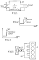
- FIG. 1 indicates the transfer function of a buffer volume 23 placed downstream of a throttle member 8.
- this transfer function if it is linear, can be written in Laplace notation: 1 / (1 + ⁇ p)
- This transfer function causes, in the event of rapid opening of the throttle resulting in a flow step at the throttle level, by a progressive increase in the pumped flow (FIG. 2). On the contrary, it is possible to obtain a flow step pumped very quickly, as indicated in dashes in FIG. 3, by an excessive increase in the butterfly flow (curve in solid lines).
- the butterfly must be ordered by implementing a transfer function compensating for that of the buffer volume, of the form: 1 + ⁇ .p K / (1 + ⁇ f.p)
- the diagram in FIG. 4 shows the operations and the loops of regulation involved in controlling the opening angle of the throttle valve 8 of an internal combustion engine 9, in response to a request from torque produced by the driver's action on an accelerator pedal and by variations in the torque required by auxiliaries using power to the engine.
- Most of the blocks shown in Figure 1 can be constituted by wired circuits or by programs which in this case can be executed either by a specific microprocessor or by the engine control computer provided on current vehicles.
- the calculations are performed in digital form, which involves sampling and store the input data. On current engines, a period 0.01 s sampling rate was found to be satisfactory.
- Block 10 of Figure 4 represents the calculation of a digital signal indicating the average torque indicated CMI, which must be supplied by engine 9 and corresponds to an average air flow determined in steady state.
- the data of input of block 10 are the position of the pedal, supplied on an input 12 and representative of the setpoint torque that the driver wishes to apply to wheels, the engine speed N applied to an input 13 and giving the frequency debit calls by the rooms, and finally an entry indicating the call of torque possibly required by auxiliaries.
- the sensors are analog, digital to analog converters not shown are provided.
- the output signal from block 10, representative of the average torque indicated CMI is translated by a block 14 into a flow rate setpoint Qpomtig, which will called Qpc.
- a regulation loop includes a subtractor 16 which receives the setpoint signal Qpc on an input and a signal indicating the pumped flow estimated real Qpr on the other entry.
- the error ⁇ is applied, as well as Qpc, to a filter 18, generally of the PID type.
- the output of this filter constitutes a signal flow objective pumped Qpo. But assimilate Qpo to a flow instruction butterfly neglects the transfer function due to the dynamic behavior of air in the collector.
- Block 19 estimates the actual pumped flow mainly from temperature data T, pressure P and speed N of rotation of the engine.
- the signal representative of Qpo is not used directly to calculate a value of setpoint ⁇ c of the throttle opening angle in a circuit 20 taking into counts the characteristic curve of the butterfly and the temperature T and the pressure F gas upstream of the throttle valve.
- the signal Qpo is processed by a block 22 which applies a function inverse to the estimated transfer function of the collector 23 (figure 2), as will be seen below so as to provide an outlet a Qpapo signal representative of a throttle flow objective.
- the butterfly 8 is controlled, in a conventional manner, by a loop of regulation comprising a subtractor 24 which receives on an input the opening of setpoint ⁇ c and on the other input a signal representative of the actual opening current ⁇ r and blocks 26 for controlling the actuator 28 of the throttle valve and 27 for supply of a signal ⁇ r representative of the opening angle.
- the correction introduced consists in applying, to the signal representative of Qpomdozens, a reverse transfer function.
- This operation amounts to a high pass filtering of type 1 + ⁇ .tp / K, where ⁇ and K are coefficients which depend on fixed characteristics of the engine (volume of the manifold, number of combustion chambers, ...) and of the motor speed.
- This filtering also results in amplification of noise.
- it is desirable to add filtering low pass having a time constant ⁇ f much shorter than the time constant of the collector (at least an order of magnitude).
- the process can be modified to take into account an exhaust gas recirculation.
- the flow admitted to the combustion chambers that is to say the pumped flow, depends on both the butterfly flow and the recirculation flow.
Landscapes
- Engineering & Computer Science (AREA)
- Chemical & Material Sciences (AREA)
- Combustion & Propulsion (AREA)
- Mechanical Engineering (AREA)
- General Engineering & Computer Science (AREA)
- Electrical Control Of Air Or Fuel Supplied To Internal-Combustion Engine (AREA)
- Combined Controls Of Internal Combustion Engines (AREA)
Abstract
Description
La présente invention concerne les procédés et dispositifs de pilotage d'un débit de gaz (généralement d'air) traversant un organe d'étranglement dont la position est réglée par un actionneur, à partir d'une consigne de débit pompé de façon cyclique par un récepteur, un volume collecteur étant interposé entre l'organe d'étranglement et l'organe récepteur.The present invention relates to methods and devices for controlling a gas flow (generally air) passing through a throttle device the position is adjusted by an actuator, from a flow rate setpoint pumped from cyclically by a receiver, a collecting volume being interposed between the throttling organ and the receiving organ.
L'invention trouve une application particulièrement importante dans les systèmes de commande de moteurs à combustion interne ayant au moins une chambre de combustion de volume variable au cours d'un cycle, alimentée en air à une pression constante ou variable à travers un organe d'étranglement dont la position est commandée par un actionneur, puis à travers un collecteur d'admission. L'organe d'étranglement est généralement constitué par un papillon rotatif et ce dernier terme sera utilisé par la suite. On devra cependant y attribuer un sens général et comme s'appliquant à tout organe d'étranglement ayant une position ajustable.The invention finds a particularly important application in internal combustion engine control systems having at least one combustion chamber of variable volume during a cycle, supplied with air at constant or variable pressure through a throttle whose position is controlled by an actuator, then through a manifold intake. The throttling organ is generally constituted by a butterfly rotary and the latter term will be used later. However, it should be attributed a general meaning and as applying to any throttling organ having a adjustable position.
On connaít déjà des dispositifs de pilotage d'un débit massique d'air traversant un papillon à partir d'une consigne de débit pompé en aval du papillon, comportant un circuit d'asservissement qui commande la position du papillon en fonction de la consigne de débit et de paramètres de fonctionnement tels que la température de l'air et la pression. Dans le cas d'un moteur, le débit moyen d'air pompé par les chambres de combustion à travers le collecteur est égal, en régime permanent, au débit d'air qui traverse l'organe d'étranglement et la connaissance de la consigne de débit massique pompé (découlant elle-même d'une consigne de couple fixée par le conducteur et de la valeur de paramètres de fonctionnement du moteur) permet au circuit de commande de déterminer la position à donner à l'organe d'étranglement, le débit à travers le papillon étant égal au débit de consigne. Mais lors des transitoires, le collecteur introduit sur le débit au niveau du papillon un filtrage passe bas dont il n'a pas été tenu compte jusqu'ici. Les dispositifs existants ont en conséquence l'inconvénient d'une constante de temps importante, d'autant plus longue que le volume de l'espace compris entre le papillon et l'emplacement de consigne de débit (entrée de l'organe récepteur) est important.We already know devices for controlling a mass air flow crossing a throttle valve from a flow rate instruction pumped downstream of the throttle valve, comprising a servo circuit which controls the position of the throttle in function of the flow setpoint and operating parameters such as air temperature and pressure. In the case of an engine, the average air flow pumped by the combustion chambers through the manifold is equal, in steady state, at the air flow which passes through the throttle member and the knowledge of the mass flow setpoint pumped (itself arising a torque setpoint set by the driver and the parameter value engine) allows the control circuit to determine the position to be given to the throttle member, the flow rate through the butterfly being equal to the set flow. But during transients, the collector introduced on the flow rate at the throttle valve low pass filtering which has not been taken into account so far. Existing devices therefore have the disadvantage of a large time constant, the longer the volume of space between the throttle valve and the flow setpoint location (entry of the receiving organ) is important.
La présente invention vise notamment à fournir un procédé et un dispositif de pilotage de débit d'air répondant mieux que ceux antérieurement connus aux exigences de la pratique, notamment en ce qu'ils réduisent notablement la constante de temps du pilotage.The present invention aims in particular to provide a method and a device air flow control better than those previously known to requirements of the practice, in particular in that they significantly reduce the pilot time constant.
Dans ce but, l'invention propose notamment un procédé de pilotage du
débit d'air traversant un papillon commandé par un actionneur à partir d'une
consigne de débit massique pompé de façon cyclique à travers le papillon et un
collecteur d'admission placé en aval, conforme à la revendication 1.To this end, the invention notably proposes a method for controlling the
air flow through a butterfly controlled by an actuator from a
mass flow set point cyclically pumped through the throttle valve and a
Downstream intake manifold according to
Ce procédé est fondé sur le fait que l'on peut, sans erreur excessive, modéliser la fonction de transfert d'un collecteur du genre utilisé dans les moteurs à combustion interne sous forme d'une fonction du premier ordre ayant comme entrée le débit massique d'air traversant le papillon et comme sortie le débit massique d'air pompé, avec une constante de temps qui est fonction elle-même du débit massique pompé et de la fréquence de cycle (c'est-à-dire du régime dans le cas d'un moteur).This process is based on the fact that one can, without undue error, model the transfer function of a collector of the kind used in internal combustion engines as a first order function having as an inlet the mass flow of air passing through the butterfly and as an outlet the mass flow of pumped air, with a time constant which is a function itself pumped mass flow and cycle frequency (i.e. engine speed).
Cette fonction de transfert peut donc s'écrire de la façon suivante :
La constante de temps τ peut être déterminée par un étalonnage préalable et mémorisée dans une table à plusieurs entrées. The time constant τ can be determined by a calibration prior and stored in a table with several entries.
La position donnée au papillon (angle d'ouverture en général) peut être déduite à tout instant de Q papillon par lecture dans une table tenant compte de la température et de la pression, fournies par des capteurs.The position given to the butterfly (opening angle in general) can be deduced at any time from Q butterfly by reading in a table taking into account temperature and pressure, supplied by sensors.
Sur certains moteurs à combustion interne, il est prévu une recirculation de gaz d'échappement, qui s'ajoute alors au débit massique traversant le papillon pour constituer le débit pompé. Il peut être tenu compte de cet ajout en modifiant de façon simple le mode de commande.On certain internal combustion engines, recirculation of exhaust gas, which then adds to the mass flow through the throttle valve to constitute the pumped flow. This addition can be taken into account by modifying simply the command mode.
L'invention propose également un dispositif de pilotage mettant en oeuvre le procédé ci-dessus, conforme à la revendication 6, ainsi qu'un système de commande de moteur à combustion interne dans lequel la consigne de débit pompé est déterminée par un organe de calcul à partir d'une consigne de couple fournie par un organe commandé par le conducteur et éventuellement par des appels de couple supplémentaires dûs à la mise en route d'auxiliaires tels qu'un appareil de climatisation ou une boíte de vitesse robotisée dans le cas d'un véhicule.The invention also proposes a control device implementing the above method according to claim 6, as well as a system for internal combustion engine control in which the flow rate setpoint pumped is determined by a calculation unit from a torque setpoint supplied by a body controlled by the driver and possibly by additional torque calls due to the start-up of auxiliaries such as a air conditioning unit or a robotic gearbox in the case of a vehicle.
La mise en oeuvre de l'invention se traduit, lors de d'application d'un échelon de consigne de couple, par la venue du papillon dans une position dépassant celle qu'il prendra une fois le nouveau régime permanent établi. Ce dépassement ou "overshoot", dont l'amplitude dépend du régime moteur initial, ne se traduit pas pour autant par un dépassement de la pression dans le collecteur et n'a aucun inconvénient.The implementation of the invention results, when applying a torque setpoint step, by the coming of the butterfly in a position beyond what it will take once the new permanent regime is established. This overshoot or "overshoot", the amplitude of which depends on the initial engine speed, does not mean that the pressure in the collector and has no drawbacks.
Plus généralement, l'invention propose un dispositif de pilotage d'un organe d'étranglement commandé par un actionneur et réglant un débit et une pression d'air aspiré de façon cyclique à travers un volume tampon de fonction de transfert connue, conforme à la revendication 5.More generally, the invention proposes a device for controlling a throttle body controlled by an actuator and regulating a flow rate and a air pressure cyclically drawn through a function buffer volume known transfer device according to claim 5.
En dehors de la commande d'un papillon, ce dispositif est notamment applicable :
- à un circuit de recirculation des gaz d'échappement (éventuellement en même temps qu'à la commande de papillon),
- à un circuit de suralimentation par compresseur ou turbo-compresseur.
- an exhaust gas recirculation circuit (possibly at the same time as the throttle valve control),
- to a supercharging circuit by compressor or turbo-compressor.
Il n'est pas nécessaire que la fonction de transfert sont du premier ordre. It is not necessary that the transfer function are first order.
Les caractéristiques ci-dessus ainsi que d'autres apparaítront mieux à la lecture de la description qui suit d'un mode particulier de réalisation donné à titre d'exemple non limitatif. La description se réfère aux dessins qui l'accompagnent, dans lesquels :
- la figure 1 est un schéma destiné à faire apparaítre le principe du pilotage d'un organe d'étranglement placé en amont d'un volume tampon ;
- la figure 2 est un diagramme montrant l'évolution du débit pompé lors d'une augmentation brutale du débit papillon ;
- la figure 3, similaire à la figure 2, montre la variation à faire subir au débit papillon pour obtenir une augmentation rapide d'un échelon du débit pompé ;
- la figure 4 est un synoptique représentant, sous forme de blocs successifs, les opérations qui interviennent dans le pilotage du débit massique d'air traversant un papillon ;
- la figure 5 est un schéma montrant les éléments essentiels du circuit pneumatique d'alimentation des chambres de combustion d'un moteur à injection.
- Figure 1 is a diagram for showing the principle of piloting a throttling member placed upstream of a buffer volume;
- Figure 2 is a diagram showing the evolution of the flow pumped during a sudden increase in the butterfly flow;
- Figure 3, similar to Figure 2, shows the variation to be subjected to the butterfly flow to obtain a rapid increase of one step of the pumped flow;
- Figure 4 is a block diagram representing, in the form of successive blocks, the operations involved in controlling the mass flow of air passing through a butterfly;
- FIG. 5 is a diagram showing the essential elements of the pneumatic circuit supplying the combustion chambers of an injection engine.
Le schéma de la figure 1 indique la fonction de transfert d'un volume
tampon 23 placé en aval d'un organe d'étranglement 8. Comme on le verra plus
en détail plus loin, cette fonction de transfert, si elle est linéaire, peut être écrite
dans la notation de Laplace:
Cette fonction de transfert provoque, en cas d'ouverture rapide du papillon
se traduisant par un échelon de débit au niveau du papillon, par une
augmentation progressive du débit pompé (figure 2). On peut au contraire obtenir
un échelon de débit pompé très rapidement, comme indiqué en tirets sur la
figure 3, par une augmentation excessive du débit papillon (courbe en traits
pleins). Pour cela, le papillon doit être commandé en mettant en oeuvre une
fonction de transfert compensant celle du volume tampon, de la forme :
Le synoptique de la figure 4 montre les opérations et les boucles de
régulation qui interviennent dans la commande de l'angle d'ouverture du
papillon 8 d'un moteur à combustion interne 9, en réponse à une demande de
couple matérialisée par l'action du conducteur sur une pédale d'accélérateur et
par les variations du couple requis par des auxiliaires empruntant de la puissance
au moteur. La plupart des blocs représentés sur la figure 1 peuvent être
constitués par des circuits câblés ou par des programmes qui dans ce cas
pourront être exécutés soit par un microprocesseur particulier, soit par le
calculateur de contrôle moteur prévu sur les véhicules actuels. Les calculs sont
effectués sous forme numérique, ce qui implique d'échantillonner et de
mémoriser les données d'entrée. Sur les moteurs actuels, une période
d'échantillonnage de l'ordre de 0,01 s s'est révélée satisfaisante.The diagram in FIG. 4 shows the operations and the loops of
regulation involved in controlling the opening angle of the
Le bloc 10 de la figure 4 représente le calcul d'un signal numérique
indiquant le couple moyen indiqué CMI, que devra fournir le moteur 9 et
correspond à un débit moyen d'air déterminé en régime permanent. Les données
d'entrée du bloc 10 sont la position de la pédale, fournie sur une entrée 12 et
représentative du couple de consigne que le conducteur souhaite appliquer aux
roues, le régime N du moteur appliqué sur une entrée 13 et donnant la fréquence
des appels de débit par les chambres, et enfin une entrée indiquant l'appel de
couple requis éventuellement par des auxiliaires. Lorsque les capteurs sont
analogiques, des convertisseurs numérique-analogique non représentés sont
prévus. Le signal de sortie du bloc 10, représentatif du couple moyen indiqué
CMI, est traduit par un bloc 14 en une consigne de débit Qpompé, qui sera
dénommée Qpc. Une boucle de régulation comporte un soustracteur 16 qui reçoit
le signal de consigne Qpc sur une entrée et un signal indiquant le débit pompé
réel estimé Qpr sur l'autre entrée. L'erreur ε est appliquée, ainsi que Qpc, à un
filtre 18, généralement de type PID. La sortie de ce filtre constitue un signal
d'objectif de débit pompé Qpo. Mais assimiler Qpo à une consigne de débit
papillon néglige la fonction de transfert due au comportement dynamique de l'air
dans le collecteur. Le bloc 19 estime le débit pompé réel à partir principalement
des données de température T, de pression P et de vitesse N de rotation du
moteur.
Dans un système de commande de moteur suivant l'invention, le signal
représentatif de Qpo n'est pas utilisé directement pour calculer une valeur de
consigne αc de l'angle d'ouverture du papillon dans un circuit 20 prenant en
compte la courbe caractéristique du papillon et la température T et la pression
Pdes gaz en amont du papillon. Le signal Qpo est traité par un bloc 22 qui lui
applique une fonction inverse de la fonction de transfert estimée du collecteur
d'admission 23 (figure 2), comme on le verra plus loin de façon à fournir en sortie
un signal Qpapo représentatif d'un objectif de débit papillon.In a motor control system according to the invention, the signal
representative of Qpo is not used directly to calculate a value of
setpoint αc of the throttle opening angle in a
Le papillon 8 est commandé, de façon classique, par une boucle de
régulation comprenant un soustracteur 24 qui reçoit sur une entrée l'ouverture de
consigne αc et sur l'autre entrée un signal représentatif de l'ouverture réelle
courante αr et des blocs 26 de commande de l'actionneur 28 du papillon et 27 de
fourniture d'un signal αr représentatif de l'angle d'ouverture.The
La correction introduite par le bloc 22 est déterminée à partir d'un modèle
de comportement du collecteur 23 de la forme donnée en (1). Elle peut s'écrire,
en transformée de Laplace :
La correction introduite consiste à appliquer, au signal représentatif de
Qpompé, une fonction de transfert inverse. Cette opération revient à un filtrage
passe haut du type 1 + τ.tp/K, où τ et K sont des coefficients qui dépendent de
caractéristiques fixes du moteur (volume du collecteur, nombre de chambres de
combustion,...) et de la vitesse du moteur. Ce filtrage entraíne également une
amplification des bruits. Pour l'éviter et pour couper les constantes de temps les
plus faibles du modèle, qui seraient incompatibles avec la période
d'échantillonnage qui est choisie à une valeur suffisamment faible pour tenir
compte du théorème de Shannon, il est souhaitable d'ajouter un filtrage passe
bas, ayant une constante de temps τf beaucoup plus courte que la constante de
temps du collecteur (d'au moins un ordre de grandeur). On a alors :
Ce sera la valeur de la constante de temps la plus courte qui fixera alors une durée maximale pour la période d'échantillonnage.It will be the value of the shortest time constant which will then set a maximum duration for the sampling period.
L'application du filtrage passe haut inverse de la fonction de transfert du
collecteur implique de disposer des valeurs de τ et de K dans les diverses
conditions de fonctionnement du moteur. Il suffira généralement de mémoriser
une table de valeurs de τ en fonction de la vitesse de rotation du moteur et de la
température de l'air dans le collecteur. En effet, τ pourra généralement s'écrire
sous la forme :
Le procédé dont les étapes ont été décrites plus haut est encore
applicable lorsque le couple demandé par le conducteur et matérialisé par le
signal sur l'entrée 12 doit être juxtaposé à une consigne de couple
supplémentaire demandée par un auxiliaire, par exemple par une boíte de
vitesse automatique ou robotisée, par un régulateur de vitesse ou de distance, le
système du freinage ou un limiteur de performances moteur. Dans ce cas, pour
rendre moins brutale l'action provoquée par un échelon de couple, la consigne de
débit pompé provenant de la boíte est traduite en débit papillon par un filtre à
avance de phase inversant aussi la dynamique du collecteur.The process whose steps have been described above is still
applicable when the torque requested by the driver and materialized by the
signal on
Enfin, le procédé peut être modifié pour prendre en compte une
recirculation de gaz d'échappement. Dans ce cas, le débit admis aux chambres
de combustion, c'est-à-dire le débit pompé, dépend à la fois du débit papillon et
du débit de recirculation. Dans ce cas, l'hypothèse selon laquelle est fondée la
régulation ci-dessus, qui est que la masse d'air dans le collecteur M est reliée
aux débits par :
Dans ce cas, l'équation unique reliant Qpap à Qpompé est remplacée par un système de deux équations dont l'une fait intervenir la constante de temps du système de recirculation, ce qui conduit simplement à appliquer deux filtrages passe haut différents, correspondant à des constantes de temps distinctes, aux signaux représentatifs du débit papillon et du débit de recirculation.In this case, the unique equation connecting Qpap to Qpompé is replaced by a system of two equations, one of which involves the time constant of recirculation system, which simply means applying two filters different high pass, corresponding to different time constants, signals representative of the butterfly flow and the recirculation flow.
Claims (7)
Priority Applications (1)
| Application Number | Priority Date | Filing Date | Title |
|---|---|---|---|
| EP01400449A EP1234964A1 (en) | 2001-02-20 | 2001-02-20 | Method and apparatus for controlling the flow rate of a gas passing a throttle element |
Applications Claiming Priority (1)
| Application Number | Priority Date | Filing Date | Title |
|---|---|---|---|
| EP01400449A EP1234964A1 (en) | 2001-02-20 | 2001-02-20 | Method and apparatus for controlling the flow rate of a gas passing a throttle element |
Publications (1)
| Publication Number | Publication Date |
|---|---|
| EP1234964A1 true EP1234964A1 (en) | 2002-08-28 |
Family
ID=8182629
Family Applications (1)
| Application Number | Title | Priority Date | Filing Date |
|---|---|---|---|
| EP01400449A Withdrawn EP1234964A1 (en) | 2001-02-20 | 2001-02-20 | Method and apparatus for controlling the flow rate of a gas passing a throttle element |
Country Status (1)
| Country | Link |
|---|---|
| EP (1) | EP1234964A1 (en) |
Cited By (4)
| Publication number | Priority date | Publication date | Assignee | Title |
|---|---|---|---|---|
| EP1408385A1 (en) * | 2002-10-11 | 2004-04-14 | STMicroelectronics S.A. | Method for controlling a dynamic system, using a fuzzy logic model of at least one inverse transfer function of the system |
| FR2910549A1 (en) * | 2006-12-21 | 2008-06-27 | Renault Sas | Injector drift correcting method for e.g. diesel engine of vehicle, involves determining drift correction value of injector to be added to nominal set point value by utilizing indicated average torque estimation for cylinders |
| FR2910550A1 (en) * | 2006-12-21 | 2008-06-27 | Renault Sas | Injector drift correction method for e.g. motor vehicle's direct injection oil engine, involves comparing actual injected and set point fuel quantities, and determining correction to be carried out to set point by using torque estimation |
| EP2351924B1 (en) * | 2008-10-31 | 2016-12-28 | Toyota Jidosha Kabushiki Kaisha | Internal combustion engine controller |
Citations (6)
| Publication number | Priority date | Publication date | Assignee | Title |
|---|---|---|---|---|
| DE4215107C1 (en) * | 1992-05-07 | 1994-01-20 | Daimler Benz Ag | Control system for fuel-injected IC engine - calculates required fuel quantity from accelerator pedal position, in turn used to calculate air intake mass flow rate |
| DE19515855A1 (en) * | 1995-04-29 | 1996-10-31 | Volkswagen Ag | Method for adjusting the movement of a performance-changing control element |
| DE19618385A1 (en) * | 1996-05-08 | 1997-11-13 | Bosch Gmbh Robert | Automobile engine management method |
| EP0899439A2 (en) * | 1997-08-28 | 1999-03-03 | Nissan Motor Company, Limited | Control apparatus and method for internal combustion engine |
| US5925089A (en) * | 1996-07-10 | 1999-07-20 | Yamaha Hatsudoki Kabushiki Kaisha | Model-based control method and apparatus using inverse model |
| EP0987417A2 (en) * | 1998-09-18 | 2000-03-22 | Hitachi, Ltd. | Method and apparatus for controlling intake airflow rate of an engine and method for controlling output |
-
2001
- 2001-02-20 EP EP01400449A patent/EP1234964A1/en not_active Withdrawn
Patent Citations (6)
| Publication number | Priority date | Publication date | Assignee | Title |
|---|---|---|---|---|
| DE4215107C1 (en) * | 1992-05-07 | 1994-01-20 | Daimler Benz Ag | Control system for fuel-injected IC engine - calculates required fuel quantity from accelerator pedal position, in turn used to calculate air intake mass flow rate |
| DE19515855A1 (en) * | 1995-04-29 | 1996-10-31 | Volkswagen Ag | Method for adjusting the movement of a performance-changing control element |
| DE19618385A1 (en) * | 1996-05-08 | 1997-11-13 | Bosch Gmbh Robert | Automobile engine management method |
| US5925089A (en) * | 1996-07-10 | 1999-07-20 | Yamaha Hatsudoki Kabushiki Kaisha | Model-based control method and apparatus using inverse model |
| EP0899439A2 (en) * | 1997-08-28 | 1999-03-03 | Nissan Motor Company, Limited | Control apparatus and method for internal combustion engine |
| EP0987417A2 (en) * | 1998-09-18 | 2000-03-22 | Hitachi, Ltd. | Method and apparatus for controlling intake airflow rate of an engine and method for controlling output |
Cited By (6)
| Publication number | Priority date | Publication date | Assignee | Title |
|---|---|---|---|---|
| EP1408385A1 (en) * | 2002-10-11 | 2004-04-14 | STMicroelectronics S.A. | Method for controlling a dynamic system, using a fuzzy logic model of at least one inverse transfer function of the system |
| FR2845780A1 (en) * | 2002-10-11 | 2004-04-16 | St Microelectronics Sa | METHOD FOR CONTROLLING A DYNAMIC SYSTEM, USING A FOULD LOGIC MODEL OF AT LEAST ONE REVERSE TRANSFER FUNCTION OF THIS SYSTEM |
| US7013187B2 (en) | 2002-10-11 | 2006-03-14 | Stmicroelectronics, S.A. | Control procedure using a fuzzy logic model of at least one inverse transfer function of a dynamic system |
| FR2910549A1 (en) * | 2006-12-21 | 2008-06-27 | Renault Sas | Injector drift correcting method for e.g. diesel engine of vehicle, involves determining drift correction value of injector to be added to nominal set point value by utilizing indicated average torque estimation for cylinders |
| FR2910550A1 (en) * | 2006-12-21 | 2008-06-27 | Renault Sas | Injector drift correction method for e.g. motor vehicle's direct injection oil engine, involves comparing actual injected and set point fuel quantities, and determining correction to be carried out to set point by using torque estimation |
| EP2351924B1 (en) * | 2008-10-31 | 2016-12-28 | Toyota Jidosha Kabushiki Kaisha | Internal combustion engine controller |
Similar Documents
| Publication | Publication Date | Title |
|---|---|---|
| FR2863066A1 (en) | METHOD FOR CONTROLLING AT LEAST ONE ORGAN FOR ADJUSTING A MASS FLOW DRIVE | |
| FR2759116A1 (en) | METHOD FOR CONTROLLING AN INTERNAL COMBUSTION ENGINE | |
| FR2822898A1 (en) | METHOD AND DEVICE FOR CONTROLLING AND / OR DIAGNOSING A CONTROL SYSTEM INFLUENCING A MASS FLOW | |
| FR2736010A1 (en) | METHOD AND DEVICE FOR CONTROLLING THE DRIVE UNIT OF A MOTOR VEHICLE | |
| FR2879526A1 (en) | METHOD FOR AIDING STARTING A MOTOR VEHICLE AND ASSOCIATED DEVICE | |
| EP1234964A1 (en) | Method and apparatus for controlling the flow rate of a gas passing a throttle element | |
| FR2749040A1 (en) | PROCEDURE FOR ADJUSTING THE PRESSURE IN THE SUCTION DUCT OF AN INTERNAL COMBUSTION ENGINE AND DEVICE FOR IMPLEMENTING THE PROCESS | |
| FR2783616A1 (en) | Control method for current input to electro hydraulic valve using variable modulation process involving signal superimposition | |
| FR2840362A1 (en) | METHOD FOR CONTROLLING THE FILLING OF AN INTERNAL COMBUSTION ENGINE | |
| FR2804472A1 (en) | Method of controlling airflow through motor vehicle internal combustion engine intake involves determining position of butterfly valve as a function of flow across valve and external parameters | |
| CA2443251C (en) | Process and device for automatically controlling the thrust of at least one engine of an aircraft in level flight at stable speed | |
| FR2861860A1 (en) | Vehicle driving unit management method, involves predefining set point value for magnitude of output of driving unit, and releasing thrust of unit when set point value of magnitude passes below characteristic thrust value | |
| EP1792106B1 (en) | Method for multi-operating mode control of an automated transmission for a motor vehicle, in particular for idle speed running with inactivated brake and corresponding device | |
| WO2005119033A2 (en) | Method for controlling a set torque to be applied to wheels of an automatic transmission for a motor vehicle and corresponding device | |
| FR2768460A1 (en) | METHOD FOR IMPLEMENTING AN INTERNAL COMBUSTION ENGINE | |
| FR2750734A1 (en) | METHOD AND DEVICE FOR CONTROLLING THE INJECTED QUANTITY OF FUEL FITTED TO THE CYLINDERS OF AN INTERNAL COMBUSTION ENGINE | |
| FR2868473A1 (en) | METHOD AND DEVICE FOR MANAGING AN INTERNAL COMBUSTION ENGINE | |
| WO1996009464A1 (en) | Device for driving the accessories of a motor vehicle combustion engine | |
| FR2774425A1 (en) | METHOD AND DEVICE FOR CONTROLLING AN INTERNAL COMBUSTION ENGINE | |
| FR2851298A1 (en) | Thermal engine control process, involves defining mass charging that should be applied to combustion chamber, from bunch of curve characteristics, desired torque, and size explaining desired air/fuel ratio | |
| FR2990656A1 (en) | Device for real-time development of torque set point on e.g. front wheel axle, of car, has selection module developing torque set point by selecting smaller value between torque reference and magnitude linked to another torque reference | |
| FR2837432A1 (en) | Motor vehicle gearchange control method involves controlling clutch actuator dependent on vehicle acceleration and drive slip | |
| FR2890118A1 (en) | METHOD AND DEVICE FOR MANAGING AN INTERNAL COMBUSTION ENGINE | |
| EP1574694B1 (en) | Apparatus and method controlling metering of injected fuel in a diesel engine | |
| EP0170574B1 (en) | Method and apparatus for controlling the intake air flow in a thermal engine during idling |
Legal Events
| Date | Code | Title | Description |
|---|---|---|---|
| PUAI | Public reference made under article 153(3) epc to a published international application that has entered the european phase |
Free format text: ORIGINAL CODE: 0009012 |
|
| 17P | Request for examination filed |
Effective date: 20011013 |
|
| AK | Designated contracting states |
Kind code of ref document: A1 Designated state(s): AT BE CH CY DE DK ES FI FR GB GR IE IT LI LU MC NL PT SE TR |
|
| AX | Request for extension of the european patent |
Free format text: AL;LT;LV;MK;RO;SI |
|
| RAP1 | Party data changed (applicant data changed or rights of an application transferred) |
Owner name: JOHNSON CONTROLS AUTOMOTIVE ELECTRONICS |
|
| AKX | Designation fees paid |
Designated state(s): DE ES FR GB IT NL |
|
| 17Q | First examination report despatched |
Effective date: 20040809 |
|
| STAA | Information on the status of an ep patent application or granted ep patent |
Free format text: STATUS: THE APPLICATION IS DEEMED TO BE WITHDRAWN |
|
| 18D | Application deemed to be withdrawn |
Effective date: 20050222 |