EP1234964A1 - Verfahren und Vorrichtung zur Steuerung des Gasflusses an einem Drosselelement - Google Patents
Verfahren und Vorrichtung zur Steuerung des Gasflusses an einem Drosselelement Download PDFInfo
- Publication number
- EP1234964A1 EP1234964A1 EP01400449A EP01400449A EP1234964A1 EP 1234964 A1 EP1234964 A1 EP 1234964A1 EP 01400449 A EP01400449 A EP 01400449A EP 01400449 A EP01400449 A EP 01400449A EP 1234964 A1 EP1234964 A1 EP 1234964A1
- Authority
- EP
- European Patent Office
- Prior art keywords
- flow
- transfer function
- pumped
- throttle
- throttle valve
- Prior art date
- Legal status (The legal status is an assumption and is not a legal conclusion. Google has not performed a legal analysis and makes no representation as to the accuracy of the status listed.)
- Withdrawn
Links
- 238000000034 method Methods 0.000 title claims abstract description 13
- 238000002485 combustion reaction Methods 0.000 claims description 13
- 230000001276 controlling effect Effects 0.000 claims description 12
- 238000001914 filtration Methods 0.000 claims description 8
- 238000011144 upstream manufacturing Methods 0.000 claims description 3
- 230000001105 regulatory effect Effects 0.000 claims description 2
- 238000010586 diagram Methods 0.000 description 6
- 210000000056 organ Anatomy 0.000 description 5
- 235000001954 papillon Nutrition 0.000 description 5
- 244000229285 papillon Species 0.000 description 5
- 238000005070 sampling Methods 0.000 description 4
- 230000003416 augmentation Effects 0.000 description 2
- 238000002347 injection Methods 0.000 description 2
- 239000007924 injection Substances 0.000 description 2
- 241001415961 Gaviidae Species 0.000 description 1
- 238000004378 air conditioning Methods 0.000 description 1
- 230000003321 amplification Effects 0.000 description 1
- 235000021183 entrée Nutrition 0.000 description 1
- 238000003199 nucleic acid amplification method Methods 0.000 description 1
- 230000000750 progressive effect Effects 0.000 description 1
Images

Classifications
-
- F—MECHANICAL ENGINEERING; LIGHTING; HEATING; WEAPONS; BLASTING
- F02—COMBUSTION ENGINES; HOT-GAS OR COMBUSTION-PRODUCT ENGINE PLANTS
- F02D—CONTROLLING COMBUSTION ENGINES
- F02D41/00—Electrical control of supply of combustible mixture or its constituents
- F02D41/02—Circuit arrangements for generating control signals
- F02D41/04—Introducing corrections for particular operating conditions
- F02D41/08—Introducing corrections for particular operating conditions for idling
- F02D41/083—Introducing corrections for particular operating conditions for idling taking into account engine load variation, e.g. air-conditionning
-
- F—MECHANICAL ENGINEERING; LIGHTING; HEATING; WEAPONS; BLASTING
- F02—COMBUSTION ENGINES; HOT-GAS OR COMBUSTION-PRODUCT ENGINE PLANTS
- F02D—CONTROLLING COMBUSTION ENGINES
- F02D11/00—Arrangements for, or adaptations to, non-automatic engine control initiation means, e.g. operator initiated
- F02D11/06—Arrangements for, or adaptations to, non-automatic engine control initiation means, e.g. operator initiated characterised by non-mechanical control linkages, e.g. fluid control linkages or by control linkages with power drive or assistance
- F02D11/10—Arrangements for, or adaptations to, non-automatic engine control initiation means, e.g. operator initiated characterised by non-mechanical control linkages, e.g. fluid control linkages or by control linkages with power drive or assistance of the electric type
- F02D11/105—Arrangements for, or adaptations to, non-automatic engine control initiation means, e.g. operator initiated characterised by non-mechanical control linkages, e.g. fluid control linkages or by control linkages with power drive or assistance of the electric type characterised by the function converting demand to actuation, e.g. a map indicating relations between an accelerator pedal position and throttle valve opening or target engine torque
-
- F—MECHANICAL ENGINEERING; LIGHTING; HEATING; WEAPONS; BLASTING
- F02—COMBUSTION ENGINES; HOT-GAS OR COMBUSTION-PRODUCT ENGINE PLANTS
- F02D—CONTROLLING COMBUSTION ENGINES
- F02D41/00—Electrical control of supply of combustible mixture or its constituents
- F02D41/0002—Controlling intake air
- F02D2041/0017—Controlling intake air by simultaneous control of throttle and exhaust gas recirculation
-
- F—MECHANICAL ENGINEERING; LIGHTING; HEATING; WEAPONS; BLASTING
- F02—COMBUSTION ENGINES; HOT-GAS OR COMBUSTION-PRODUCT ENGINE PLANTS
- F02D—CONTROLLING COMBUSTION ENGINES
- F02D41/00—Electrical control of supply of combustible mixture or its constituents
- F02D41/0025—Controlling engines characterised by use of non-liquid fuels, pluralities of fuels, or non-fuel substances added to the combustible mixtures
- F02D41/0047—Controlling exhaust gas recirculation [EGR]
- F02D41/0065—Specific aspects of external EGR control
Definitions
- the present invention relates to methods and devices for controlling a gas flow (generally air) passing through a throttle device the position is adjusted by an actuator, from a flow rate setpoint pumped from cyclically by a receiver, a collecting volume being interposed between the throttling organ and the receiving organ.
- a gas flow generally air
- the invention finds a particularly important application in internal combustion engine control systems having at least one combustion chamber of variable volume during a cycle, supplied with air at constant or variable pressure through a throttle whose position is controlled by an actuator, then through a manifold intake.
- the throttling organ is generally constituted by a butterfly rotary and the latter term will be used later. However, it should be attributed a general meaning and as applying to any throttling organ having a adjustable position.
- the present invention aims in particular to provide a method and a device air flow control better than those previously known to requirements of the practice, in particular in that they significantly reduce the pilot time constant.
- the invention notably proposes a method for controlling the air flow through a butterfly controlled by an actuator from a mass flow set point cyclically pumped through the throttle valve and a Downstream intake manifold according to claim 1.
- This process is based on the fact that one can, without undue error, model the transfer function of a collector of the kind used in internal combustion engines as a first order function having as an inlet the mass flow of air passing through the butterfly and as an outlet the mass flow of pumped air, with a time constant which is a function itself pumped mass flow and cycle frequency (i.e. engine speed).
- the time constant ⁇ can be determined by a calibration prior and stored in a table with several entries.
- the position given to the butterfly (opening angle in general) can be deduced at any time from Q butterfly by reading in a table taking into account temperature and pressure, supplied by sensors.
- the invention also proposes a control device implementing the above method according to claim 6, as well as a system for internal combustion engine control in which the flow rate setpoint pumped is determined by a calculation unit from a torque setpoint supplied by a body controlled by the driver and possibly by additional torque calls due to the start-up of auxiliaries such as a air conditioning unit or a robotic gearbox in the case of a vehicle.
- auxiliaries such as a air conditioning unit or a robotic gearbox in the case of a vehicle.
- the invention proposes a device for controlling a throttle body controlled by an actuator and regulating a flow rate and a air pressure cyclically drawn through a function buffer volume known transfer device according to claim 5.
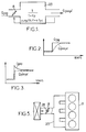
- FIG. 1 indicates the transfer function of a buffer volume 23 placed downstream of a throttle member 8.
- this transfer function if it is linear, can be written in Laplace notation: 1 / (1 + ⁇ p)
- This transfer function causes, in the event of rapid opening of the throttle resulting in a flow step at the throttle level, by a progressive increase in the pumped flow (FIG. 2). On the contrary, it is possible to obtain a flow step pumped very quickly, as indicated in dashes in FIG. 3, by an excessive increase in the butterfly flow (curve in solid lines).
- the butterfly must be ordered by implementing a transfer function compensating for that of the buffer volume, of the form: 1 + ⁇ .p K / (1 + ⁇ f.p)
- the diagram in FIG. 4 shows the operations and the loops of regulation involved in controlling the opening angle of the throttle valve 8 of an internal combustion engine 9, in response to a request from torque produced by the driver's action on an accelerator pedal and by variations in the torque required by auxiliaries using power to the engine.
- Most of the blocks shown in Figure 1 can be constituted by wired circuits or by programs which in this case can be executed either by a specific microprocessor or by the engine control computer provided on current vehicles.
- the calculations are performed in digital form, which involves sampling and store the input data. On current engines, a period 0.01 s sampling rate was found to be satisfactory.
- Block 10 of Figure 4 represents the calculation of a digital signal indicating the average torque indicated CMI, which must be supplied by engine 9 and corresponds to an average air flow determined in steady state.
- the data of input of block 10 are the position of the pedal, supplied on an input 12 and representative of the setpoint torque that the driver wishes to apply to wheels, the engine speed N applied to an input 13 and giving the frequency debit calls by the rooms, and finally an entry indicating the call of torque possibly required by auxiliaries.
- the sensors are analog, digital to analog converters not shown are provided.
- the output signal from block 10, representative of the average torque indicated CMI is translated by a block 14 into a flow rate setpoint Qpomtig, which will called Qpc.
- a regulation loop includes a subtractor 16 which receives the setpoint signal Qpc on an input and a signal indicating the pumped flow estimated real Qpr on the other entry.
- the error ⁇ is applied, as well as Qpc, to a filter 18, generally of the PID type.
- the output of this filter constitutes a signal flow objective pumped Qpo. But assimilate Qpo to a flow instruction butterfly neglects the transfer function due to the dynamic behavior of air in the collector.
- Block 19 estimates the actual pumped flow mainly from temperature data T, pressure P and speed N of rotation of the engine.
- the signal representative of Qpo is not used directly to calculate a value of setpoint ⁇ c of the throttle opening angle in a circuit 20 taking into counts the characteristic curve of the butterfly and the temperature T and the pressure F gas upstream of the throttle valve.
- the signal Qpo is processed by a block 22 which applies a function inverse to the estimated transfer function of the collector 23 (figure 2), as will be seen below so as to provide an outlet a Qpapo signal representative of a throttle flow objective.
- the butterfly 8 is controlled, in a conventional manner, by a loop of regulation comprising a subtractor 24 which receives on an input the opening of setpoint ⁇ c and on the other input a signal representative of the actual opening current ⁇ r and blocks 26 for controlling the actuator 28 of the throttle valve and 27 for supply of a signal ⁇ r representative of the opening angle.
- the correction introduced consists in applying, to the signal representative of Qpomdozens, a reverse transfer function.
- This operation amounts to a high pass filtering of type 1 + ⁇ .tp / K, where ⁇ and K are coefficients which depend on fixed characteristics of the engine (volume of the manifold, number of combustion chambers, ...) and of the motor speed.
- This filtering also results in amplification of noise.
- it is desirable to add filtering low pass having a time constant ⁇ f much shorter than the time constant of the collector (at least an order of magnitude).
- the process can be modified to take into account an exhaust gas recirculation.
- the flow admitted to the combustion chambers that is to say the pumped flow, depends on both the butterfly flow and the recirculation flow.
Landscapes
- Engineering & Computer Science (AREA)
- Chemical & Material Sciences (AREA)
- Combustion & Propulsion (AREA)
- Mechanical Engineering (AREA)
- General Engineering & Computer Science (AREA)
- Electrical Control Of Air Or Fuel Supplied To Internal-Combustion Engine (AREA)
- Combined Controls Of Internal Combustion Engines (AREA)
Priority Applications (1)
| Application Number | Priority Date | Filing Date | Title |
|---|---|---|---|
| EP01400449A EP1234964A1 (de) | 2001-02-20 | 2001-02-20 | Verfahren und Vorrichtung zur Steuerung des Gasflusses an einem Drosselelement |
Applications Claiming Priority (1)
| Application Number | Priority Date | Filing Date | Title |
|---|---|---|---|
| EP01400449A EP1234964A1 (de) | 2001-02-20 | 2001-02-20 | Verfahren und Vorrichtung zur Steuerung des Gasflusses an einem Drosselelement |
Publications (1)
| Publication Number | Publication Date |
|---|---|
| EP1234964A1 true EP1234964A1 (de) | 2002-08-28 |
Family
ID=8182629
Family Applications (1)
| Application Number | Title | Priority Date | Filing Date |
|---|---|---|---|
| EP01400449A Withdrawn EP1234964A1 (de) | 2001-02-20 | 2001-02-20 | Verfahren und Vorrichtung zur Steuerung des Gasflusses an einem Drosselelement |
Country Status (1)
| Country | Link |
|---|---|
| EP (1) | EP1234964A1 (de) |
Cited By (4)
| Publication number | Priority date | Publication date | Assignee | Title |
|---|---|---|---|---|
| EP1408385A1 (de) * | 2002-10-11 | 2004-04-14 | STMicroelectronics S.A. | Verfahren zur Steuerung eines dynamischen Systems mit Hilfe eines Fuzzy-Logic-Modells wenigstens einer inversen Übertragungsfunktion des Systems |
| FR2910550A1 (fr) * | 2006-12-21 | 2008-06-27 | Renault Sas | Procede de correction des derives d'un injecteur du moteur. |
| FR2910549A1 (fr) * | 2006-12-21 | 2008-06-27 | Renault Sas | Procede de correction des derives des injecteurs d'un moteur |
| EP2351924B1 (de) * | 2008-10-31 | 2016-12-28 | Toyota Jidosha Kabushiki Kaisha | Steuerungsvorrichtung für einen verbrennungsmotor |
Citations (6)
| Publication number | Priority date | Publication date | Assignee | Title |
|---|---|---|---|---|
| DE4215107C1 (de) * | 1992-05-07 | 1994-01-20 | Daimler Benz Ag | Verfahren zur Steuerung einer Brennkraftmaschine |
| DE19515855A1 (de) * | 1995-04-29 | 1996-10-31 | Volkswagen Ag | Verfahren zum Einstellen der Bewegung eines leistungsverändernden Regelorgans |
| DE19618385A1 (de) * | 1996-05-08 | 1997-11-13 | Bosch Gmbh Robert | Verfahren und Vorrichtung zur Steuerung einer Brennkraftmaschine |
| EP0899439A2 (de) * | 1997-08-28 | 1999-03-03 | Nissan Motor Company, Limited | Steuervorrichtung und Steuerverfahren für Verbrennungsmotoren |
| US5925089A (en) * | 1996-07-10 | 1999-07-20 | Yamaha Hatsudoki Kabushiki Kaisha | Model-based control method and apparatus using inverse model |
| EP0987417A2 (de) * | 1998-09-18 | 2000-03-22 | Hitachi, Ltd. | Verfahren und Vorrichtung zur Steuerung der Ansaugluftmenge einer Brennkraftmaschine |
-
2001
- 2001-02-20 EP EP01400449A patent/EP1234964A1/de not_active Withdrawn
Patent Citations (6)
| Publication number | Priority date | Publication date | Assignee | Title |
|---|---|---|---|---|
| DE4215107C1 (de) * | 1992-05-07 | 1994-01-20 | Daimler Benz Ag | Verfahren zur Steuerung einer Brennkraftmaschine |
| DE19515855A1 (de) * | 1995-04-29 | 1996-10-31 | Volkswagen Ag | Verfahren zum Einstellen der Bewegung eines leistungsverändernden Regelorgans |
| DE19618385A1 (de) * | 1996-05-08 | 1997-11-13 | Bosch Gmbh Robert | Verfahren und Vorrichtung zur Steuerung einer Brennkraftmaschine |
| US5925089A (en) * | 1996-07-10 | 1999-07-20 | Yamaha Hatsudoki Kabushiki Kaisha | Model-based control method and apparatus using inverse model |
| EP0899439A2 (de) * | 1997-08-28 | 1999-03-03 | Nissan Motor Company, Limited | Steuervorrichtung und Steuerverfahren für Verbrennungsmotoren |
| EP0987417A2 (de) * | 1998-09-18 | 2000-03-22 | Hitachi, Ltd. | Verfahren und Vorrichtung zur Steuerung der Ansaugluftmenge einer Brennkraftmaschine |
Cited By (6)
| Publication number | Priority date | Publication date | Assignee | Title |
|---|---|---|---|---|
| EP1408385A1 (de) * | 2002-10-11 | 2004-04-14 | STMicroelectronics S.A. | Verfahren zur Steuerung eines dynamischen Systems mit Hilfe eines Fuzzy-Logic-Modells wenigstens einer inversen Übertragungsfunktion des Systems |
| FR2845780A1 (fr) * | 2002-10-11 | 2004-04-16 | St Microelectronics Sa | Procede de commande d'un systeme dynamique, utilisant un modele de logique floue d'au moins une fonction de transfert inverse de ce systeme |
| US7013187B2 (en) | 2002-10-11 | 2006-03-14 | Stmicroelectronics, S.A. | Control procedure using a fuzzy logic model of at least one inverse transfer function of a dynamic system |
| FR2910550A1 (fr) * | 2006-12-21 | 2008-06-27 | Renault Sas | Procede de correction des derives d'un injecteur du moteur. |
| FR2910549A1 (fr) * | 2006-12-21 | 2008-06-27 | Renault Sas | Procede de correction des derives des injecteurs d'un moteur |
| EP2351924B1 (de) * | 2008-10-31 | 2016-12-28 | Toyota Jidosha Kabushiki Kaisha | Steuerungsvorrichtung für einen verbrennungsmotor |
Similar Documents
| Publication | Publication Date | Title |
|---|---|---|
| FR2634698A1 (de) | ||
| FR2863066A1 (fr) | Procede de commande d'au moins un organe de reglage d'une conduite a flux massique | |
| FR2759116A1 (fr) | Procede de commande d'un moteur a combustion interne | |
| FR2822898A1 (fr) | Procede et dispositif de commande et/ou de diagnostic d'un systeme de commande influencant un flux massique | |
| FR2736010A1 (fr) | Procede et dispositif pour commander l'unite d'entrainement d'un vehicule a moteur | |
| FR2879526A1 (fr) | Procede d'aide au demarrage d'un vehicule automobile et dispositif associe | |
| EP1234964A1 (de) | Verfahren und Vorrichtung zur Steuerung des Gasflusses an einem Drosselelement | |
| FR2749040A1 (fr) | Procede pour regler la pression dans le conduit d'aspiration d'un moteur a combustion interne et dispositif pour la mise en oeuvre du procede | |
| FR2783616A1 (fr) | Procede et dispositif d'adaptation d'un courant de commande d'une electrovanne | |
| FR2553829A1 (fr) | Procede de reglage d'une quantite impliquee dans le fonctionnement d'un moteur a combustion interne notamment de la quantite de carburant | |
| FR2804472A1 (fr) | Procede et dispositif de pilotage d'un debit de gaz passant par un organe d'etranglement | |
| CA2443251C (fr) | Procede et dispositif pour commander automatiquement la poussee d`au moins un moteur d`un aeronef lors d`une phase de vol horizontal a vitesse stabilisee | |
| FR2861860A1 (fr) | Procede de gestion d'une unite d'entrainement | |
| EP1792106B1 (de) | Verfahren zur steuerung im multibedienungsmodus eines automatikgetriebes für ein kraftfahrzeug, besonders für leerlaufbetrieb mit nichtangezogener bremse und dazugehörige vorrichtung | |
| WO2005119033A2 (fr) | Procede de controle d'une consigne de couple a appliquer aux roues d'une transmission automatisee pour vehicule automobile et dispositif correspondant. | |
| FR2768460A1 (fr) | Procede de mise en oeuvre d'un moteur a combustion interne | |
| FR2750734A1 (fr) | Procede et dispositif de regulation de la quantite injectee du carburant amene aux cylindres d'un moteur a combustion interne | |
| FR2868473A1 (fr) | Procede et dispositif de gestion d'un moteur a combustion interne | |
| WO1996009464A1 (fr) | Dispositif d'entrainement des accessoires d'un moteur a combustion interne de vehicule automobile | |
| FR2774425A1 (fr) | Procede et dispositif de commande d'un moteur a combustion interne | |
| FR2851298A1 (fr) | Procede de commande d'un moteur thermique, appareil de commande et/ou de regulation pour un moteur thermique, programme d'ordinateur et support de memoire electrique d'un moteur thermique | |
| FR2990656A1 (fr) | Dispositif d'elaboration en temps reel de consigne de couple et vehicule equipe de ce dispositif | |
| FR2857913A1 (fr) | Procede et dispositif de commande d'un moteur de vehicule | |
| FR2837432A1 (fr) | Procede et dispositif de commande pour un changement de rapport de transmission dans une boite de vitesses robotisee pour vehicule automobile | |
| FR2890118A1 (fr) | Procede et dispositif de gestion d'un moteur a combustion interne |
Legal Events
| Date | Code | Title | Description |
|---|---|---|---|
| PUAI | Public reference made under article 153(3) epc to a published international application that has entered the european phase |
Free format text: ORIGINAL CODE: 0009012 |
|
| 17P | Request for examination filed |
Effective date: 20011013 |
|
| AK | Designated contracting states |
Kind code of ref document: A1 Designated state(s): AT BE CH CY DE DK ES FI FR GB GR IE IT LI LU MC NL PT SE TR |
|
| AX | Request for extension of the european patent |
Free format text: AL;LT;LV;MK;RO;SI |
|
| RAP1 | Party data changed (applicant data changed or rights of an application transferred) |
Owner name: JOHNSON CONTROLS AUTOMOTIVE ELECTRONICS |
|
| AKX | Designation fees paid |
Designated state(s): DE ES FR GB IT NL |
|
| 17Q | First examination report despatched |
Effective date: 20040809 |
|
| STAA | Information on the status of an ep patent application or granted ep patent |
Free format text: STATUS: THE APPLICATION IS DEEMED TO BE WITHDRAWN |
|
| 18D | Application deemed to be withdrawn |
Effective date: 20050222 |