EP1234696A1 - Damped suspended axle, in particular for agricultural machines, industrial vehicles and the like - Google Patents
Damped suspended axle, in particular for agricultural machines, industrial vehicles and the like Download PDFInfo
- Publication number
- EP1234696A1 EP1234696A1 EP01200674A EP01200674A EP1234696A1 EP 1234696 A1 EP1234696 A1 EP 1234696A1 EP 01200674 A EP01200674 A EP 01200674A EP 01200674 A EP01200674 A EP 01200674A EP 1234696 A1 EP1234696 A1 EP 1234696A1
- Authority
- EP
- European Patent Office
- Prior art keywords
- axle
- damped
- suspended axle
- arms
- shock
- Prior art date
- Legal status (The legal status is an assumption and is not a legal conclusion. Google has not performed a legal analysis and makes no representation as to the accuracy of the status listed.)
- Granted
Links
- 230000010355 oscillation Effects 0.000 claims abstract description 5
- 238000012986 modification Methods 0.000 description 3
- 230000004048 modification Effects 0.000 description 3
- 239000006096 absorbing agent Substances 0.000 description 1
- 230000003321 amplification Effects 0.000 description 1
- 230000000712 assembly Effects 0.000 description 1
- 238000000429 assembly Methods 0.000 description 1
- 238000013016 damping Methods 0.000 description 1
- 239000012530 fluid Substances 0.000 description 1
- 239000000463 material Substances 0.000 description 1
- 238000003199 nucleic acid amplification method Methods 0.000 description 1
- 239000011435 rock Substances 0.000 description 1
Images


Classifications
-
- B—PERFORMING OPERATIONS; TRANSPORTING
- B60—VEHICLES IN GENERAL
- B60G—VEHICLE SUSPENSION ARRANGEMENTS
- B60G9/00—Resilient suspensions of a rigid axle or axle housing for two or more wheels
- B60G9/02—Resilient suspensions of a rigid axle or axle housing for two or more wheels the axle or housing being pivotally mounted on the vehicle, e.g. the pivotal axis being parallel to the longitudinal axis of the vehicle
-
- B—PERFORMING OPERATIONS; TRANSPORTING
- B60—VEHICLES IN GENERAL
- B60G—VEHICLE SUSPENSION ARRANGEMENTS
- B60G2200/00—Indexing codes relating to suspension types
- B60G2200/30—Rigid axle suspensions
- B60G2200/32—Rigid axle suspensions pivoted
- B60G2200/324—Rigid axle suspensions pivoted with a single pivot point and a triangular "T" or "U"-shaped axle, e.g. DeDion arrangement
-
- B—PERFORMING OPERATIONS; TRANSPORTING
- B60—VEHICLES IN GENERAL
- B60G—VEHICLE SUSPENSION ARRANGEMENTS
- B60G2300/00—Indexing codes relating to the type of vehicle
- B60G2300/08—Agricultural vehicles
- B60G2300/082—Tractors
Definitions
- the present invention refers to a damped suspended axle, in particular for agricultural machines, industrial vehicles and the like.
- axle according to the present invention can be advantageously mounted on any type of agricultural machine or industrial vehicle that is designed to move around and/or work in off-road conditions, for example in fields, as well as on the road.
- the wheels are supported in pairs by two axles, a rear one and a front one, which are fixed in different ways to the chassis of the machine.
- the structure of the axles proves particularly complicated above all for the front axle, which is required to perform both the function of steering and the function of traction.
- a purpose of the present invention is, therefore, to eliminate the technical problems referred to above by providing a damped suspended axle, in particular for agricultural machines, industrial vehicles and the like, which is safe in all driving conditions, both off road and on bumpy roads, as well as on asphalted roads, and both at low vehicle speeds and at high vehicle speeds.
- Another purpose of the present invention is to provide a damped suspended axle that will guarantee high driving comfort for the driver. This obviously results in very reduced fatigue for the driver.
- Yet another purpose of the present invention is to provide a damped suspended axle that is substantially economical.
- the least important purpose of the present invention is to provide a damped suspended axle, in particular for agricultural machines, industrial vehicles and the like, which is substantially simple and reliable.
- a damped suspended axle according to the present invention guarantees greater traction, and hence also a higher productivity.
- this fact makes possible an increase and amplification of the operating possibilities of the tractor.
- An axle built according to the present invention affords a high self-stabilizing capacity and moreover makes it possible to increase considerably the capacity for damping the stresses resulting from possible impact on the vehicle from the variable conditions of the terrain.
- axle according to the present invention is equipped with a very compact assembly which groups together all the auxiliary elements required for axle operation.
- gas-charged accumulators forming part of the said assembly are gas-charged accumulators, a valve assembly, and an electronic control unit.
- a damped suspended axle in particular for use in agricultural machines, industrial vehicles and the like, the axle as a whole being designated by the reference number 11.
- the axle 11 comprises a top support 62 consisting of a top tubular end 64 at the sides of which are integrally fixed two plates 66 which extend and join together to identify a bracket-like extension 68.
- the extension 68 carries, at one free end, ribbings 82 which support, in a rotatable way, a first pin 70.
- the pin 70 projects and, at each one of its ends, carries, in an integral way, an arm 72 terminating with a fork 74.
- Each of the two forks 74 is pivoted to an end 76 which extends from an arm 78 that is integral with the hollow central body 80 of the axle 11.
- the central body 80 and the arms 78 make up a load-bearing element of the axle 11.
- ribbings 82 In a position corresponding to the extension 68 are moreover provided ribbings 82 having a through hole in which a second pin 84 is inserted. Also the second pin 84 projects from the ribbings 82 and carries, integral with each one of its two ends, an arm 86 set above a corresponding arm 72. Each of the two arms 86, in turn, terminates with a fork 88 which is pivoted to an end 90. Of course, also the two ends 90 extend from each arm 78, which is integral with the central body 80.
- the axle 11 carries a steering wheel hub assembly 92 from which there projects a lever 94 to which is connected an articulated rod 96.
- the articulated rod 96 can be actuated in translation by a steering actuator 98, in such a way as to control steering of the two wheel-hub assemblies 92.
- a pin 100 Inserted in the top tubular end 64 is a pin 100 by means of which the axle 11 is anchored to the chassis of an agricultural machine or industrial vehicle.
- a ball-and-socket joint 102 which is integral with a rod 104 of a shock-absorber.
- the rod 104 passes through an opening 106 of the support 62 and inserts inside a cylinder 108.
- the latter is, in turn, pivoted to one end 110 which extends from the central body 80 of the axle 11 at a point corresponding to an axis of symmetry 112 of the latter.
- the end 110 is set between the two arms 72.
- the cylinder 108 is connected to gas-charged accumulators 114 by means of pipes (not shown for reasons of simplicity).
- the accumulators 114 are three in number, one of a larger size and two of a smaller size.
- the two smaller-sized accumulators 114 are supported by a valve assembly 116, which is in turn supported by one of the arms 78 of the axle 11.
- the remaining larger-sized accumulator 114 is instead directly fixed to the arm 78 of the axle 11.
- an electronic control unit 120 In a position adjacent to the larger-sized accumulator 114 is fixed an electronic control unit 120 which controls opening and/or closing of solenoid valves (not shown) designed to set the cylinder 108 in communication with the accumulators 114 and with the hydraulic circuit of the machine or vehicle.
- the axle 11 is anchored underneath the chassis of the agricultural machine or industrial vehicle by means of the pin 100.
- axle 11 When the axle 11 is mounted underneath the chassis of the vehicle, it can be operated in two different modes.
- the cylinder 108 does not have oil under pressure in its chambers, and the rod 104 comes down, bringing the piston that is integral with the rod 104 into contact with the bottom of the cylinder 108.
- the axle 11 operates as a traditional axle, being able only to oscillate or swing about the pin 100.
- fluid under pressure is introduced into the two chambers of the cylinder 108.
- any stresses on the chassis of the machine or vehicle or on the axle 11 itself move the rod 104 in one of two directions, either towards the inside or towards the outside of the cylinder 108.
- the arms 72 and 86 rotate, on one side, about the pins 70 and 84 and, on the other side, about respective hinges, causing the arms 78 and the central body 80 to translate substantially parallel to one another.
- the arms 78 and the central body 80 translate along the axis 112, with very limited, and anyway practically negligible, rotations about a transverse axis 122 or about another axis parallel to the axis 122.
- a second embodiment of the axle 11, not illustrated for reasons of simplicity, is similar to the one previously described and differs from it in that it is provided with two shock-absorbing elements.
- the tubular top end are fixed two attachment points, and to these are connected the rods 104 of the shock-absorbing element.
- the rods 104 are inserted inside the cylinders 108 that traverse the forks 74, 88 and are fixed to the arms 78.
- the shock-absorbing elements or hydraulic cylinders may be set also at the rear, without the operation of the axle 11 according to the invention undergoing substantial modifications.
- the tubular top end 64 has two attachment points to which the top ends of the shock-absorbing elements are fixed by means of ball-and-socket joints.
- the damped suspended axle according to the invention in particular for use on agricultural machines, industrial vehicles and the like, is particularly advantageous in so far as it is very safe and ensures a high degree of driving comfort for the driver, together with a very limited fatigue.
- auxiliary elements all of which, on the other hand, are integral with the axle, enables easy accessibility to the said auxiliary elements and a reduction in overall dimensions, as well as guaranteeing a high level of reliability.
- the damped suspended axle in particular for agricultural machines, industrial vehicles and the like, as it is conceived, may undergo numerous additional modifications and variations, all falling within the scope of the present invention. Furthermore, all the items may be replaced with others that are technically equivalent.
Landscapes
- Engineering & Computer Science (AREA)
- Mechanical Engineering (AREA)
- Vehicle Body Suspensions (AREA)
- Fluid-Damping Devices (AREA)
- Transition And Organic Metals Composition Catalysts For Addition Polymerization (AREA)
- Springs (AREA)
- Vibration Dampers (AREA)
- Soil Working Implements (AREA)
- Body Structure For Vehicles (AREA)
Abstract
Description
- The present invention refers to a damped suspended axle, in particular for agricultural machines, industrial vehicles and the like.
- In what follows particular reference will be made to a front axle of a tractor; it is, however, clear that an axle according to the present invention can be advantageously mounted on any type of agricultural machine or industrial vehicle that is designed to move around and/or work in off-road conditions, for example in fields, as well as on the road.
- As is known, all vehicles provided with four wheels are redundant structures, and, in order not to jump about when travelling, must have their wheels free to adapt to the other than perfect evenness of the ground.
- Traditionally, the wheels are supported in pairs by two axles, a rear one and a front one, which are fixed in different ways to the chassis of the machine. The structure of the axles proves particularly complicated above all for the front axle, which is required to perform both the function of steering and the function of traction.
- In traditional tractors, the front wheels are supported by a front axle which oscillates or rocks transversely with respect to the agricultural machine or industrial vehicle. This solution, albeit economical and technically valid as long as the speed of tractors used to have a somewhat limited value (less than 30-40 km/h), has proved altogether unsuitable for latest-generation tractors. The latter, in fact, have the possibility of moving around freely both off road, in fields, and on the road, at speeds that may even be high, the said speeds possibly reaching for the vehicles in question values of 50-60 km/h. At such speeds, a simple oscillating or rocking axle according to traditional embodiments proves not only very fatiguing for the tractor driver but also far from safe on account of the poor adherence of the wheels to the ground.
- A purpose of the present invention is, therefore, to eliminate the technical problems referred to above by providing a damped suspended axle, in particular for agricultural machines, industrial vehicles and the like, which is safe in all driving conditions, both off road and on bumpy roads, as well as on asphalted roads, and both at low vehicle speeds and at high vehicle speeds.
- Another purpose of the present invention is to provide a damped suspended axle that will guarantee high driving comfort for the driver. This obviously results in very reduced fatigue for the driver.
- Yet another purpose of the present invention is to provide a damped suspended axle that is substantially economical.
- Not the least important purpose of the present invention is to provide a damped suspended axle, in particular for agricultural machines, industrial vehicles and the like, which is substantially simple and reliable.
- These and other purposes according to the present invention are achieved by providing a damped suspended axle, in particular for agricultural machines, industrial vehicles and the like, in accordance with Claim 1.
- Other characteristics of the present invention are further defined in the subsequent claims.
- Advantageously, a damped suspended axle according to the present invention guarantees greater traction, and hence also a higher productivity. In addition to enabling energy saving and lower tyre consumption, this fact makes possible an increase and amplification of the operating possibilities of the tractor.
- An axle built according to the present invention affords a high self-stabilizing capacity and moreover makes it possible to increase considerably the capacity for damping the stresses resulting from possible impact on the vehicle from the variable conditions of the terrain.
- In addition, the axle according to the present invention is equipped with a very compact assembly which groups together all the auxiliary elements required for axle operation.
- In particular, forming part of the said assembly are gas-charged accumulators, a valve assembly, and an electronic control unit.
- Further characteristics and advantages of a damped suspended axle, in particular for agricultural machines, industrial vehicles and the like, according to the present invention, will emerge more clearly from the ensuing description, which is given to provide nonlimiting examples, with reference to the annexed schematic drawings, in which:
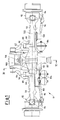
- Figure 1 shows a top plan view of an embodiment of the axle according to the present invention;
- Figure 2 shows a front elevation view of the axle of Figure 1;
- Figure 3 shows a rear elevation view of one portion of the axle of Figure 1;
- Figure 4 shows an enlarged cross section, according to the line IV-IV of Figure 1, of the axle in accordance with the present invention.
-
- With particular reference to the above figures, illustrated therein is a first embodiment of a damped suspended axle, in particular for use in agricultural machines, industrial vehicles and the like, the axle as a whole being designated by the
reference number 11. - The
axle 11 comprises atop support 62 consisting of a toptubular end 64 at the sides of which are integrally fixed twoplates 66 which extend and join together to identify a bracket-like extension 68. - The
extension 68 carries, at one free end,ribbings 82 which support, in a rotatable way, afirst pin 70. Thepin 70 projects and, at each one of its ends, carries, in an integral way, anarm 72 terminating with afork 74. Each of the twoforks 74 is pivoted to anend 76 which extends from anarm 78 that is integral with the hollowcentral body 80 of theaxle 11. Thecentral body 80 and thearms 78 make up a load-bearing element of theaxle 11. - In a position corresponding to the
extension 68 are moreover providedribbings 82 having a through hole in which asecond pin 84 is inserted. Also thesecond pin 84 projects from theribbings 82 and carries, integral with each one of its two ends, anarm 86 set above acorresponding arm 72. Each of the twoarms 86, in turn, terminates with afork 88 which is pivoted to anend 90. Of course, also the twoends 90 extend from eacharm 78, which is integral with thecentral body 80. - At the end of each of the
arms 78, theaxle 11 carries a steeringwheel hub assembly 92 from which there projects alever 94 to which is connected an articulatedrod 96. The articulatedrod 96 can be actuated in translation by asteering actuator 98, in such a way as to control steering of the two wheel-hub assemblies 92. - Inserted in the top
tubular end 64 is apin 100 by means of which theaxle 11 is anchored to the chassis of an agricultural machine or industrial vehicle. - On the
same pin 100, on one of its portions that projects on the side of theextension 68, is fixed a ball-and-socket joint 102 which is integral with arod 104 of a shock-absorber. - The
rod 104 passes through an opening 106 of thesupport 62 and inserts inside acylinder 108. The latter is, in turn, pivoted to oneend 110 which extends from thecentral body 80 of theaxle 11 at a point corresponding to an axis ofsymmetry 112 of the latter. Theend 110 is set between the twoarms 72. - The
cylinder 108 is connected to gas-charged accumulators 114 by means of pipes (not shown for reasons of simplicity). As may be clearly seen in Figures 1 and 3, theaccumulators 114 are three in number, one of a larger size and two of a smaller size. The two smaller-sized accumulators 114 are supported by avalve assembly 116, which is in turn supported by one of thearms 78 of theaxle 11. The remaining larger-sized accumulator 114 is instead directly fixed to thearm 78 of theaxle 11. In a position adjacent to the larger-sizedaccumulator 114 is fixed anelectronic control unit 120 which controls opening and/or closing of solenoid valves (not shown) designed to set thecylinder 108 in communication with theaccumulators 114 and with the hydraulic circuit of the machine or vehicle. - Operation of the damped suspended
axle 11, in particular for agricultural machines, industrial vehicles and the like, according to the present invention, is basically as described in what follows. - The
axle 11 is anchored underneath the chassis of the agricultural machine or industrial vehicle by means of thepin 100. - When the
axle 11 is mounted underneath the chassis of the vehicle, it can be operated in two different modes. - According to a first operating mode, the
cylinder 108 does not have oil under pressure in its chambers, and therod 104 comes down, bringing the piston that is integral with therod 104 into contact with the bottom of thecylinder 108. - In this situation, the
axle 11 operates as a traditional axle, being able only to oscillate or swing about thepin 100. - According to a second operating mode, instead, fluid under pressure is introduced into the two chambers of the
cylinder 108. - In this case, any stresses on the chassis of the machine or vehicle or on the
axle 11 itself move therod 104 in one of two directions, either towards the inside or towards the outside of thecylinder 108. - In this situation, the
arms pins arms 78 and thecentral body 80 to translate substantially parallel to one another. At the same time, the oil contained in thecylinder 108, passing into the gas-charged accumulators, dampens the oscillations. - In practice, the
arms 78 and thecentral body 80 translate along theaxis 112, with very limited, and anyway practically negligible, rotations about atransverse axis 122 or about another axis parallel to theaxis 122. - Modifications and variations to the
axle 11 according to the present invention, in addition to the ones already mentioned, are of course possible. - In particular, a second embodiment of the
axle 11, not illustrated for reasons of simplicity, is similar to the one previously described and differs from it in that it is provided with two shock-absorbing elements. - Maintaining the same reference numbers as for the first embodiment of the invention, at the tubular top end are fixed two attachment points, and to these are connected the
rods 104 of the shock-absorbing element. Therods 104 are inserted inside thecylinders 108 that traverse theforks arms 78. - In addition, besides being set at the front of the
axle 11 according to the invention, when the latter is mounted on a machine or vehicle, the shock-absorbing elements or hydraulic cylinders may be set also at the rear, without the operation of theaxle 11 according to the invention undergoing substantial modifications. In these cases, thetubular top end 64 has two attachment points to which the top ends of the shock-absorbing elements are fixed by means of ball-and-socket joints. - Obviously the operation of the
axle 11 according to the second embodiment is the same as already described for the first embodiment. - In practice, it has been noted that the damped suspended axle according to the invention, in particular for use on agricultural machines, industrial vehicles and the like, is particularly advantageous in so far as it is very safe and ensures a high degree of driving comfort for the driver, together with a very limited fatigue.
- In addition, the very compact assembly of auxiliary elements, all of which, on the other hand, are integral with the axle, enables easy accessibility to the said auxiliary elements and a reduction in overall dimensions, as well as guaranteeing a high level of reliability.
- The damped suspended axle, in particular for agricultural machines, industrial vehicles and the like, as it is conceived, may undergo numerous additional modifications and variations, all falling within the scope of the present invention. Furthermore, all the items may be replaced with others that are technically equivalent.
- In practice, the materials used, as well as the dimensions, may be any whatsoever according to the technical requirements.
Claims (11)
- A damped suspended axle (11), in particular for agricultural machines, industrial vehicles and the like, comprising a support (62) designed to be fixed to the chassis of said agricultural machine or industrial vehicle, said support (62) being connected to a load-bearing element (78, 80) for wheels, characterized in that said support (62) is connected in an articulated way to said load-bearing element (78, 80), and in that, set between the two, is at least one shock-absorbing element (104, 108), in such a way that any stresses that may act on said chassis or on said axle (11) will cause oscillations of said load-bearing element (78, 80) with respect to said support (62), said oscillations being damped by said shock-absorbing element (104, 108).
- A damped suspended axle (11) according to Claim 1, characterized in that said support (62) has at least one extension (68) to which are pivoted ends of first arms (72) and, set above these, ends of second arms (86), said first and second arms (72, 86) having second ends pivoted to said load-bearing element (78, 80).
- A damped suspended axle (11) according to Claim 2, characterized in that both said first arms (72) and said second arms (86) are two in number.
- A damped suspended axle (11) according to Claim 3, characterized in that both said first arms (72) and said second arms (86) have, at their second ends, a fork (74, 88) pivoted to at least one end (76, 90) of said load-bearing element (78, 80).
- A damped suspended axle (11) according to Claim 2, characterized in that said support (62) comprises at least one tubular top end (64) with which said extension (68) is integral, there projecting from said tubular top end (64) a second pin (100) to which is connected an end of a rod (104) of said shock-absorbing element (104, 108).
- A damped suspended axle (11) according to Claim 5, characterized in that said extension (68) develops towards a front part of said axle (11), in a situation in which the said axle (11) is mounted on a machine or vehicle, and, in the same way, said second pin (100) projects from a front part of said axle (11).
- A damped suspended axle (11) according to Claim 6, characterized in that a cylinder (108) of said shock-absorbing element (104, 108) is pivoted at one end (110) set between said first arms (72).
- A damped suspended axle (11) according to Claim 5, characterized in that one first end of said shock-absorbing element (104, 108) is connected to said pin (100) projecting from said tubular element (64) at least by means of a ball-and-socket joint (44, 102).
- A damped suspended axle (11) according to Claim 1, characterized in that it supports at least one valve assembly (116), which in turn supports at least one gas-charged accumulator (114) associated to said shock-absorbing element (104, 108).
- A damped suspended axle (11) according to Claim 9, characterized in that said arm (78) of said axle (11) supports at least one electronic control unit (120).
- A damped suspended axle (11) according to Claim 1, characterized in that said shock-absorbing element comprises at least one hydraulic cylinder (108) associated to a rod (104).
Priority Applications (7)
| Application Number | Priority Date | Filing Date | Title |
|---|---|---|---|
| DE60125320T DE60125320T2 (en) | 2001-02-23 | 2001-02-23 | Damped, sprung axle, in particular for agricultural machines, industrial vehicles and the like |
| DK01200674T DK1234696T3 (en) | 2001-02-23 | 2001-02-23 | Damped suspension shaft, especially for agricultural machinery, industrial vehicles and the like |
| ES01200674T ES2277885T3 (en) | 2001-02-23 | 2001-02-23 | SHAMPED SUSPENDED SHAFT, IN PARTICULAR FOR AGRICULTURAL MACHINES, INDUSTRIAL AND SIMILAR VEHICLES. |
| AT01200674T ATE348719T1 (en) | 2001-02-23 | 2001-02-23 | DAMPED, SUSPENSION AXLE, ESPECIALLY FOR AGRICULTURAL MACHINES, INDUSTRIAL VEHICLES AND THE LIKE |
| EP01200674A EP1234696B1 (en) | 2001-02-23 | 2001-02-23 | Damped suspended axle, in particular for agricultural machines, industrial vehicles and the like |
| PT01200674T PT1234696E (en) | 2001-02-23 | 2001-02-23 | Damped suspended axle, in particular for agricultural machines, industrial vehicles and the like |
| CY20071100345T CY1108003T1 (en) | 2001-02-23 | 2007-03-13 | ABSOLUTELY Hanging axle, SPECIFICALLY FOR AGRICULTURAL MACHINERY, INDUSTRIAL VEHICLES |
Applications Claiming Priority (1)
| Application Number | Priority Date | Filing Date | Title |
|---|---|---|---|
| EP01200674A EP1234696B1 (en) | 2001-02-23 | 2001-02-23 | Damped suspended axle, in particular for agricultural machines, industrial vehicles and the like |
Publications (2)
| Publication Number | Publication Date |
|---|---|
| EP1234696A1 true EP1234696A1 (en) | 2002-08-28 |
| EP1234696B1 EP1234696B1 (en) | 2006-12-20 |
Family
ID=8179934
Family Applications (1)
| Application Number | Title | Priority Date | Filing Date |
|---|---|---|---|
| EP01200674A Expired - Lifetime EP1234696B1 (en) | 2001-02-23 | 2001-02-23 | Damped suspended axle, in particular for agricultural machines, industrial vehicles and the like |
Country Status (7)
| Country | Link |
|---|---|
| EP (1) | EP1234696B1 (en) |
| AT (1) | ATE348719T1 (en) |
| CY (1) | CY1108003T1 (en) |
| DE (1) | DE60125320T2 (en) |
| DK (1) | DK1234696T3 (en) |
| ES (1) | ES2277885T3 (en) |
| PT (1) | PT1234696E (en) |
Cited By (1)
| Publication number | Priority date | Publication date | Assignee | Title |
|---|---|---|---|---|
| EP2985160A1 (en) * | 2014-08-14 | 2016-02-17 | Deere & Company | Front axle suspension for a work vehicle |
Families Citing this family (1)
| Publication number | Priority date | Publication date | Assignee | Title |
|---|---|---|---|---|
| DE102006053572B3 (en) * | 2006-11-14 | 2008-07-03 | Kiekert Ag | Sensor for protecting e.g. person against jam in opening locked by e.g. sliding door of vehicle, has conductive reference potential layer electrically isolated from reflective layer and provided on side opposite to electrode |
Citations (5)
| Publication number | Priority date | Publication date | Assignee | Title |
|---|---|---|---|---|
| US4418932A (en) * | 1980-10-24 | 1983-12-06 | Iowa State University Research Foundation, Inc. | Front axle suspension system for a vehicle chassis |
| EP0512550A2 (en) * | 1991-05-10 | 1992-11-11 | Deere & Company | Spring suspension of a steering axle |
| EP0553516A1 (en) * | 1992-01-29 | 1993-08-04 | Carraro S.P.A. | A sprung axle assembly for a vehicle |
| EP0887212A1 (en) * | 1997-06-27 | 1998-12-30 | NEW HOLLAND ITALIA S.p.A. | Off-road vehicle front wheel suspension |
| EP0997328A1 (en) * | 1998-10-15 | 2000-05-03 | Carraro S.P.A. | A suspension system with an oscillating, rigid axle, particularly for tractors |
-
2001
- 2001-02-23 EP EP01200674A patent/EP1234696B1/en not_active Expired - Lifetime
- 2001-02-23 DK DK01200674T patent/DK1234696T3/en active
- 2001-02-23 PT PT01200674T patent/PT1234696E/en unknown
- 2001-02-23 DE DE60125320T patent/DE60125320T2/en not_active Expired - Lifetime
- 2001-02-23 AT AT01200674T patent/ATE348719T1/en active
- 2001-02-23 ES ES01200674T patent/ES2277885T3/en not_active Expired - Lifetime
-
2007
- 2007-03-13 CY CY20071100345T patent/CY1108003T1/en unknown
Patent Citations (5)
| Publication number | Priority date | Publication date | Assignee | Title |
|---|---|---|---|---|
| US4418932A (en) * | 1980-10-24 | 1983-12-06 | Iowa State University Research Foundation, Inc. | Front axle suspension system for a vehicle chassis |
| EP0512550A2 (en) * | 1991-05-10 | 1992-11-11 | Deere & Company | Spring suspension of a steering axle |
| EP0553516A1 (en) * | 1992-01-29 | 1993-08-04 | Carraro S.P.A. | A sprung axle assembly for a vehicle |
| EP0887212A1 (en) * | 1997-06-27 | 1998-12-30 | NEW HOLLAND ITALIA S.p.A. | Off-road vehicle front wheel suspension |
| EP0997328A1 (en) * | 1998-10-15 | 2000-05-03 | Carraro S.P.A. | A suspension system with an oscillating, rigid axle, particularly for tractors |
Cited By (4)
| Publication number | Priority date | Publication date | Assignee | Title |
|---|---|---|---|---|
| EP2985160A1 (en) * | 2014-08-14 | 2016-02-17 | Deere & Company | Front axle suspension for a work vehicle |
| CN105365511A (en) * | 2014-08-14 | 2016-03-02 | 迪尔公司 | Axle suspension |
| US9428025B2 (en) | 2014-08-14 | 2016-08-30 | Deere & Company | Axle suspension |
| CN105365511B (en) * | 2014-08-14 | 2019-06-28 | 迪尔公司 | Axle suspension device |
Also Published As
| Publication number | Publication date |
|---|---|
| ATE348719T1 (en) | 2007-01-15 |
| EP1234696B1 (en) | 2006-12-20 |
| CY1108003T1 (en) | 2013-09-04 |
| DK1234696T3 (en) | 2007-04-10 |
| DE60125320D1 (en) | 2007-02-01 |
| PT1234696E (en) | 2007-03-30 |
| DE60125320T2 (en) | 2007-07-12 |
| ES2277885T3 (en) | 2007-08-01 |
Similar Documents
| Publication | Publication Date | Title |
|---|---|---|
| KR101500415B1 (en) | Coupled torsion beam axle type suspension system | |
| EP1226985B1 (en) | Suspended axle of the articulated-connection type for industrial vehicles | |
| CN104129251A (en) | Dependent six-connecting rod suspension structure for vehicle | |
| CN214057156U (en) | Rear independent suspension structure | |
| CN102501897B (en) | Follow-up steering mechanism and independent suspension support bridge using same | |
| RU2487018C2 (en) | Stabiliser system for wheel axle suspension, and stabiliser | |
| CN108263161A (en) | Tilting vehicle | |
| US5088570A (en) | Steerable rear dual axle system for large trucks | |
| KR100348506B1 (en) | Structure for supporting fluid pressure cylinders used to control pivoting of vehicle axles | |
| EP1108569B1 (en) | Suspended rigid axle | |
| EP1234696B1 (en) | Damped suspended axle, in particular for agricultural machines, industrial vehicles and the like | |
| JP2000006624A (en) | Body frame for industrial vehicle and industrial vehicle | |
| EP1234695A1 (en) | Damped suspended axle, in particular for agricultural machines, industrial vehicles and the like | |
| KR100667431B1 (en) | Lateral links for vehicle suspension | |
| JPH0811516A (en) | Vehicle stabilizer device | |
| CN118254514A (en) | Vehicle chassis and vehicles | |
| KR100650320B1 (en) | Rear wheel toe control of vehicle | |
| RU2333844C2 (en) | Transverse stability stabiliser flexible con-rod | |
| US5308105A (en) | Steerable dual rear axle system for large vehicles | |
| JPH06312613A (en) | Suspension | |
| KR20080109965A (en) | Multi-link type rear suspension | |
| KR100643964B1 (en) | Rear wheel suspension structure | |
| KR100290949B1 (en) | Mounting structure of the rear axle suspension of automobile | |
| US20130113197A1 (en) | Transaxle assembly for mounting direct drive axles to a backbone frame | |
| ITMI992215A1 (en) | SUSPENDED AXLE CUSHIONED IN PARTICULAR FOR AGRICULTURAL MACHINES INDUSTRIAL VEHICLES AND SIMILAR |
Legal Events
| Date | Code | Title | Description |
|---|---|---|---|
| PUAI | Public reference made under article 153(3) epc to a published international application that has entered the european phase |
Free format text: ORIGINAL CODE: 0009012 |
|
| AK | Designated contracting states |
Kind code of ref document: A1 Designated state(s): AT BE CH CY DE DK ES FI FR GB GR IE IT LI LU MC NL PT SE TR |
|
| AX | Request for extension of the european patent |
Free format text: AL;LT;LV;MK;RO;SI |
|
| 17P | Request for examination filed |
Effective date: 20021017 |
|
| 17Q | First examination report despatched |
Effective date: 20030403 |
|
| AKX | Designation fees paid |
Designated state(s): AT BE CH CY DE DK ES FI FR GB GR IE IT LI LU MC NL PT SE TR |
|
| GRAP | Despatch of communication of intention to grant a patent |
Free format text: ORIGINAL CODE: EPIDOSNIGR1 |
|
| GRAS | Grant fee paid |
Free format text: ORIGINAL CODE: EPIDOSNIGR3 |
|
| GRAA | (expected) grant |
Free format text: ORIGINAL CODE: 0009210 |
|
| AK | Designated contracting states |
Kind code of ref document: B1 Designated state(s): AT BE CH CY DE DK ES FI FR GB GR IE IT LI LU MC NL PT SE TR |
|
| PG25 | Lapsed in a contracting state [announced via postgrant information from national office to epo] |
Ref country code: IT Free format text: LAPSE BECAUSE OF FAILURE TO SUBMIT A TRANSLATION OF THE DESCRIPTION OR TO PAY THE FEE WITHIN THE PRESCRIBED TIME-LIMIT;WARNING: LAPSES OF ITALIAN PATENTS WITH EFFECTIVE DATE BEFORE 2007 MAY HAVE OCCURRED AT ANY TIME BEFORE 2007. THE CORRECT EFFECTIVE DATE MAY BE DIFFERENT FROM THE ONE RECORDED. Effective date: 20061220 |
|
| REG | Reference to a national code |
Ref country code: GB Ref legal event code: FG4D |
|
| REG | Reference to a national code |
Ref country code: CH Ref legal event code: EP |
|
| REF | Corresponds to: |
Ref document number: 60125320 Country of ref document: DE Date of ref document: 20070201 Kind code of ref document: P |
|
| REG | Reference to a national code |
Ref country code: IE Ref legal event code: FG4D |
|
| REG | Reference to a national code |
Ref country code: PT Ref legal event code: SC4A Free format text: AVAILABILITY OF NATIONAL TRANSLATION Effective date: 20070316 |
|
| REG | Reference to a national code |
Ref country code: SE Ref legal event code: TRGR |
|
| REG | Reference to a national code |
Ref country code: DK Ref legal event code: T3 |
|
| REG | Reference to a national code |
Ref country code: CH Ref legal event code: NV Representative=s name: AMMANN PATENTANWAELTE AG BERN |
|
| REG | Reference to a national code |
Ref country code: GR Ref legal event code: EP Ref document number: 20070400825 Country of ref document: GR |
|
| ET | Fr: translation filed | ||
| REG | Reference to a national code |
Ref country code: ES Ref legal event code: FG2A Ref document number: 2277885 Country of ref document: ES Kind code of ref document: T3 |
|
| PLBE | No opposition filed within time limit |
Free format text: ORIGINAL CODE: 0009261 |
|
| STAA | Information on the status of an ep patent application or granted ep patent |
Free format text: STATUS: NO OPPOSITION FILED WITHIN TIME LIMIT |
|
| 26N | No opposition filed |
Effective date: 20070921 |
|
| PGFP | Annual fee paid to national office [announced via postgrant information from national office to epo] |
Ref country code: NL Payment date: 20140226 Year of fee payment: 14 Ref country code: LU Payment date: 20140305 Year of fee payment: 14 Ref country code: MC Payment date: 20140203 Year of fee payment: 14 Ref country code: IE Payment date: 20140227 Year of fee payment: 14 Ref country code: CH Payment date: 20140227 Year of fee payment: 14 Ref country code: DK Payment date: 20140225 Year of fee payment: 14 |
|
| PGFP | Annual fee paid to national office [announced via postgrant information from national office to epo] |
Ref country code: ES Payment date: 20140226 Year of fee payment: 14 Ref country code: BE Payment date: 20140228 Year of fee payment: 14 Ref country code: GR Payment date: 20140227 Year of fee payment: 14 |
|
| PGFP | Annual fee paid to national office [announced via postgrant information from national office to epo] |
Ref country code: PT Payment date: 20140206 Year of fee payment: 14 |
|
| PGFP | Annual fee paid to national office [announced via postgrant information from national office to epo] |
Ref country code: CY Payment date: 20140203 Year of fee payment: 14 |
|
| PG25 | Lapsed in a contracting state [announced via postgrant information from national office to epo] |
Ref country code: BE Free format text: LAPSE BECAUSE OF NON-PAYMENT OF DUE FEES Effective date: 20150228 |
|
| REG | Reference to a national code |
Ref country code: PT Ref legal event code: MM4A Free format text: LAPSE DUE TO NON-PAYMENT OF FEES Effective date: 20150824 |
|
| REG | Reference to a national code |
Ref country code: NL Ref legal event code: V1 Effective date: 20150901 |
|
| REG | Reference to a national code |
Ref country code: DK Ref legal event code: EBP Effective date: 20150228 |
|
| PG25 | Lapsed in a contracting state [announced via postgrant information from national office to epo] |
Ref country code: NL Free format text: LAPSE BECAUSE OF NON-PAYMENT OF DUE FEES Effective date: 20150901 Ref country code: LU Free format text: LAPSE BECAUSE OF NON-PAYMENT OF DUE FEES Effective date: 20150223 |
|
| REG | Reference to a national code |
Ref country code: CH Ref legal event code: PL |
|
| PG25 | Lapsed in a contracting state [announced via postgrant information from national office to epo] |
Ref country code: LI Free format text: LAPSE BECAUSE OF NON-PAYMENT OF DUE FEES Effective date: 20150228 Ref country code: PT Free format text: LAPSE BECAUSE OF NON-PAYMENT OF DUE FEES Effective date: 20150824 Ref country code: CH Free format text: LAPSE BECAUSE OF NON-PAYMENT OF DUE FEES Effective date: 20150228 Ref country code: MC Free format text: LAPSE BECAUSE OF NON-PAYMENT OF DUE FEES Effective date: 20150302 Ref country code: CY Free format text: LAPSE BECAUSE OF NON-PAYMENT OF DUE FEES Effective date: 20150223 |
|
| REG | Reference to a national code |
Ref country code: GR Ref legal event code: ML Ref document number: 20070400825 Country of ref document: GR Effective date: 20150902 |
|
| REG | Reference to a national code |
Ref country code: IE Ref legal event code: MM4A |
|
| PG25 | Lapsed in a contracting state [announced via postgrant information from national office to epo] |
Ref country code: GR Free format text: LAPSE BECAUSE OF NON-PAYMENT OF DUE FEES Effective date: 20150902 |
|
| PG25 | Lapsed in a contracting state [announced via postgrant information from national office to epo] |
Ref country code: IE Free format text: LAPSE BECAUSE OF NON-PAYMENT OF DUE FEES Effective date: 20150223 Ref country code: DK Free format text: LAPSE BECAUSE OF NON-PAYMENT OF DUE FEES Effective date: 20150228 |
|
| REG | Reference to a national code |
Ref country code: FR Ref legal event code: PLFP Year of fee payment: 16 |
|
| REG | Reference to a national code |
Ref country code: ES Ref legal event code: FD2A Effective date: 20160329 |
|
| PG25 | Lapsed in a contracting state [announced via postgrant information from national office to epo] |
Ref country code: ES Free format text: LAPSE BECAUSE OF NON-PAYMENT OF DUE FEES Effective date: 20150224 |
|
| REG | Reference to a national code |
Ref country code: FR Ref legal event code: PLFP Year of fee payment: 17 |
|
| REG | Reference to a national code |
Ref country code: FR Ref legal event code: PLFP Year of fee payment: 18 |
|
| PGFP | Annual fee paid to national office [announced via postgrant information from national office to epo] |
Ref country code: FI Payment date: 20200227 Year of fee payment: 20 Ref country code: SE Payment date: 20200227 Year of fee payment: 20 Ref country code: GB Payment date: 20200227 Year of fee payment: 20 Ref country code: AT Payment date: 20200203 Year of fee payment: 20 Ref country code: DE Payment date: 20200227 Year of fee payment: 20 |
|
| PGFP | Annual fee paid to national office [announced via postgrant information from national office to epo] |
Ref country code: TR Payment date: 20200207 Year of fee payment: 20 Ref country code: FR Payment date: 20200225 Year of fee payment: 20 |
|
| REG | Reference to a national code |
Ref country code: DE Ref legal event code: R071 Ref document number: 60125320 Country of ref document: DE |
|
| REG | Reference to a national code |
Ref country code: GB Ref legal event code: PE20 Expiry date: 20210222 |
|
| REG | Reference to a national code |
Ref country code: FI Ref legal event code: MAE |
|
| REG | Reference to a national code |
Ref country code: SE Ref legal event code: EUG |
|
| REG | Reference to a national code |
Ref country code: AT Ref legal event code: MK07 Ref document number: 348719 Country of ref document: AT Kind code of ref document: T Effective date: 20210223 |
|
| PG25 | Lapsed in a contracting state [announced via postgrant information from national office to epo] |
Ref country code: GB Free format text: LAPSE BECAUSE OF EXPIRATION OF PROTECTION Effective date: 20210222 |