EP1234614A1 - Metering vessel subdivided by ribs for receiving reagents, its fabrication and use - Google Patents
Metering vessel subdivided by ribs for receiving reagents, its fabrication and use Download PDFInfo
- Publication number
- EP1234614A1 EP1234614A1 EP01104779A EP01104779A EP1234614A1 EP 1234614 A1 EP1234614 A1 EP 1234614A1 EP 01104779 A EP01104779 A EP 01104779A EP 01104779 A EP01104779 A EP 01104779A EP 1234614 A1 EP1234614 A1 EP 1234614A1
- Authority
- EP
- European Patent Office
- Prior art keywords
- container
- container according
- reagents
- chambers
- cover
- Prior art date
- Legal status (The legal status is an assumption and is not a legal conclusion. Google has not performed a legal analysis and makes no representation as to the accuracy of the status listed.)
- Withdrawn
Links
Images

Classifications
-
- B—PERFORMING OPERATIONS; TRANSPORTING
- B01—PHYSICAL OR CHEMICAL PROCESSES OR APPARATUS IN GENERAL
- B01L—CHEMICAL OR PHYSICAL LABORATORY APPARATUS FOR GENERAL USE
- B01L3/00—Containers or dishes for laboratory use, e.g. laboratory glassware; Droppers
- B01L3/54—Labware with identification means
- B01L3/545—Labware with identification means for laboratory containers
-
- Y—GENERAL TAGGING OF NEW TECHNOLOGICAL DEVELOPMENTS; GENERAL TAGGING OF CROSS-SECTIONAL TECHNOLOGIES SPANNING OVER SEVERAL SECTIONS OF THE IPC; TECHNICAL SUBJECTS COVERED BY FORMER USPC CROSS-REFERENCE ART COLLECTIONS [XRACs] AND DIGESTS
- Y10—TECHNICAL SUBJECTS COVERED BY FORMER USPC
- Y10T—TECHNICAL SUBJECTS COVERED BY FORMER US CLASSIFICATION
- Y10T436/00—Chemistry: analytical and immunological testing
- Y10T436/25—Chemistry: analytical and immunological testing including sample preparation
Definitions
- the invention relates to a container for holding reagents for analysis with various analytical methods, a method of manufacturing a measuring vessel a measuring vessel and the use of such a measuring vessel.
- a known method for measuring the coagulation properties of blood is the coagulation by measuring a Relative movement of a cuvette containing a blood sample determined relative to a stamp. To perform various Tests on the blood sample will test this one or more Reagents added.
- the reagents are usually in in liquid form and are used by those performing the tests Laboratories or hospitals kept in large quantities. Often, the entire stock quantity is not used for a test series of reagent consumed so that the reagent expires, which is uneconomical. This problem also occurs with others especially medical, biochemical, environmental or food analysis methods.
- the object is achieved by a container according to claim 1, a method according to claim 14, a measuring vessel according to claim 16 and the use of such Claim 17 or 18.
- An essential aspect of the invention is that for the required amount of reagents directly in the test Container is made available.
- the reagents can in solid form, e.g. dried or lyophilized.
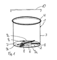
- the container according to the invention 1 designed as a cuvette in a first embodiment.
- a cuvette can be used, for example, in a device for measuring the coagulation properties of blood or other test liquids.
- the cuvette points a substantially flat bottom 2 and one of them extending cylindrical wall 3 with an upper edge 4.
- a support 6 on the bottom 2 formed on which a rod-shaped magnetic stirrer or Stirring fish 7 made of stainless steel or soft iron rests.
- the in Fig. 1 embodiment extend from the Pad 6 from in the radial direction to the cylinder wall 3 in essentially straight webs 8, by the adjacent on the floor Chambers 9a, 9b, 9c are formed.
- the height the webs are small in relation to the height of the cylinder wall.
- the height of the webs is only about 1 mm. at an inner diameter of the cuvette of about 0.8 cm the volume of the available for the reagents Chambers about 15-20 ⁇ l.
- the amount of edition 6 is so much greater than the height of the webs 8 that the agitator fish 7th can rotate freely.
- a drive for the stir fish is not shown electric motor provided.
- the control of the Stirring device is continuous or pulsed.
- the cuvette is made of a material that is the reagents to be introduced and the blood or test liquid is not attacked, for example made of plastic.
- the support 6 and the webs 8 are preferably integrated formed with the cell bottom 2.
- the cuvette has a lid 10 at its open end closable.
- a first Step the reagents 12, 13, 14 into the chambers 9a, 9b, 9c on the cell bottom 2 by means of a multiple compartment dispenser or one Automatic pipetting machines in the required quantities at a few ⁇ l lie, filled, with a confluence of the Reagents is prevented by the webs 8. Subsequently the reagent drops are dried in the cuvette or lyophilized.
- the dried or lyophilized Reagents as shown in Fig. 3 by which Filling the blood sample 15 itself or by previous dissolving dissolved with water using a pipette 16.
- the cuvette is then in the device for measuring the coagulation properties used, a stamp 11 in the sample dips.
- the coagulation properties are measured then in a known manner by measuring the relative rotational movement the stamp to the cuvette.
- the blood sample 15 is mixed with the reagents 12, 13, 14 by the movement of the stirring fish 7.
- the cylindrical shape for the method of measuring the coagulation properties of blood or other test fluid suitable for the relative movement of the cuvette and stamp the shape of the cuvette does not have to be used for other analysis methods be cylindrical.
- the cuvette has flat side surfaces.
- the floor can also be concave, for example.
- An appropriate number of webs that create the chambers is depending on the application or the number of reagents required. Their height depends on the required chamber volume and the number of reagents required.
- the Pad 6 with the stirring fish 7 is not absolutely necessary, but beneficial. For some applications, a stir fish not necessarily required.
- the cuvette has a shoulder 17 on its side wall, which is used to grip and position the cuvette and which a code, for example a barcode and / or color code for labeling the cuvette.
- a code for example a barcode and / or color code for labeling the cuvette.
- the Bridges are not straight, but curved, e.g. curled or propeller-shaped, trained, causing the dissolution of the in the reagents contained in the chambers by an additional Swirling can be improved.
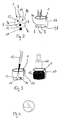
- the invention is the cover 100 formed with a central opening 101, as in Fig. 5, in which a closure element in the form of a lyophilization stopper 102, as shown in FIG. 6, can be used is.
- the lyophilization stopper 102 has a head 103 with a diameter that is larger than the diameter of the Opening 101 so that the head completely covers the opening can, and a closure portion 104 for insertion into the Opening 101 and to close the same.
- the outside diameter of the head 103 is e.g. as large as the outside diameter of the cover so that the stopper is in place Condition flush with the lid on the outside.
- the outside diameter of the closure section is such that the closure section 104 just fits through the opening 101 and closes it.
- the closure portion 104 is slotted formed, with a slot 105 that starts out from a distance from the head 103 to the one opposite the head End of the closure portion extends.
- a slot 105 that starts out from a distance from the head 103 to the one opposite the head End of the closure portion extends.
- two legs 106, 107 are formed, the relative are elastically bendable to a certain extent.
- On The slot 105 has its end facing away from the head 103 a cylindrical widening 108 with a diameter, about the diameter of the stir bar or stir bar 7 corresponds to receiving the stir bar 7. Due to the Elasticity of the legs is the stir bar 7 in the closure part clamped.
- the length of the stir bar is greater than the diameter of the opening 101 in the lid 100.
- the Lyophilization stopper 102 through the opening 101 of the lid performed or pressed into the lid when the lid not yet placed on the cuvette or container 1 is.
- the impression takes place so far that there is still one Section 105a, 105b of the slot 105 above and below the lid 100 is located.
- the stir bar 7 between the legs of the plug jammed.
- the lid, together with the stopper and the clamped to it Stirring rod pressed onto the cuvette in which liquid reagents are already in the chambers.
- it will be lyophilization was carried out, vapors produced, 8 and 9, via the slot sections 105a, 105b can escape.
- the stopper as shown in Fig.
- the stirring rod is still held on the stopper.
- the the cuvette for example, is sealed in a bag welded, on which the expiry date is indicated.
- For use is withdrawn from the lyophilization stopper. there the stir bar falls into the cuvette. Through the now exposed The sample to be measured can be introduced through the opening.
- the cover according to the invention is not limited to this that together with a cuvette that described the above Combing is used. It can also be for others Serve measuring vessels that have no chambers.
- the advantage is that only one or two exact pipetting is required are. Furthermore, there is no loss of reagents and no deterioration of the reagents.
- the cuvette is easy to make, can be filled with a standard filling machine and in a conventional dryer or lyophilizer be put. Instead of the effort involved in manufacturing liquid reagents, especially in combinations, can Filling in separate form. This also makes it possible the easy handling of unstable substances such as different Enzymes that are often only elaborate in certain solutions Combinations can be stabilized.
- the production the cuvette is associated with only low costs.
- the application of the container 1 described above is not in the field of measuring coagulation properties of Limited blood or other test fluids.
- the container 1 can also be used for other analysis methods, for example in clinical or food analysis.
- a method according to the invention for producing a Measuring vessel for any analysis includes the provision of a container described above, the filling of the reagents into the appropriate chambers, drying or lyophilizing of the introduced reagents and the oversight of the Container with a lid, which can also be welded on, for example Foil can be formed.
- the so produced Measuring vessels can be provided in large quantities and allow the analysis to be carried out without stockpiling of liquid reagents.
- the invention serves Container as a combined reagent carrier and as Measuring vessel.
Landscapes
- Chemical & Material Sciences (AREA)
- Analytical Chemistry (AREA)
- Health & Medical Sciences (AREA)
- Clinical Laboratory Science (AREA)
- Chemical Kinetics & Catalysis (AREA)
- Investigating Or Analysing Biological Materials (AREA)
- Automatic Analysis And Handling Materials Therefor (AREA)
Abstract
Description
Die Erfindung betrifft einen Behälter zur Aufnahme von Reagenzien zur Analyse mit verschiedenen analytischen Verfahren, ein Verfahren zum Herstellen eines Meßgefäßes ein Meßgefäß und eine Verwendung eines solchen Meßgefäßes.The invention relates to a container for holding reagents for analysis with various analytical methods, a method of manufacturing a measuring vessel a measuring vessel and the use of such a measuring vessel.
In einem bekannten Verfahren zur Messung der Koagulationseigenschaften von Blut wird die Koagulation über Messung einer Relativbewegung einer eine Blutprobe enthaltende Küvette relativ zu einem Stempel ermittelt. Zum Durchführen verschiedener Tests an der Blutprobe werden dieser ein oder mehrere Reagenzien zugesetzt. Üblicherweise liegen die Reagenzien in flüssiger Form vor und werden von den die Tests vornehmenden Labors oder Krankenhäusern in größeren Mengen vorrätig gehalten. Oftmals wird für eine Testserie nicht die gesamte Vorratsmenge an Reagenz verbraucht, so daß das Reagenz verfällt, was unwirtschaftlich ist. Dieses Problem tritt auch bei anderen, insbesondere medizinischen, biochemischen, Umwelt- oder lebensmittelanalytischen Analyseverfahren auf. In a known method for measuring the coagulation properties of blood is the coagulation by measuring a Relative movement of a cuvette containing a blood sample determined relative to a stamp. To perform various Tests on the blood sample will test this one or more Reagents added. The reagents are usually in in liquid form and are used by those performing the tests Laboratories or hospitals kept in large quantities. Often, the entire stock quantity is not used for a test series of reagent consumed so that the reagent expires, which is uneconomical. This problem also occurs with others especially medical, biochemical, environmental or food analysis methods.
Es ist Aufgabe der Erfindung, einen Behälter zur Aufnahme von Reagenzien zur Analyse mit verschiedenen analytischen Verfahren, ein Verfahren zum Herstellen eines Meßgefäßes, ein Meßgefäß und eine Verwendung eines solchen Meßgefäßes bereitzustellen, das einfach zu handhabende Tests erlaubt und die Wirtschaftlichkeit der Tests erhöht.It is an object of the invention to provide a container for Reagents for analysis with various analytical methods, a method of manufacturing a measuring vessel, a measuring vessel and to provide use of such a measuring vessel, that allows easy to use tests and that Efficiency of the tests increased.
Die Aufgabe wird gelöst durch einen Behälter nach Patentanspruch
1, ein Verfahren nach Patentanspruch 14, ein Meßgefäß
nach Patentanspruch 16 und die Verwendung eines solchen nach
Patentanspruch 17 oder 18.The object is achieved by a container according to
Weiterbildungen der Erfindung sind in den Unteransprüchen angegeben.Developments of the invention are specified in the subclaims.
Ein wesentlicher Aspekt der Erfindung ist, daß die für den jeweiligen Test erforderliche Reagenzienmenge direkt in dem Behälter zur Verfügung gestellt wird. Die Reagenzien können in fester Form, z.B. getrocknet oder lyophilisiert vorliegen.An essential aspect of the invention is that for the required amount of reagents directly in the test Container is made available. The reagents can in solid form, e.g. dried or lyophilized.
Weitere Merkmale und Zweckmäßigkeiten der Erfindung ergeben sich aus der Beschreibung von Ausführungsbeispielen anhand der Figuren.Further features and advantages of the invention result themselves from the description of exemplary embodiments of the figures.
Von den Figuren zeigen:
- Fig. 1:
- eine schematische Ansicht des erfindungsgemäßen Behälters in einer ersten Ausführungsform;
- Fig. 2:
- eine schematische Darstellung der erfindungsgemäßen Herstellung eines Testgefäßes;
- Fig. 3:
- eine schematische Darstellung der Durchführung eines Tests;
- Fig. 4:
- eine Draufsicht auf den erfindungsgemäßen Behälter in einer weiteren Ausführungsform;
- Fig. 5:
- eine Draufsicht auf einen Deckel für den erfindungsgemäßen Behälter in einer weiteren Ausführungsform;
- Fig. 6:
- eine schematische perspektivische Ansicht eines Verschlußelements für den Deckel nach Fig. 5;
- Fig. 7:
- eine schematische Ansicht des Deckels von Fig. 5 mit eingesetztem Verschlußelement nach Fig. 6;
- Fig. 8:
- eine schematische Darstellung des Deckels mit Verschlußelement nach den Figuren 5 bis 7 in auf dem Behälter aufgesetztem Zustand;
- Fig. 9:
- eine schematische Darstellung der Wirkungsweise des Verschlußelements nach Fig. 6;
- Fig. 10:
- eine Ansicht des Behälters mit dem Deckel gemäß den Figuren 5 bis 9 in geschlossener Darstellung; und
- Fig. 11:
- eine Ansicht des Behälters mit Deckel gemäß Fig. 5 und entferntem Verschlußelement.
- Fig. 1:
- a schematic view of the container according to the invention in a first embodiment;
- Fig. 2:
- a schematic representation of the manufacture of a test vessel according to the invention;
- Fig. 3:
- a schematic representation of the implementation of a test;
- Fig. 4:
- a plan view of the container according to the invention in a further embodiment;
- Fig. 5:
- a plan view of a lid for the container according to the invention in a further embodiment;
- Fig. 6:
- is a schematic perspective view of a closure element for the lid of FIG. 5;
- Fig. 7:
- a schematic view of the lid of Figure 5 with inserted closure member of FIG. 6.
- Fig. 8:
- a schematic representation of the lid with closure element according to Figures 5 to 7 in the state placed on the container;
- Fig. 9:
- a schematic representation of the operation of the closure element of FIG. 6;
- Fig. 10:
- a view of the container with the lid according to Figures 5 to 9 in a closed representation; and
- Fig. 11:
- a view of the container with a lid according to FIG. 5 and the closure element removed.
Wie aus Fig. 1 ersichtlich ist, ist der erfindungsgemäße Behälter
1 in einer ersten Ausführungsform als Küvette ausgebildet.
Eine solche Küvette ist beispielsweise einsetzbar in
eine Vorrichtung zur Messung der Koagulationseigenschaften
von Blut oder anderen Testflüssigkeiten. Die Küvette weist
einen im wesentlichen ebenen Boden 2 und eine sich von diesem
erstreckende zylindrische Wand 3 mit einem oberen Rand 4 auf.
Im Inneren der Küvette ist auf dem Boden 2 eine Auflage 6
ausgebildet, auf der ein stabförmiger Magnet-Rührer bzw.
Rührfisch 7 aus Edelstahl oder Weicheisen ruht. In dem in
Fig. 1 gezeigten Ausführungsbeispiel erstrecken sich von der
Auflage 6 aus in radialer Richtung bis zur Zylinderwand 3 im
wesentlichen geradlinige Stege 8, durch die auf dem Boden aneinandergrenzende
Kammern 9a, 9b, 9c gebildet werden. Die Höhe
der Stege ist gering im Verhältnis zur Höhe der Zylinderwand.
Für die beschriebene Ausführungsform, bei der die Küvette
zur Messung der Koagulationseigenschaften von Blut eingesetzt
wird, beträgt die Höhe der Stege nur etwa 1 mm. Bei
einem Innendurchmesser der Küvette von etwa 0.8 cm beträgt
das für die Reagenzien zur Verfügung stehende Volumen der
Kammern etwa 15-20 µl. Die Höhe der Auflage 6 ist umsoviel
größer als die Höhe der Stege 8, daß sich der Rührfisch 7
frei drehen kann. Als Antrieb für den Rührfisch ist ein nicht
dargestellter Elektromotor vorgesehen. Die Ansteuerung der
Rühreinrichtung ist kontinuierlich oder gepulst.As can be seen from Fig. 1, the container according to the
Die Küvette ist aus einem Material gebildet, welches durch
die einzubringenden Reagenzien und das Blut bzw. die Testflüssigkeit
nicht angegriffen wird, beispielsweise aus Kunststoff.
Die Auflage 6 und die Stege 8 sind vorzugsweise integriert
mit dem Küvettenboden 2 gebildet.The cuvette is made of a material that is
the reagents to be introduced and the blood or test liquid
is not attacked, for example made of plastic.
The
An ihrem offenen Ende ist die Küvette mit einem Deckel 10
verschließbar.The cuvette has a
Im Betrieb werden wie in Fig. 2 gezeigt ist in einem ersten
Schritt die Reagenzien 12, 13, 14 in die Kammern 9a, 9b, 9c
am Küvettenboden 2 mittels eines Merfachdispensers bzw. eines
Pipettierautomaten in den erforderlichen Mengen, die bei wenigen
µl liegen, eingefüllt, wobei ein Zusammenfließen der
Reagenzien durch die Stege 8 verhindert wird. Anschließend
werden die eingebrachten Reagenztropfen in der Küvette getrocknet
oder lyophilisiert.In operation, as shown in Fig. 2, in a first
Step the
Zur Messung der Koagulationseigenschaften von Blut oder einer
anderen Testflüssigkeit, werden die getrockneten oder lyophilisierten
Reagenzien wie in Fig. 3 gezeigt ist, durch das
Einfüllen der Blutprobe 15 selbst oder durch vorheriges Anlösen
mit Wasser mittels einer Pipette 16 gelöst. Die Küvette
wird dann in die Vorrichtung zur Messung der Koagulationseigenschaften
eingesetzt, wobei ein Stempel 11 in die Probe
eintaucht. Die Messung der Koagulationseigenschaften erfolgt
dann in bekannter Weise durch Messung der relativen Drehbewegung
des Stempels zur Küvette. Vor und während der Messung
erfolgt eine Vermischung der Blutprobe 15 mit den Reagenzien
12, 13, 14 durch die Bewegung des Rührfischs 7.For measuring the coagulation properties of blood or a
other test liquid, the dried or lyophilized
Reagents as shown in Fig. 3 by which
Filling the
Abwandlungen des Behälters 1 sind möglich. Obwohl sich die
zylindrische Form für das Verfahren der Messung der Koagulationseigenschaften
von Blut oder einer anderen Testflüssigkeit
über die Relativbewegung von Küvette und Stempel eignet,
muß für andere Analyseverfahren die Form der Küvette nicht
unbedingt zylindrisch sein. Für eine Messung über die Bestimmung
der Absorption oder Fluoreszenz bzw. Lumineszenz hindurchgeleiteten
Lichts beispielsweise, ist es vorteilhaft,
daß die Küvette plane Seitenflächen aufweist. Der Boden kann
auch beispielsweise konkav gewölbt sein. Eine geeignete Anzahl
von Stegen, die die Kammern erzeugen, ist je nach Anwendungszweck
bzw. Anzahl der erforderlichen Reagenzien vorgesehen.
Ihre Höhe ist je nach dem erforderlichen Kammervolumen
sowie der Anzahl der erforderlichen Reagenzien ausgelegt. Die
Auflage 6 mit dem Rührfisch 7 ist nicht zwingend erforderlich,
aber vorteilhaft. Für einige Anwendungen ist ein Rührfisch
nicht unbedingt erforderlich. In einer Weiterbildung
weist die Küvette einen Ansatz 17 an ihrer Seitenwand auf,
der zum Greifen und Positionieren der Küvette dient und der
einen Code, beispielsweise einen Barcode und/oder Farbcode
zur Kennzeichnung der Küvette enthalten kann. Der Ansatz ist
so ausgebildet, daß durch ihn der Behälter in einer Meßeinrichtung
oder beim Abfüllen eindeutig positioniert wird und
dient somit als Positioniereinrichtung bzw. Anschlag.Modifications of the
In einer in Fig. 4 dargestellten Ausführungsform sind die Stege nicht geradlinig, sondern gekrümmt, z.B. gewellt oder propellerförmig, ausgebildet, wodurch die Auflösung der in den Kammern enthaltenen Reagenzien durch eine zusätzliche Verwirbelung verbessert werden kann.In an embodiment shown in Fig. 4, the Bridges are not straight, but curved, e.g. curled or propeller-shaped, trained, causing the dissolution of the in the reagents contained in the chambers by an additional Swirling can be improved.
In einer in den Figuren 5 bis 11 dargestellten weiteren Ausführungform
der Erfindung ist der Deckel bzw. die Abdeckung
100 mit einer zentralen Öffnung 101 ausgebildet, wie in Fig.
5 gezeigt ist, in die ein Verschlußelement in Form eines Lyophilisationsstopfens
102, wie in Fig. 6 gezeigt ist, einsetzbar
ist. Der Lyophilisationsstopfen 102 weist einen Kopf 103
mit einem Durchmesser, der größer ist als der Durchmesser der
Öffnung 101, so daß der Kopf die Öffnung vollständig abdecken
kann, und einen Verschlußabschnitt 104 zum Einsetzen in die
Öffnung 101 und zum Verschließen derselben, auf. Der Außendurchmesser
des Kopfes 103 ist z.B. so groß wie der Außendurchmesser
des Deckels, so daß der Stopfen in aufgesetztem
Zustand außen bündig mit dem Deckel abschließt. Der Außendurchmesser
des Verschlußabschnittes ist so, daß der Verschlußabschnitt
104 gerade durch die Öffnung 101 hindurchpaßt
und diese verschließt. Der Verschlußabschnitt 104 ist geschlitzt
ausgebildet, mit einem Schlitz 105, der sich ausgehend
von einem Abstand vom Kopf 103 bis an das dem Kopf gegenüberliegende
Ende des Verschlußabschnitts erstreckt. Durch
den Schlitz 105 sind zwei Schenkel 106, 107 gebildet, die relativ
zueinander in gewissem Maße elastisch biegbar sind. An
seinem dem Kopf 103 abgewandten Ende weist der Schlitz 105
eine zylindrische Verbreiterung 108 auf mit einem Durchmesser,
der etwa dem Durchmesser des Rührstabes bzw. Rührfisches
7 entspricht, zur Aufnahme des Rührstabes 7. Aufgrund der
Elastizität der Schenkel ist der Rührstab 7 in das Verschlußteil
einklemmbar. Die Länge des Rührstabes ist größer, als
der Durchmesser der Öffnung 101 in dem Deckel 100.In a further embodiment shown in FIGS. 5 to 11
the invention is the
Im Betrieb wird, wie in Fig. 7 dargestellt ist zuerst der
Lyophilisationsstopfen 102 durch die Öffnung 101 des Deckels
durchgeführt bzw. in den Deckel eingedrückt, wenn der Deckel
noch nicht auf die Küvette bzw. den Behälter 1 aufgesetzt
ist. Das Eindrücken erfolgt soweit, daß sich noch jeweils ein
Abschnitt 105a, 105b des Schlitzes 105 oberhalb bzw. unterhalb
des Deckels 100 befindet. Dann wird der Rührstab 7 zwischen
die Schenkel des Stopfens eingeklemmt. Anschließend
wird der Deckel mitsamt dem Stopfen und dem daran festgeklemmten
Rührstab auf die Küvette aufgepreßt, in der sich in
den Kammern bereits flüssige Reagenzien befinden. Dann wird
die Lyophilisation durchgeführt, wobei entstehende Dämpfe,
wie in Fig. 8 und 9 gezeigt ist, über die Schlitzabschnitte
105a, 105b entweichen können. Anschließend wird der Stopfen,
wie in Fig. 10 gezeigt ist zum Verschließen der Küvette ganz
in den Deckel eingedrückt, so daß der Schlitz 105 ganz innerhalb
des Behälters liegt und der Behälter verschlossen ist.
Dabei wird der Rührstab immer noch am Stopfen gehalten. Die
so verschlossene Küvette wird beispielsweise in eine Tüte
eingeschweißt, auf der das Verfallsdatum angegeben ist. Für
den Gebrauch wird der Lyophilisationsstopfen abgezogen. Dabei
fällt der Rührstab in die Küvette. Durch die nun freiliegende
Öffnung kann die zu messende Probe eingebracht werden.In operation, as shown in FIG. 7, the
Die erfindungsgemäße Abdeckung ist nicht darauf beschränkt daß sie zusammen mit einer Küvette, die die oben beschriebenen Kammen aufweist verwendet wird. Er kann auch für andere Meßgefäße dienen, die keine Kammern aufweisen. The cover according to the invention is not limited to this that together with a cuvette that described the above Combing is used. It can also be for others Serve measuring vessels that have no chambers.
Für die Messung der Koagulationseigenschaften von Blut weist die beschriebene Küvette und das beschriebene Verfahren den Vorteil auf, daß nur eine oder zwei exakte Pipettierungen erforderlich sind. Ferner treten keine Reagenzienverluste und kein Verderb der Reagenzien auf. Die Küvette ist einfach herzustellen, kann mit einer Standardabfüllungsmaschine befüllt werden und in einen herkömmlichen Trockner oder Lyophilisator gestellt werden. Anstelle des Aufwands bei der Herstellung flüssiger Reagenzien, insbesondere bei Kombinationen kann die Abfüllung in getrennter Form erfolgen. Dies ermöglicht auch die einfache Handhabung von labilen Substanzen wie z.B. verschiedenen Enzymen, die in Lösung oft nur aufwendig in bestimmten Kombinationen stabilisierbar sind. Die Herstellung der Küvette ist mit nur geringen Kosten verbunden.For measuring the coagulation properties of blood points the cuvette and the method described The advantage is that only one or two exact pipetting is required are. Furthermore, there is no loss of reagents and no deterioration of the reagents. The cuvette is easy to make, can be filled with a standard filling machine and in a conventional dryer or lyophilizer be put. Instead of the effort involved in manufacturing liquid reagents, especially in combinations, can Filling in separate form. This also makes it possible the easy handling of unstable substances such as different Enzymes that are often only elaborate in certain solutions Combinations can be stabilized. The production the cuvette is associated with only low costs.
Die Anwendung des oben beschriebenen Behälters 1 ist nicht
auf das Gebiet der Messung von Koagulationseigenschaften von
Blut oder anderen Testflüssigkeiten beschränkt. Der Behälter
1 kann auch für andere Analyseverfahren, beispielsweise in
der klinischen oder der Lebensmittelanalytik verwendet werden.
Ein erfindungsgemäßes Verfahren zum Herstellen eines
Meßgefäßes für beliebige Analysen umfaßt die Bereitstellung
eines oben beschriebenen Behälters, die Einfüllung der Reagenzien
in die entsprechenden Kammern, das Trocknen oder Lyophilisieren
der eingebrachten Reagenzien und das Versehen des
Behälters mit einem Deckel, der beipielsweise auch als aufgeschweißte
Folie ausgebildet sein kann. Die derart hergestellten
Meßgefäße können in größeren Mengen bereitgestellt werden
und erlauben die Durchführung der Analyse ohne das Vorrätighalten
von flüssigen Reagenzien. Somit dient der erfindungsgemäße
Behälter als kombinierter Reagenzienträger und als
Meßgefäß.The application of the
Claims (19)
dadurch gekennzeichnet, daß der Behälter (1) einen Bereich aufweist, der in wenigstens zwei Kammern (9a, 9b, 9c) unterteilt ist, wobei die Kammern so ausgebildet sind, daß sie zum Behälterinneren eine Öffnung aufweisen zum voneinander getrennten Einbringen von flüssigen oder festen Reagenzien, und daß er gleichzeitig als Meßgefäß dient.Containers for holding reagents for analysis using various analytical methods,
characterized in that the container (1) has a region which is divided into at least two chambers (9a, 9b, 9c), the chambers being designed such that they have an opening to the interior of the container for the separate introduction of liquid or solid Reagents, and that it also serves as a measuring vessel.
Einbringen von flüssigen oder festen Reagenzien (12, 13, 14) in die Kammern (9a, 9b, 9c), so daß diese ganz oder teilweise gefüllt sind;
Trocknen oder Lyophilisieren der eingebrachten Regenzien;A method for producing a measuring vessel for analysis using various analytical methods, comprising the steps: providing a container (1) according to one of claims 1 to 13;
Introducing liquid or solid reagents (12, 13, 14) into the chambers (9a, 9b, 9c) so that they are completely or partially filled;
Drying or lyophilizing the introduced reagents;
Priority Applications (5)
| Application Number | Priority Date | Filing Date | Title |
|---|---|---|---|
| EP01104779A EP1234614A1 (en) | 2001-02-27 | 2001-02-27 | Metering vessel subdivided by ribs for receiving reagents, its fabrication and use |
| JP2002567468A JP2004527738A (en) | 2001-02-27 | 2002-02-27 | Containers for reagents for analysis by various analysis methods, methods for preparing measurement containers, measurement containers and use of measurement containers |
| AU2002233364A AU2002233364A1 (en) | 2001-02-27 | 2002-02-27 | Container for reagents for the analysis by various analytical methods, method for producing a measuring vessel, measuring vessel and use of said measuring vessel |
| PCT/EP2002/002100 WO2002068120A2 (en) | 2001-02-27 | 2002-02-27 | Container for reagents for the analysis by various analytical methods, method for producing a measuring vessel, measuring vessel and use of said measuring vessel |
| US10/468,974 US20040071604A1 (en) | 2001-02-27 | 2002-02-27 | Container for reagents for the analysis by various analytical methods,method for producing a measuring vessel, measuring vessel and use of said measuring vessel |
Applications Claiming Priority (1)
| Application Number | Priority Date | Filing Date | Title |
|---|---|---|---|
| EP01104779A EP1234614A1 (en) | 2001-02-27 | 2001-02-27 | Metering vessel subdivided by ribs for receiving reagents, its fabrication and use |
Publications (1)
| Publication Number | Publication Date |
|---|---|
| EP1234614A1 true EP1234614A1 (en) | 2002-08-28 |
Family
ID=8176616
Family Applications (1)
| Application Number | Title | Priority Date | Filing Date |
|---|---|---|---|
| EP01104779A Withdrawn EP1234614A1 (en) | 2001-02-27 | 2001-02-27 | Metering vessel subdivided by ribs for receiving reagents, its fabrication and use |
Country Status (5)
| Country | Link |
|---|---|
| US (1) | US20040071604A1 (en) |
| EP (1) | EP1234614A1 (en) |
| JP (1) | JP2004527738A (en) |
| AU (1) | AU2002233364A1 (en) |
| WO (1) | WO2002068120A2 (en) |
Cited By (2)
| Publication number | Priority date | Publication date | Assignee | Title |
|---|---|---|---|---|
| WO2011120556A1 (en) * | 2010-03-30 | 2011-10-06 | C A Casyso Ag | Composition for the determination of coagulation characteristics of a test liquid |
| CN101750487B (en) * | 2008-12-02 | 2013-07-03 | 博阳生物科技(上海)有限公司 | Dry method photic stimulation chemiluminescence immunoassay reagent kit and preparation and application thereof |
Families Citing this family (6)
| Publication number | Priority date | Publication date | Assignee | Title |
|---|---|---|---|---|
| GB0701821D0 (en) * | 2007-02-01 | 2007-03-14 | Pentapharm Ag | Diagnostic composition and its use in the determination of coagulation characteristics of a test liquid |
| JP4940085B2 (en) * | 2007-10-02 | 2012-05-30 | 興和株式会社 | Container for endotoxin measurement |
| WO2014096461A1 (en) * | 2012-12-22 | 2014-06-26 | Frost Diagnostika Gmbh | Device for removing and preparing a sample |
| CN204514902U (en) * | 2014-12-22 | 2015-07-29 | 天津市天大天发科技有限公司 | Plug-type medicine dissolving out experimental instrument annex accommodation device |
| WO2017000971A1 (en) | 2015-07-01 | 2017-01-05 | Leyser Lab Gmbh | Diagnostic kit for viscoelastic analysis and uses and methods thereof |
| CA3018777C (en) | 2016-04-15 | 2023-08-29 | Dynabyte Informationssysteme Gmbh | Pipette tip and uses and methods thereof |
Citations (14)
| Publication number | Priority date | Publication date | Assignee | Title |
|---|---|---|---|---|
| GB1218746A (en) * | 1966-12-15 | 1971-01-13 | Xerox Corp | Automatic chemical analyser |
| US3759374A (en) * | 1969-07-03 | 1973-09-18 | Merck Patent Gmbh | Cuvette |
| GB1462895A (en) * | 1974-10-15 | 1977-01-26 | Teckton Inc | Food container for use in heating food with microwave energy |
| EP0130708A1 (en) * | 1983-06-06 | 1985-01-09 | Gilford Instrument Laboratories, Inc. | Stabilized clinical control reagents |
| EP0137292A2 (en) * | 1983-09-08 | 1985-04-17 | Farmos-Yhtyma Oy | Test tube for immunological analyses |
| US4639242A (en) * | 1985-02-04 | 1987-01-27 | Babson Arthur L | Vessel and procedure for automated assay |
| US4769025A (en) * | 1984-11-20 | 1988-09-06 | Walter Sarstedt Kunststoff-Spritzguswerk | Blood storage device |
| EP0328932A2 (en) * | 1988-02-19 | 1989-08-23 | Becton, Dickinson and Company | Body fluid sample collection tube assembly |
| US4872572A (en) * | 1987-12-24 | 1989-10-10 | Helvoet Pharma N.V. | Lyophilization stopper (case II) |
| US4980293A (en) * | 1988-09-02 | 1990-12-25 | Multi-Technology Inc. | Dispensing reagents in a specimen well |
| EP0408144A2 (en) * | 1989-07-14 | 1991-01-16 | EASTMAN KODAK COMPANY (a New Jersey corporation) | Extracting device for extracting antigens |
| WO1998006496A1 (en) * | 1996-08-12 | 1998-02-19 | Hampshire Advisory And Technical Services Limited | Diagnostic test container |
| EP0837331A1 (en) * | 1996-10-15 | 1998-04-22 | Laboratoires Merck-Clevenot | Automatic immunological analyser |
| FR2758799A1 (en) * | 1997-01-24 | 1998-07-31 | Stago Diagnostica | CLOSURE FOR REAGENT BOTTLE FOR USE BY AN ANALYZER |
Family Cites Families (11)
| Publication number | Priority date | Publication date | Assignee | Title |
|---|---|---|---|---|
| DE2830532A1 (en) * | 1978-07-12 | 1980-01-31 | Eichenauer Fa Fritz | ELECTRIC RADIATOR FOR FLUID MEDIA |
| US5096676A (en) * | 1989-01-27 | 1992-03-17 | Mcpherson Alexander | Crystal growing apparatus |
| US5366869A (en) * | 1991-11-08 | 1994-11-22 | Sheldon Goldstein | Multiple coagulation test device and method |
| US5318203A (en) * | 1993-07-01 | 1994-06-07 | Chesebrough-Pond's Usa Co., Division Of Conopco, Inc. | Dual chamber dispenser |
| US5419278A (en) * | 1994-05-25 | 1995-05-30 | Carter; Daniel C. | Vapor equilibration tray for growing protein crystals |
| US6318191B1 (en) * | 1998-06-24 | 2001-11-20 | Chen & Chen, Llc | Fluid sample testing system |
| US6106783A (en) * | 1998-06-30 | 2000-08-22 | Microliter Analytical Supplies, Inc. | Microplate assembly and closure |
| US6345733B1 (en) * | 2000-05-05 | 2002-02-12 | Unilever Home & Personal Care Usa, Division Of Conopco, Inc. | Dual compartment package |
| US6913732B2 (en) * | 2001-03-19 | 2005-07-05 | Corning Incorporated | Microplate for performing crystallography studies and methods for making and using such microplates |
| US7005008B2 (en) * | 2001-06-18 | 2006-02-28 | Greiner Bio-One Gmbh | Reaction vessel |
| US6656267B2 (en) * | 2001-07-10 | 2003-12-02 | Structural Genomix, Inc. | Tray for macromolecule crystallization and method of using the same |
-
2001
- 2001-02-27 EP EP01104779A patent/EP1234614A1/en not_active Withdrawn
-
2002
- 2002-02-27 JP JP2002567468A patent/JP2004527738A/en not_active Withdrawn
- 2002-02-27 AU AU2002233364A patent/AU2002233364A1/en not_active Abandoned
- 2002-02-27 WO PCT/EP2002/002100 patent/WO2002068120A2/en active Application Filing
- 2002-02-27 US US10/468,974 patent/US20040071604A1/en not_active Abandoned
Patent Citations (14)
| Publication number | Priority date | Publication date | Assignee | Title |
|---|---|---|---|---|
| GB1218746A (en) * | 1966-12-15 | 1971-01-13 | Xerox Corp | Automatic chemical analyser |
| US3759374A (en) * | 1969-07-03 | 1973-09-18 | Merck Patent Gmbh | Cuvette |
| GB1462895A (en) * | 1974-10-15 | 1977-01-26 | Teckton Inc | Food container for use in heating food with microwave energy |
| EP0130708A1 (en) * | 1983-06-06 | 1985-01-09 | Gilford Instrument Laboratories, Inc. | Stabilized clinical control reagents |
| EP0137292A2 (en) * | 1983-09-08 | 1985-04-17 | Farmos-Yhtyma Oy | Test tube for immunological analyses |
| US4769025A (en) * | 1984-11-20 | 1988-09-06 | Walter Sarstedt Kunststoff-Spritzguswerk | Blood storage device |
| US4639242A (en) * | 1985-02-04 | 1987-01-27 | Babson Arthur L | Vessel and procedure for automated assay |
| US4872572A (en) * | 1987-12-24 | 1989-10-10 | Helvoet Pharma N.V. | Lyophilization stopper (case II) |
| EP0328932A2 (en) * | 1988-02-19 | 1989-08-23 | Becton, Dickinson and Company | Body fluid sample collection tube assembly |
| US4980293A (en) * | 1988-09-02 | 1990-12-25 | Multi-Technology Inc. | Dispensing reagents in a specimen well |
| EP0408144A2 (en) * | 1989-07-14 | 1991-01-16 | EASTMAN KODAK COMPANY (a New Jersey corporation) | Extracting device for extracting antigens |
| WO1998006496A1 (en) * | 1996-08-12 | 1998-02-19 | Hampshire Advisory And Technical Services Limited | Diagnostic test container |
| EP0837331A1 (en) * | 1996-10-15 | 1998-04-22 | Laboratoires Merck-Clevenot | Automatic immunological analyser |
| FR2758799A1 (en) * | 1997-01-24 | 1998-07-31 | Stago Diagnostica | CLOSURE FOR REAGENT BOTTLE FOR USE BY AN ANALYZER |
Cited By (4)
| Publication number | Priority date | Publication date | Assignee | Title |
|---|---|---|---|---|
| CN101750487B (en) * | 2008-12-02 | 2013-07-03 | 博阳生物科技(上海)有限公司 | Dry method photic stimulation chemiluminescence immunoassay reagent kit and preparation and application thereof |
| WO2011120556A1 (en) * | 2010-03-30 | 2011-10-06 | C A Casyso Ag | Composition for the determination of coagulation characteristics of a test liquid |
| AU2010350041B2 (en) * | 2010-03-30 | 2014-06-26 | C A Casyso Ag | Composition for the determination of coagulation characteristics of a test liquid |
| EP3002591A1 (en) * | 2010-03-30 | 2016-04-06 | C A Casyso AG | Composition for the determination of coagulation characteristics of a test liquid |
Also Published As
| Publication number | Publication date |
|---|---|
| JP2004527738A (en) | 2004-09-09 |
| US20040071604A1 (en) | 2004-04-15 |
| WO2002068120A3 (en) | 2002-12-27 |
| WO2002068120A2 (en) | 2002-09-06 |
| AU2002233364A1 (en) | 2002-09-12 |
Similar Documents
| Publication | Publication Date | Title |
|---|---|---|
| DE60213873T2 (en) | STACKABLE SAMPLE TRAY ASSEMBLY | |
| DE69429159T2 (en) | Method for a specific magnetic particle binding test | |
| DE69413157T2 (en) | Collection tube | |
| DE69704223T2 (en) | Device for carrying out reactions with erythrocytes | |
| DE60212614T2 (en) | "A reagent delivery system" | |
| DE69210424T2 (en) | Multi-test device | |
| DE68904371T2 (en) | DEVICE FOR BIOLOGICAL ANALYZES BY MEANS OF A CHEMICAL SERUM REACTION. | |
| AT502693A1 (en) | MIXING CONTAINER FOR A PHOTOMETRIC MEASURING DEVICE, AND PHOTOMETRIC MEASURING METHOD FOR A SAMPLE LIQUID | |
| DE3750446T2 (en) | Reagent cassette. | |
| DE2117423C3 (en) | ||
| DE2523513A1 (en) | REACTION VESSEL FOR CHEMICAL ANALYSIS | |
| DE3308760A1 (en) | DEVICE FOR MICROSCOPIC EXAMINATION OF SAMPLES | |
| DE2117423B2 (en) | SAMPLE CARRIAGE AND TRANSPORT DEVICE | |
| DE10137565B4 (en) | Method for determining parameters of a breath condensate | |
| EP1234614A1 (en) | Metering vessel subdivided by ribs for receiving reagents, its fabrication and use | |
| DE69111394T2 (en) | Disposable device for testing a liquid. | |
| DE1816228B2 (en) | Reaction vessel | |
| DE2357890A1 (en) | ROTOR FOR FLUOROMETRIC MEASUREMENTS WITH A ROTATING QUICK ANALYZER | |
| DE3242393A1 (en) | DEVICE FOR CARRYING OUT CLINICAL-CHEMICAL EXAMINATIONS AND TESTS | |
| DE1950067B2 (en) | Reaction vessel | |
| CH628255A5 (en) | Interconnected set of vessels with a plurality of reaction vessels, and retaining appliance for at least one such interconnected set | |
| DE602004008759T2 (en) | Stand system with adapter | |
| DE2905234A1 (en) | SAMPLE CELL AND RUEHRER FOR SPECTROPHOTOMETRY | |
| DE1816227C3 (en) | Reaction vessel | |
| EP1618956A2 (en) | Reagent carrier |
Legal Events
| Date | Code | Title | Description |
|---|---|---|---|
| PUAI | Public reference made under article 153(3) epc to a published international application that has entered the european phase |
Free format text: ORIGINAL CODE: 0009012 |
|
| AK | Designated contracting states |
Kind code of ref document: A1 Designated state(s): AT BE CH CY DE DK ES FI FR GB GR IE IT LI LU MC NL PT SE TR |
|
| AX | Request for extension of the european patent |
Free format text: AL;LT;LV;MK;RO;SI |
|
| 17P | Request for examination filed |
Effective date: 20020910 |
|
| 17Q | First examination report despatched |
Effective date: 20021121 |
|
| AKX | Designation fees paid |
Designated state(s): AT BE CH CY DE DK ES FI FR GB GR IE IT LI LU MC NL PT SE TR |
|
| AXX | Extension fees paid |
Extension state: SI Payment date: 20020910 Extension state: RO Payment date: 20020910 |
|
| STAA | Information on the status of an ep patent application or granted ep patent |
Free format text: STATUS: THE APPLICATION IS DEEMED TO BE WITHDRAWN |
|
| 18D | Application deemed to be withdrawn |
Effective date: 20040227 |