EP1234111B1 - Air eliminating return fuel recirculation valve - Google Patents
Air eliminating return fuel recirculation valve Download PDFInfo
- Publication number
- EP1234111B1 EP1234111B1 EP00972255A EP00972255A EP1234111B1 EP 1234111 B1 EP1234111 B1 EP 1234111B1 EP 00972255 A EP00972255 A EP 00972255A EP 00972255 A EP00972255 A EP 00972255A EP 1234111 B1 EP1234111 B1 EP 1234111B1
- Authority
- EP
- European Patent Office
- Prior art keywords
- valve
- fuel
- passage
- pressure
- recirculation
- Prior art date
- Legal status (The legal status is an assumption and is not a legal conclusion. Google has not performed a legal analysis and makes no representation as to the accuracy of the status listed.)
- Expired - Lifetime
Links
Images


Classifications
-
- F—MECHANICAL ENGINEERING; LIGHTING; HEATING; WEAPONS; BLASTING
- F02—COMBUSTION ENGINES; HOT-GAS OR COMBUSTION-PRODUCT ENGINE PLANTS
- F02M—SUPPLYING COMBUSTION ENGINES IN GENERAL WITH COMBUSTIBLE MIXTURES OR CONSTITUENTS THEREOF
- F02M37/00—Apparatus or systems for feeding liquid fuel from storage containers to carburettors or fuel-injection apparatus; Arrangements for purifying liquid fuel specially adapted for, or arranged on, internal-combustion engines
- F02M37/0011—Constructional details; Manufacturing or assembly of elements of fuel systems; Materials therefor
- F02M37/0023—Valves in the fuel supply and return system
- F02M37/0029—Pressure regulator in the low pressure fuel system
-
- F—MECHANICAL ENGINEERING; LIGHTING; HEATING; WEAPONS; BLASTING
- F02—COMBUSTION ENGINES; HOT-GAS OR COMBUSTION-PRODUCT ENGINE PLANTS
- F02M—SUPPLYING COMBUSTION ENGINES IN GENERAL WITH COMBUSTIBLE MIXTURES OR CONSTITUENTS THEREOF
- F02M31/00—Apparatus for thermally treating combustion-air, fuel, or fuel-air mixture
- F02M31/02—Apparatus for thermally treating combustion-air, fuel, or fuel-air mixture for heating
- F02M31/16—Other apparatus for heating fuel
-
- F—MECHANICAL ENGINEERING; LIGHTING; HEATING; WEAPONS; BLASTING
- F02—COMBUSTION ENGINES; HOT-GAS OR COMBUSTION-PRODUCT ENGINE PLANTS
- F02M—SUPPLYING COMBUSTION ENGINES IN GENERAL WITH COMBUSTIBLE MIXTURES OR CONSTITUENTS THEREOF
- F02M37/00—Apparatus or systems for feeding liquid fuel from storage containers to carburettors or fuel-injection apparatus; Arrangements for purifying liquid fuel specially adapted for, or arranged on, internal-combustion engines
- F02M37/0047—Layout or arrangement of systems for feeding fuel
- F02M37/0052—Details on the fuel return circuit; Arrangement of pressure regulators
-
- F—MECHANICAL ENGINEERING; LIGHTING; HEATING; WEAPONS; BLASTING
- F02—COMBUSTION ENGINES; HOT-GAS OR COMBUSTION-PRODUCT ENGINE PLANTS
- F02M—SUPPLYING COMBUSTION ENGINES IN GENERAL WITH COMBUSTIBLE MIXTURES OR CONSTITUENTS THEREOF
- F02M37/00—Apparatus or systems for feeding liquid fuel from storage containers to carburettors or fuel-injection apparatus; Arrangements for purifying liquid fuel specially adapted for, or arranged on, internal-combustion engines
- F02M37/22—Arrangements for purifying liquid fuel specially adapted for, or arranged on, internal-combustion engines, e.g. arrangements in the feeding system
- F02M37/54—Arrangements for purifying liquid fuel specially adapted for, or arranged on, internal-combustion engines, e.g. arrangements in the feeding system characterised by air purging means
-
- F—MECHANICAL ENGINEERING; LIGHTING; HEATING; WEAPONS; BLASTING
- F02—COMBUSTION ENGINES; HOT-GAS OR COMBUSTION-PRODUCT ENGINE PLANTS
- F02M—SUPPLYING COMBUSTION ENGINES IN GENERAL WITH COMBUSTIBLE MIXTURES OR CONSTITUENTS THEREOF
- F02M37/00—Apparatus or systems for feeding liquid fuel from storage containers to carburettors or fuel-injection apparatus; Arrangements for purifying liquid fuel specially adapted for, or arranged on, internal-combustion engines
- F02M37/20—Apparatus or systems for feeding liquid fuel from storage containers to carburettors or fuel-injection apparatus; Arrangements for purifying liquid fuel specially adapted for, or arranged on, internal-combustion engines characterised by means for preventing vapour lock
-
- Y—GENERAL TAGGING OF NEW TECHNOLOGICAL DEVELOPMENTS; GENERAL TAGGING OF CROSS-SECTIONAL TECHNOLOGIES SPANNING OVER SEVERAL SECTIONS OF THE IPC; TECHNICAL SUBJECTS COVERED BY FORMER USPC CROSS-REFERENCE ART COLLECTIONS [XRACs] AND DIGESTS
- Y02—TECHNOLOGIES OR APPLICATIONS FOR MITIGATION OR ADAPTATION AGAINST CLIMATE CHANGE
- Y02T—CLIMATE CHANGE MITIGATION TECHNOLOGIES RELATED TO TRANSPORTATION
- Y02T10/00—Road transport of goods or passengers
- Y02T10/10—Internal combustion engine [ICE] based vehicles
- Y02T10/12—Improving ICE efficiencies
Definitions
- the present invention relates generally to fuel systems for internal combustion engines.
- a tank for holding a supply of fuel
- an engine where the fuel is converted into energy
- a filter between the tank and the engine to separate particles and contaminants that could cause adverse effects to the engine.
- the fuel can wax or plug the filter during cold operation.
- a heater can be provided internally of the filter housing to heat the fuel and the media as the fuel passes through the filter (see, e.g., Richard, Patent Specification US-A-4,091,265).
- Another technique which can be used alternatively or in addition to a filter heater, is to use excess fuel from the engine. Excess fuel that is not burned in the engine is normally recirculated back to the tank. Since the fuel is warmed when it passes through the engine, the fuel can be directed back through the filter to warm the filter. It is believed that prior techniques have included a simple valve that opens under cold temperature operating conditions, and redirects at least a portion of the excess heated fuel back into the filter element. The valve then closes after the engine is warm to direct all the excess fuel back to the tank. While this technique provides some relief from the problem of waxing and plugging of the filter, it is believed that the prior techniques have also recirculated any excess air received back from the engine. The engine supplies air particularly during its priming, and the air is simply fed back with the fuel through the filter to the engine. Recirculating the air with the fuel, however, can effect the combustion characteristics of the engine, which is undesirable from an efficiency standpoint.
- Certain devices such as shown in Duprez, Patent Specification US-A-4,502,450 and Duprez, Patent Specification US-A-4,502,451, have been developed in an attempt to prevent air recirculating back to the engine during start-up.
- a float valve is used to prevent venting gas from recirculating with the unused fuel back to the engine.
- a thermal actuator closes the recirculation flow path when the engine is warm so that all the excess fuel and air is then directed to tank.
- the float valve is separate from the thermal actuator, and requires additional space in the valve body.
- the float valve also can be sensitive to the angle at which the valve is supported, both during installation and during operation, as well as sensitive to vibrations during use. It would also appear to require relatively expensive molding machines to manufacture the illustrated valve.
- a recirculation valve for a fuel system is thereby provided by the present invention which directs excess heated fuel back through the filter during cold operation, and which directs any air from the engine directly back to the tank.
- the recirculation valve includes a pressure valve which is normally in a closed position when fuel is absent in a fuel return passage, and moves to an open position when fuel is present in the passage to allow the fuel (but not the air) to recirculate back to the engine.
- a thermal actuator responsive to fuel temperature is in operative engagement with the pressure valve to maintain the pressure valve in a closed condition when the fuel temperature in the fuel supply is above a predetermined level.
- the recirculation valve has a body including a fuel supply passage which receives fuel from the tank and directs the fuel to the filter and then on to the engine; and a fuel return passage which receives excess fuel and air from the engine.
- the fuel return passage preferably includes an enlarged air separation chamber, and a fixed orifice at the downstream end of the air separation chamber to a fuel return outlet port.
- the orifice has a restricted diameter that allows air to pass to the outlet port, and then back to the tank, but which causes a pressure drop when fuel enters the chamber.
- a pressure valve is located in a valve passage interconnecting the air separation chamber and the fuel supply passage.
- the pressure valve preferably includes a spring biased valve head with a valve seal.
- the pressure valve is normally in a closed condition when only air is present in the air separation chamber to prevent the air from communicating with fuel in the fuel supply passage.
- the pressure in the chamber increases, and moves the pressure valve into an open condition.
- the valve is in an open condition, the excess fuel in the chamber flows into the fuel supply passage, and then back the filter, where the warm fuel warms the filter to prevent waxing and plugging.
- the orifice in the air separation chamber is located toward the upper portion of the chamber such that the air continues to pass directly to the tank, while the fuel, in the bottom portion of the chamber, is directed through the pressure valve and recirculates back to the engine.
- the thermal actuator is preferably in operative engagement with the pressure valve to maintain the pressure valve in the closed condition when the fuel through the fuel supply passage is above a predetermined temperature, such as after engine warm-up. In this case, all excess fuel and air is directed through the orifice back to the tank.
- a relief valve can alternatively be provided in the fuel return outlet port instead of the fixed orifice.
- the relief valve includes a valve head with a restrictive orifice, where the valve head is spring-biased against an opening into the air separation chamber.
- the orifice in the relief valve functions in the same manner as the fixed orifice to direct air in the chamber back to the tank, and to cause a pressure drop when fuel is present in the chamber. After the engine warms up and the thermal actuator closes the pressure valve, the relief valve opens to allow excess fuel to easily pass back to the tank with minimal pressure drop.
- the present invention provides a recirculating valve which effectively differentiates between air and fuel, and allows excess heated fuel to recirculate through the fuel system during cold operation to prevent plugging and waxing of the filter, and which directs any air from the engine directly back to the tank.
- the recirculation valve is simple in construction, relatively compact and inexpensive and operates effectively to reduce, if not eliminate, any air recirculated back to the engine.
- a fuel system for an internal combustion engine is indicated generally at 10.
- the fuel system includes a fuel tank 12 providing fuel through a fuel supply line 14 to an engine 18.
- the engine 18 is preferrably an internal combustion engine for a vehicle, however, the present invention is applicable to internal combustion engines for any application.
- a fuel filter 20 is located between the tank and engine to separate particles and other contaminants in the fuel.
- the fuel filter can be any filter appropriate for the particular application, such as the filter shown in U.S. Patent No. 4,091,265.
- a return line 14 recirculates excess fuel that is not burned in the engine back to tank 12.
- a fuel recirculation valve, indicated generally at 26, is interposed between return line 24 and supply line 14 to recirculate at least a portion of the hot excess fuel at predetermined temperatures back into supply line 14, where the hot excess fuel can warm the fuel filter 20 to prevent or at least reduce plugging and waxing during cold temperature conditions as at start-up.
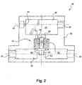
- the recirculating valve 26 includes a one-piece valve body 30 having a fuel supply passage 32.
- the fuel supply passage 32 has a fuel supply inlet port 34 receiving fuel from the fuel tank and a fuel supply outlet port 36 directing fuel to the engine.
- Body 30 further includes a fuel return passage 38 with a fuel return inlet port 40 receiving excess fuel from engine 18, and a fuel return outlet port 42 fluidly connected to fuel tank 12.
- Fuel return passage 38 includes an enlarged air separation chamber, indicated at 43, with ports 40 and 42 connected toward the upper portion of the chamber.
- a restricted orifice 44 is provided between the chamber 43 and the fuel return outlet port 42.
- a valve passage 48 interconnects chamber 43 and fuel supply passage 32.
- Valve passage 48 includes a reduced diameter portion 49 opening into the lower portion of chamber 43, and a enlarged diameter portion 50 opening into fuel supply passage 32.
- An annular shoulder 51 is defined between reduced portion 49 and enlarged portion 50.
- the recirculation valve 26 includes a pressure valve, indicated generally at 54.
- the pressure valve 54 controls the recirculation of excess heated fuel received through fuel return inlet port 40 to the fuel supply passage 32.
- the pressure valve 54 includes a hollow valve head 56 having an annular elastomeric gasket 58 mounted thereon. Gasket 58 is closely received on a cylindrical body portion 59 of the valve head and retained between a lower annular flange 60 and an upper annular flange 62 at opposite ends of head.
- the pressure valve 54 further includes a hollow thermal valve body 66 having an outer annular lower spring stop portion 68 and an inner annular lower spring stop portion 70.
- Body 66 further includes a central cylindrical post 72 projecting axially upward from inner annular lower spring stop portion 70.
- valve head 56 and thermal valve body 66 are each preferably formed in one piece from an appropriate material, such as plastic.
- a pressure regulator spring 74 is received about the central post 72 of body 66, and extends between the lower spring stop 70 and the lower annular flange 60 of valve head 56 (see Fig. 2).
- a thermal actuator return spring 76 is also received about central post 72 and extends between outer spring stop 68 and shoulder 51 in valve passage 49 (see Fig. 2).
- the pressure valve further includes a thermal actuator 80 that is received within the hollow thermal valve body 66.
- Thermal actuator 80 includes a cylindrical base 81 which is fixed to a cylindrical flange 83 (Fig. 2) projecting from valve body 30 into fuel supply passage 32.
- An annular flange 84 surrounds base 81 and allows the actuator to be properly located in a small cylindrical chamber of thermal valve body 66.
- the thermal actuator 80 further includes a central post 85 which is normally retracted within a cylindrical body 86 in the actuator when the ambient temperature exposed to base 81 is below a predetermined level, but which extends outwardly from body 86 when the ambient temperature exposed to base 81 increases above such predetermined level.
- the operation of the thermal actuator 80 should be well-known to those skilled in the art.
- Thermal actuator 80 is preferably a commercially-available actuator from Caltherm, under Part No. CT 5032-02M. Thermal actuators of this type are commonly used in automotive coolant thermostats. It is noted that other types of thermal actuators could also be used with the present invention, one such alternative being a bi-metal, dome-shaped disk which would "flip" from one condition to another depending upon the temperature to which it is exposed. Other such appropriate actuators should also be well-known to those skilled in the art.
- the thermal actuator 80 fits closely within thermal valve body 66, and the cylindrical post 72 of the thermal valve body 66 is received closely within the hollow cylindrical body 59 of the valve head 66.
- thermal actuator return spring 76 biases thermal valve body 66 downwardly, away from shoulder 51, such that the body 66 is maintained in an even, non-cocked position.
- the pressure regulator spring 74 biases valve head 56 upwardly, toward shoulder 51, such that gasket 58 is sealed against the shoulder. Shoulder 51 thereby also provides a valve seat for the pressure valve 54.
- FIG. 2 illustrates the cold start or cold operating condition of the engine, where the ambient temperature and fuel are at relatively low temperatures.
- Fuel is drawn from the fuel tank, and directed through fuel supply passage 32 to the filter, and then on to the engine.
- the base 81 of the thermal actuator 80 is exposed to the fuel, and the thermal actuator is maintained in a non-operative, or retracted condition.
- excess air typically at pressures of less than 2 psi (103 mm Hg)
- the pressure valve 54 is set through the spring constant of pressure regulator spring 74, such that the pressure regulator valve remains closed.
- the air passes through the restricted orifice 54 and through fuel return outlet port 40 directly back to the fuel tank.
- the pressure valve 54 prevents the air from being recirculated to the engine, and thereby maintains the efficiency of the engine.
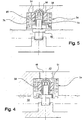
- the thermal actuator valve 80 becomes operational, with post 85 extending outwardly from body 86, as illustrated in Figure 5.
- Post 85 forces cylindrical post 72, and hence thermal valve body 66, upwardly within valve passage 49. This action compresses thermal actuator return spring 76, and causes additional upward force on valve head 56 through pressure regulator spring 74 to cause seal 58 to seal against shoulder 51 of valve passage 49.
- the air and excess fuel are thereby both directed back to the tank through orifice 44.
- Air separation chamber 43 is sized so as to collect excess fuel and allow the fuel to recirculate through pressure valve 44, and to allow any returning air to pass through restricted orifice 44 and return directly to the fuel tank.
- the size of the air separation chamber, the size of the restricted orifice 44, and the spring force on pressure regulator spring 74, can be easily determined depending upon the particular application.
- a device for controlling the recirculation of fuel in the fuel system of an internal combustion engine.
- the device effectively separates air from the excess fuel, such that the excess fuel can be used to heat the filter and prevent waxing and plugging during cold-start operation, while any air is directed back to the fuel tank such that it will not reduce the efficiency of the engine.
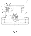
- a relief valve can alternatively be provided to accomplish the same result as the fixed orifice 44, as well as to reduce the pressure drop of excess fuel returning to the tank during warm operation.
- the relief valve 90 includes an annular elastomeric seal 92 with a central restricted orifice 93.
- a relief spring 96 normally urges seal 92 against an annular flange 97 surrounding an opening 98 into chamber 43.
- Relief spring 96 preferably has a spring force slightly greater than pressure regulator spring 74, such that the relief valve remains closed when the pressure valve is operational.
- the spring force of relief spring 96 can also easily be determined depending upon the particular application.
- the other operating characteristics of the pressure relief valve shown in Figure 6 are the same as described previously with respect to Figures 2-5.
Abstract
Description
Claims (10)
- A recirculation valve (26) for controlling the recirculation of fuel from a fuel tank (12) to an engine (18) where air is also supplied from the engine (18), the recirculation valve (26) having a valve body (30) having a fuel supply inlet port (34) to receive fuel from the tank (12), a fuel supply outlet port (36) to direct fuel to the engine (18), a fuel return inlet port (40) to receive excess fuel and air from the engine (18), and a fuel return outlet port (42) fluidly connected to the tank (12), a fuel supply passage (32) interconnecting the fuel supply inlet port (34) and the fuel supply outlet port (36), and a fuel return passage (38) interconnecting the fuel return inlet port (40) and the fuel return outlet port (42); characterized in that the recirculation valve includes
a pressure valve (54) located in a valve passage (48) between the fuel supply passage (32) and the fuel return passage (38), the pressure valve (54) normally in a closed condition when fuel is absent in the fuel return passage (38), and moving to an open condition in response to fuel pressure in the fuel return passage (38) to allow fuel in the fuel return passage (38) to flow to the fuel supply passage (32), the pressure valve (54) preventing air in the fuel return passage (38) from communicating with fuel in the fuel supply passage (32), and a thermal actuator (80) responsive to fuel temperature in the fuel supply passage (32), the thermal actuator (80) maintaining the pressure valve (54) in the closed condition when the fuel temperature in the fuel supply passage is above a predetermined level. - The recirculation valve (26) as in claim 1, wherein said pressure valve includes a valve seal (58) biased by a first spring (74) into sealed relation against a valve seat (51) in the valve passage (48) when the pressure valve (54) is in the closed condition, and moveable away from the valve seat (51) when the pressure valve (54) is in the open condition.
- The recirculation valve (26) as in either of the previous claims, wherein the thermal actuator (80) operatively engages the pressure valve (54) to maintain the pressure valve in the closed condition when the fuel temperature in the fuel supply passage (32) is above a predetermined level.
- The recirculation valve (26) as in claim 3, further including a thermal valve body (66) receiving the thermal actuator (80), the thermal valve body (66) having an annular lower spring stop (68), and the first spring (74) for the pressure valve extending between the valve seal (58) and the lower spring stop (68) of the thermal valve body (66), the thermal actuator (80) moving the thermal valve body (66), and hence the lower spring stop (68), toward the valve seal (58) when the fuel temperature is above the predetermined level so as to urge the pressure valve (54) into the closed condition, and further including an additional spring (76) extending between the valve seat (51) in the valve passage (48) and the lower spring stop (68) of the thermal valve body (66), the additional spring (76) urging the thermal valve body (66) away from the valve seal (58).
- The recirculation valve (26) as in claim 4, wherein the pressure valve (34) includes a valve head (56) which has a hollow cylindrical body (59), and the thermal valve body (66) also includes a cylindrical body (72) extending internally of the hollow cylindrical body (72) of the valve head (56).
- The recirculation valve (26) as in claim 5, wherein the valve seal (58) has an annular configuration closely surrounding the valve head (56), the valve head (56) having a pair of outwardly-projecting flanges (60, 62) retaining the valve seal (58) on the valve head (56), a lower of the flanges (60) providing the upper spring stop for the first spring (74).
- The recirculation valve (26) as in any of the previous claims, wherein the valve body further includes an air separation chamber (43) in the fuel return passage (38), the air separation chamber (43) having a dimension such that fuel collects in a lower portion of the chamber (43) and air collects in an upper portion of the chamber (43).
- The recirculation valve (26) as in claim 7, wherein the valve body (30) further includes a restrictive orifice (44) between the air separation chamber (43) and the fuel return outlet port (42), the restrictive orifice (44) causing an increase in pressure in the chamber (43) when fuel enters the air separation chamber (43).
- The recirculation valve (26) as in either of claims 7 or 8, wherein the fuel return inlet port (40) and fuel return outlet port (42) open into the upper portion of the chamber (43).
- The recirculation valve (26) as in any of the previous claims, further including a relief valve (90) in the fuel return outlet port (42).
Applications Claiming Priority (6)
| Application Number | Priority Date | Filing Date | Title |
|---|---|---|---|
| US16747499P | 1999-11-24 | 1999-11-24 | |
| US164474P | 1999-11-24 | ||
| US167474P | 1999-11-24 | ||
| US477489 | 2000-01-04 | ||
| US09/477,489 US6289879B1 (en) | 1999-11-24 | 2000-01-04 | Air eliminating return fuel recirculation valve |
| PCT/US2000/028787 WO2001038718A1 (en) | 1999-11-24 | 2000-10-18 | Air eliminating return fuel recirculation valve |
Publications (2)
| Publication Number | Publication Date |
|---|---|
| EP1234111A1 EP1234111A1 (en) | 2002-08-28 |
| EP1234111B1 true EP1234111B1 (en) | 2005-06-08 |
Family
ID=56289986
Family Applications (1)
| Application Number | Title | Priority Date | Filing Date |
|---|---|---|---|
| EP00972255A Expired - Lifetime EP1234111B1 (en) | 1999-11-24 | 2000-10-18 | Air eliminating return fuel recirculation valve |
Country Status (6)
| Country | Link |
|---|---|
| US (1) | US6289879B1 (en) |
| EP (1) | EP1234111B1 (en) |
| AT (1) | ATE297502T1 (en) |
| BR (1) | BR0015720A (en) |
| DE (1) | DE60020731T2 (en) |
| ES (1) | ES2240188T3 (en) |
Families Citing this family (24)
| Publication number | Priority date | Publication date | Assignee | Title |
|---|---|---|---|---|
| US6527947B1 (en) | 2000-09-18 | 2003-03-04 | Ford Global Technologies, Inc. | Fuel control device |
| DE10059012A1 (en) * | 2000-11-28 | 2002-06-13 | Bosch Gmbh Robert | Fuel injection system with fuel preheating and fuel-cooled pressure control valve |
| SE520676C2 (en) * | 2001-12-11 | 2003-08-12 | Volvo Lastvagnar Ab | Device for fuel systems for an internal combustion engine |
| DE10314223A1 (en) * | 2003-03-28 | 2004-10-21 | Siemens Ag | Conveyor |
| US6981491B2 (en) * | 2004-01-30 | 2006-01-03 | Siemens Vdo Automotive Corporation | Coupling valve structure for fuel supply module |
| DE102004050601B4 (en) * | 2004-10-15 | 2006-12-21 | Kangler, Wolfram, Dipl.-Phys. | The heat exchange module |
| US20060137663A1 (en) * | 2004-12-29 | 2006-06-29 | Shawn Vaught | Apparatus for separating entrained air from a liquid |
| JP4347271B2 (en) * | 2005-07-06 | 2009-10-21 | 京三電機株式会社 | Return recirculation valve |
| JP2007285235A (en) * | 2006-04-18 | 2007-11-01 | Honda Motor Co Ltd | Fuel supply device for diesel engine |
| US7779818B2 (en) * | 2007-07-12 | 2010-08-24 | Caterpillar Inc. | System and method for priming a fluid system |
| US8327827B2 (en) * | 2007-10-31 | 2012-12-11 | Brp Us Inc. | Fuel-injected engine and method of assembly thereof |
| KR100999624B1 (en) * | 2008-09-04 | 2010-12-08 | 현대자동차주식회사 | High-pressure fuel supply circuit |
| US8186332B2 (en) * | 2009-07-20 | 2012-05-29 | Mann & Hummel Gmbh | Fluid filter with integrated temperature regulation |
| US9776507B2 (en) * | 2010-12-14 | 2017-10-03 | GM Global Technology Operations LLC | Temperature based fuel management in a vehicle fuel system |
| US9316187B2 (en) * | 2011-01-18 | 2016-04-19 | Carter Fuel Systems, Llc | Diesel fuel system with advanced priming |
| EP2650526B1 (en) * | 2012-03-14 | 2017-02-15 | Kubota Corporation | Device for supplying fuel to engine |
| CN104471233B (en) | 2012-06-27 | 2017-03-08 | 康明斯过滤Ip公司 | Hot recycle valve for fuel filter module |
| SE537126C2 (en) * | 2013-05-30 | 2015-02-03 | Scania Cv Ab | Fuel |
| US20160186706A1 (en) * | 2014-07-15 | 2016-06-30 | Brazil Green Energy Technologies, Llc | Systems and methods for fuel state control with fuel recirculation and preheat |
| US9790904B2 (en) * | 2014-11-14 | 2017-10-17 | Hyundai Motor Company | Diesel fuel recirculation device |
| WO2017151800A1 (en) | 2016-03-01 | 2017-09-08 | CT Energy Holdings, LLC | Fuel heating apparatus and methods |
| DE102017007603A1 (en) | 2017-08-11 | 2019-02-14 | Hydac Fluidcarecenter Gmbh | Delivery device for the fuel of a combustion engine |
| DE102017011050A1 (en) | 2017-11-29 | 2019-05-29 | Daimler Ag | Valve device and fuel filter module |
| DE102018212640A1 (en) * | 2018-07-30 | 2020-01-30 | Bayerische Motoren Werke Aktiengesellschaft | Device and method for removing fuel vapor from a fuel supply system for an internal combustion engine |
Family Cites Families (25)
| Publication number | Priority date | Publication date | Assignee | Title |
|---|---|---|---|---|
| US2222274A (en) * | 1938-11-19 | 1940-11-19 | John Deere Tractor Co | Fuel system for internal combustion engines |
| US2599699A (en) * | 1947-05-13 | 1952-06-10 | Gen Motors Corp | Fuel system for combustion apparatus |
| US2729339A (en) | 1953-08-28 | 1956-01-03 | Purolator Products Inc | Automatic discriminatory clogging detector for oil filters |
| US2942572A (en) | 1958-06-17 | 1960-06-28 | Pall Corp | Magnetic pressure indicator |
| US3754538A (en) | 1971-11-02 | 1973-08-28 | Gen Motors Corp | Engine crankcase ventilation |
| US3836074A (en) | 1972-08-30 | 1974-09-17 | Pneumo Dynamics Corp | Bi-thermal bleed valve |
| US4172971A (en) | 1978-10-30 | 1979-10-30 | Pall Corporation | Magnetic pressure indicator with thermal lockout |
| US4452213A (en) * | 1979-07-13 | 1984-06-05 | Duprez Wayne R | Diesel fuel control valve and system |
| US4502450A (en) | 1979-07-13 | 1985-03-05 | Standard-Thomson Corporation | Diesel fuel control valve and system |
| US4379053A (en) | 1981-06-12 | 1983-04-05 | Brane Earl P | Filter bypass valve assembly |
| US4502451A (en) | 1982-08-25 | 1985-03-05 | Standard-Thomson Corporation | Diesel fuel control apparatus and system |
| US4503885A (en) * | 1983-12-16 | 1985-03-12 | Chrysler Corporation | Engine fuel supply system |
| US4543938A (en) * | 1984-02-02 | 1985-10-01 | Stant Inc. | In-line fuel reservoir |
| JPS60143122U (en) | 1984-03-05 | 1985-09-21 | アイシン精機株式会社 | oil separator |
| GB8406270D0 (en) * | 1984-03-09 | 1984-04-11 | Lucas Ind Plc | Fuel system |
| US4617116A (en) * | 1984-05-04 | 1986-10-14 | Ford Motor Company | Automotive type fuel feed system |
| US4554848A (en) * | 1984-08-27 | 1985-11-26 | Galletto Joseph L | Internal pliers |
| DE3710807A1 (en) * | 1987-03-31 | 1988-10-13 | Daimler Benz Ag | LOW-PRESSURE FUEL CIRCUIT WITH FUEL PREHEATING FOR AN AIR COMPRESSING INJECTION COMBUSTION ENGINE |
| DE3713210A1 (en) | 1987-04-18 | 1988-11-03 | Porsche Ag | VENTILATION DEVICE WITH INTEGRATED OIL SEPARATOR |
| US4886019A (en) | 1988-11-14 | 1989-12-12 | Arrow Specialty Company | Engine breather assembly with oil drain back |
| US5318268A (en) | 1993-06-10 | 1994-06-07 | Eaton Corporation | Thermally actuated valve with ambient temperature compensation |
| DE19602082B4 (en) * | 1996-01-20 | 2004-04-08 | Mann + Hummel Gmbh | Fuel module |
| FR2751242B1 (en) | 1996-07-18 | 1998-09-25 | Filtrauto | DIESEL ENGINE FILTER AND FUEL DEVICE INCLUDING SUCH A FILTER |
| US5832902A (en) * | 1997-05-15 | 1998-11-10 | Davco Manufacturing L.L.C. | Fuel temperature control bypass circuit |
| US5887573A (en) | 1997-06-25 | 1999-03-30 | Stanadyne Automotive Corp. | Fuel filter with cold start circuit |
-
2000
- 2000-01-04 US US09/477,489 patent/US6289879B1/en not_active Expired - Lifetime
- 2000-10-18 DE DE60020731T patent/DE60020731T2/en not_active Expired - Lifetime
- 2000-10-18 AT AT00972255T patent/ATE297502T1/en not_active IP Right Cessation
- 2000-10-18 BR BR0015720-1A patent/BR0015720A/en not_active IP Right Cessation
- 2000-10-18 ES ES00972255T patent/ES2240188T3/en not_active Expired - Lifetime
- 2000-10-18 EP EP00972255A patent/EP1234111B1/en not_active Expired - Lifetime
Also Published As
| Publication number | Publication date |
|---|---|
| BR0015720A (en) | 2002-07-09 |
| ES2240188T3 (en) | 2005-10-16 |
| ATE297502T1 (en) | 2005-06-15 |
| DE60020731D1 (en) | 2005-07-14 |
| US6289879B1 (en) | 2001-09-18 |
| DE60020731T2 (en) | 2006-05-04 |
| EP1234111A1 (en) | 2002-08-28 |
Similar Documents
| Publication | Publication Date | Title |
|---|---|---|
| EP1234111B1 (en) | Air eliminating return fuel recirculation valve | |
| US4187813A (en) | Fuel supply device | |
| US5979778A (en) | Thermostatic valve arrangement | |
| US5509390A (en) | Temperature-responsive demand fuel pressure regulator | |
| US6527947B1 (en) | Fuel control device | |
| EP0638713B1 (en) | Temperature control system for an internal combustion engine | |
| JPS60164657A (en) | Fuel filter device for diesel engine | |
| WO2001083961A1 (en) | Thermostat device | |
| US6761321B2 (en) | Thermostat device | |
| GB2280729A (en) | Thermostatic mixing valve | |
| CA2386935C (en) | Air eliminating return fuel recirculation valve | |
| EP0754853B1 (en) | Fuel supply system | |
| JPS5818549A (en) | Fuel feeder for internal combustion engine | |
| US4703738A (en) | Purge flow control valve | |
| US5787845A (en) | Combined bypass and thermostat assembly | |
| US6244294B1 (en) | Radiator pressure release valve for a temperature control system | |
| JP2539156Y2 (en) | Vaporizer heating device | |
| JP2580298Y2 (en) | Thermostat device for internal combustion engine | |
| JPS6229645Y2 (en) | ||
| EP0137733B1 (en) | Air temperature control device for the intake air of an engine | |
| JPS6145067B2 (en) | ||
| WO2003025382A1 (en) | Heat exchanger for pre-heating liquid fuel with engine coolant fluid | |
| JPS62186054A (en) | Fuel filter for diesel engine | |
| JPS61167155A (en) | Pressure regulator for internal-combustion engine | |
| JPH02191860A (en) | Fuel filter device for diesel engine |
Legal Events
| Date | Code | Title | Description |
|---|---|---|---|
| PUAI | Public reference made under article 153(3) epc to a published international application that has entered the european phase |
Free format text: ORIGINAL CODE: 0009012 |
|
| 17P | Request for examination filed |
Effective date: 20020531 |
|
| AK | Designated contracting states |
Kind code of ref document: A1 Designated state(s): AT BE CH CY DE DK ES FI FR GB GR IE IT LI LU MC NL PT SE |
|
| GRAP | Despatch of communication of intention to grant a patent |
Free format text: ORIGINAL CODE: EPIDOSNIGR1 |
|
| GRAS | Grant fee paid |
Free format text: ORIGINAL CODE: EPIDOSNIGR3 |
|
| GRAA | (expected) grant |
Free format text: ORIGINAL CODE: 0009210 |
|
| AK | Designated contracting states |
Kind code of ref document: B1 Designated state(s): AT BE CH CY DE DK ES FI FR GB GR IE IT LI LU MC NL PT SE |
|
| PG25 | Lapsed in a contracting state [announced via postgrant information from national office to epo] |
Ref country code: NL Free format text: LAPSE BECAUSE OF FAILURE TO SUBMIT A TRANSLATION OF THE DESCRIPTION OR TO PAY THE FEE WITHIN THE PRESCRIBED TIME-LIMIT Effective date: 20050608 Ref country code: LI Free format text: LAPSE BECAUSE OF FAILURE TO SUBMIT A TRANSLATION OF THE DESCRIPTION OR TO PAY THE FEE WITHIN THE PRESCRIBED TIME-LIMIT Effective date: 20050608 Ref country code: FI Free format text: LAPSE BECAUSE OF FAILURE TO SUBMIT A TRANSLATION OF THE DESCRIPTION OR TO PAY THE FEE WITHIN THE PRESCRIBED TIME-LIMIT Effective date: 20050608 Ref country code: AT Free format text: LAPSE BECAUSE OF FAILURE TO SUBMIT A TRANSLATION OF THE DESCRIPTION OR TO PAY THE FEE WITHIN THE PRESCRIBED TIME-LIMIT Effective date: 20050608 Ref country code: BE Free format text: LAPSE BECAUSE OF FAILURE TO SUBMIT A TRANSLATION OF THE DESCRIPTION OR TO PAY THE FEE WITHIN THE PRESCRIBED TIME-LIMIT Effective date: 20050608 Ref country code: CH Free format text: LAPSE BECAUSE OF FAILURE TO SUBMIT A TRANSLATION OF THE DESCRIPTION OR TO PAY THE FEE WITHIN THE PRESCRIBED TIME-LIMIT Effective date: 20050608 |
|
| REG | Reference to a national code |
Ref country code: GB Ref legal event code: FG4D |
|
| REG | Reference to a national code |
Ref country code: CH Ref legal event code: EP |
|
| REF | Corresponds to: |
Ref document number: 60020731 Country of ref document: DE Date of ref document: 20050714 Kind code of ref document: P |
|
| REG | Reference to a national code |
Ref country code: IE Ref legal event code: FG4D |
|
| REG | Reference to a national code |
Ref country code: SE Ref legal event code: TRGR |
|
| PG25 | Lapsed in a contracting state [announced via postgrant information from national office to epo] |
Ref country code: DK Free format text: LAPSE BECAUSE OF FAILURE TO SUBMIT A TRANSLATION OF THE DESCRIPTION OR TO PAY THE FEE WITHIN THE PRESCRIBED TIME-LIMIT Effective date: 20050908 Ref country code: GR Free format text: LAPSE BECAUSE OF FAILURE TO SUBMIT A TRANSLATION OF THE DESCRIPTION OR TO PAY THE FEE WITHIN THE PRESCRIBED TIME-LIMIT Effective date: 20050908 |
|
| REG | Reference to a national code |
Ref country code: ES Ref legal event code: FG2A Ref document number: 2240188 Country of ref document: ES Kind code of ref document: T3 |
|
| PG25 | Lapsed in a contracting state [announced via postgrant information from national office to epo] |
Ref country code: CY Free format text: LAPSE BECAUSE OF FAILURE TO SUBMIT A TRANSLATION OF THE DESCRIPTION OR TO PAY THE FEE WITHIN THE PRESCRIBED TIME-LIMIT Effective date: 20051018 Ref country code: IE Free format text: LAPSE BECAUSE OF NON-PAYMENT OF DUE FEES Effective date: 20051018 |
|
| PG25 | Lapsed in a contracting state [announced via postgrant information from national office to epo] |
Ref country code: LU Free format text: LAPSE BECAUSE OF NON-PAYMENT OF DUE FEES Effective date: 20051031 Ref country code: MC Free format text: LAPSE BECAUSE OF NON-PAYMENT OF DUE FEES Effective date: 20051031 |
|
| PG25 | Lapsed in a contracting state [announced via postgrant information from national office to epo] |
Ref country code: PT Free format text: LAPSE BECAUSE OF FAILURE TO SUBMIT A TRANSLATION OF THE DESCRIPTION OR TO PAY THE FEE WITHIN THE PRESCRIBED TIME-LIMIT Effective date: 20051114 |
|
| NLV1 | Nl: lapsed or annulled due to failure to fulfill the requirements of art. 29p and 29m of the patents act | ||
| REG | Reference to a national code |
Ref country code: CH Ref legal event code: PL |
|
| ET | Fr: translation filed | ||
| PLBE | No opposition filed within time limit |
Free format text: ORIGINAL CODE: 0009261 |
|
| STAA | Information on the status of an ep patent application or granted ep patent |
Free format text: STATUS: NO OPPOSITION FILED WITHIN TIME LIMIT |
|
| 26N | No opposition filed |
Effective date: 20060309 |
|
| REG | Reference to a national code |
Ref country code: IE Ref legal event code: MM4A |
|
| REG | Reference to a national code |
Ref country code: FR Ref legal event code: PLFP Year of fee payment: 16 |
|
| REG | Reference to a national code |
Ref country code: FR Ref legal event code: PLFP Year of fee payment: 17 |
|
| REG | Reference to a national code |
Ref country code: FR Ref legal event code: PLFP Year of fee payment: 18 |
|
| REG | Reference to a national code |
Ref country code: FR Ref legal event code: PLFP Year of fee payment: 19 |
|
| PGFP | Annual fee paid to national office [announced via postgrant information from national office to epo] |
Ref country code: SE Payment date: 20191029 Year of fee payment: 20 Ref country code: DE Payment date: 20191029 Year of fee payment: 20 |
|
| PGFP | Annual fee paid to national office [announced via postgrant information from national office to epo] |
Ref country code: IT Payment date: 20191023 Year of fee payment: 20 Ref country code: FR Payment date: 20191025 Year of fee payment: 20 Ref country code: ES Payment date: 20191104 Year of fee payment: 20 |
|
| PGFP | Annual fee paid to national office [announced via postgrant information from national office to epo] |
Ref country code: GB Payment date: 20191028 Year of fee payment: 20 |
|
| REG | Reference to a national code |
Ref country code: DE Ref legal event code: R071 Ref document number: 60020731 Country of ref document: DE |
|
| REG | Reference to a national code |
Ref country code: GB Ref legal event code: PE20 Expiry date: 20201017 |
|
| PG25 | Lapsed in a contracting state [announced via postgrant information from national office to epo] |
Ref country code: GB Free format text: LAPSE BECAUSE OF EXPIRATION OF PROTECTION Effective date: 20201017 |
|
| REG | Reference to a national code |
Ref country code: ES Ref legal event code: FD2A Effective date: 20210129 |
|
| PG25 | Lapsed in a contracting state [announced via postgrant information from national office to epo] |
Ref country code: ES Free format text: LAPSE BECAUSE OF EXPIRATION OF PROTECTION Effective date: 20201019 |