EP1233308A2 - Image forming apparatus - Google Patents
Image forming apparatus Download PDFInfo
- Publication number
- EP1233308A2 EP1233308A2 EP02003654A EP02003654A EP1233308A2 EP 1233308 A2 EP1233308 A2 EP 1233308A2 EP 02003654 A EP02003654 A EP 02003654A EP 02003654 A EP02003654 A EP 02003654A EP 1233308 A2 EP1233308 A2 EP 1233308A2
- Authority
- EP
- European Patent Office
- Prior art keywords
- image
- recording material
- image forming
- electrification
- forming apparatus
- Prior art date
- Legal status (The legal status is an assumption and is not a legal conclusion. Google has not performed a legal analysis and makes no representation as to the accuracy of the status listed.)
- Withdrawn
Links
Images


Classifications
-
- G—PHYSICS
- G03—PHOTOGRAPHY; CINEMATOGRAPHY; ANALOGOUS TECHNIQUES USING WAVES OTHER THAN OPTICAL WAVES; ELECTROGRAPHY; HOLOGRAPHY
- G03G—ELECTROGRAPHY; ELECTROPHOTOGRAPHY; MAGNETOGRAPHY
- G03G15/00—Apparatus for electrographic processes using a charge pattern
- G03G15/02—Apparatus for electrographic processes using a charge pattern for laying down a uniform charge, e.g. for sensitising; Corona discharge devices
- G03G15/0208—Apparatus for electrographic processes using a charge pattern for laying down a uniform charge, e.g. for sensitising; Corona discharge devices by contact, friction or induction, e.g. liquid charging apparatus
- G03G15/0216—Apparatus for electrographic processes using a charge pattern for laying down a uniform charge, e.g. for sensitising; Corona discharge devices by contact, friction or induction, e.g. liquid charging apparatus by bringing a charging member into contact with the member to be charged, e.g. roller, brush chargers
-
- G—PHYSICS
- G03—PHOTOGRAPHY; CINEMATOGRAPHY; ANALOGOUS TECHNIQUES USING WAVES OTHER THAN OPTICAL WAVES; ELECTROGRAPHY; HOLOGRAPHY
- G03G—ELECTROGRAPHY; ELECTROPHOTOGRAPHY; MAGNETOGRAPHY
- G03G15/00—Apparatus for electrographic processes using a charge pattern
- G03G15/02—Apparatus for electrographic processes using a charge pattern for laying down a uniform charge, e.g. for sensitising; Corona discharge devices
- G03G15/0283—Arrangements for supplying power to the sensitising device
-
- G—PHYSICS
- G03—PHOTOGRAPHY; CINEMATOGRAPHY; ANALOGOUS TECHNIQUES USING WAVES OTHER THAN OPTICAL WAVES; ELECTROGRAPHY; HOLOGRAPHY
- G03G—ELECTROGRAPHY; ELECTROPHOTOGRAPHY; MAGNETOGRAPHY
- G03G2215/00—Apparatus for electrophotographic processes
- G03G2215/00362—Apparatus for electrophotographic processes relating to the copy medium handling
- G03G2215/00367—The feeding path segment where particular handling of the copy medium occurs, segments being adjacent and non-overlapping. Each segment is identified by the most downstream point in the segment, so that for instance the segment labelled "Fixing device" is referring to the path between the "Transfer device" and the "Fixing device"
- G03G2215/00409—Transfer device
-
- G—PHYSICS
- G03—PHOTOGRAPHY; CINEMATOGRAPHY; ANALOGOUS TECHNIQUES USING WAVES OTHER THAN OPTICAL WAVES; ELECTROGRAPHY; HOLOGRAPHY
- G03G—ELECTROGRAPHY; ELECTROPHOTOGRAPHY; MAGNETOGRAPHY
- G03G2215/00—Apparatus for electrophotographic processes
- G03G2215/00362—Apparatus for electrophotographic processes relating to the copy medium handling
- G03G2215/00535—Stable handling of copy medium
- G03G2215/00556—Control of copy medium feeding
- G03G2215/00599—Timing, synchronisation
Definitions
- the present invention relates to an image forming apparatus for forming an image by using an electrophotographic system or an electrostatic recording system, particularly to an image forming apparatus such as a copying machine, a printer or a facsimile.
- An image forming apparatus such as an electrophotographic apparatus (a copying machine, a laser printer or the like) or an electrostatic recording apparatus is known in which: an image forming process that includes a step of conducting electrification processing to an image bearing member is applied to an image bearing member such as an electrophotographic photosensitive member or an electrostatic recording dielectric of rotary drum type or endless belt type, to thereby form an electrostatic latent image corresponding to target image information; the electrostatic latent image is visualized (into a toner image) by a developer; the toner image is transferred to a recording material and further fixed to be output as an image formed material (copy, print); and the image bearing member is repeatedly used for image formation.
- an image forming process that includes a step of conducting electrification processing to an image bearing member is applied to an image bearing member such as an electrophotographic photosensitive member or an electrostatic recording dielectric of rotary drum type or endless belt type, to thereby form an electrostatic latent image corresponding to target image information
- the electrostatic latent image is visualized (
- a corona discharge device has been conventionally and widely used as a means for electrifying the image bearing member (hereinafter referred to as photosensitive member).
- the corona discharge apparatus is arranged so as to oppose the photosensitive member in a non-contact manner, and the surface of the photosensitive member is exposed to a corona shower emitted from the corona discharge apparatus to which a high voltage is applied, thereby making the photosensitive member surface undergo corona electrification.
- a contact type electrifying apparatus can attain a lower voltage of a power source in comparison with the corona discharge apparatus, and thus has advantages such as reduced amount of ozone generation. As a result, the contact type electrifying apparatus has been attracting attention and has been put to practical use.
- a roller type (electrifying roller), a blade type, a fur-brush type, or a magnetic brush type conductive electrifying member (contact electrifying means) is made to contact with a member to be electrified such as the image bearing member, and a predetermined bias voltage is applied to the electrifying member, thereby electrifying the member to be electrified with predetermined polarity and potential.
- a method in which a bias applied to the electrifying member is only a direct current voltage (DC application method) and a method in which a bias applied to the electrifying member is a voltage obtained by superimposing a direct current voltage on an alternating voltage (AC application method) are given.
- DC application method direct current voltage
- AC application method a method in which a bias applied to the electrifying member is a voltage obtained by superimposing a direct current voltage on an alternating voltage
- electrification of the photosensitive member requires to have been previously started before image formation. Specifically, unless electrification has been previously started and performed for at least a period for one peripheral length of the rotating photosensitive member, the electrification potential is unstable, and it is difficult to obtain a satisfactory image with uniform image density. Thus, in the case where a synchronizing means of a recording material is located close to an image forming part, the electrification is required to start at the position of a sensor in an upstream side of the image forming part or with a reference signal.
- a recording material is always caused to wait at the position of the synchronizing means. If the recording material is not caused to wait at the position for the synchronization, an excess time is required until image formation is completed after the preparation for image formation is completed,, whereby an unpleasant feeling is given to a user. That is, if feeding of the recording material is started after preparations for the image forming apparatus are completed, an excess time is needed from the start of image formation until the completion by that amount.
- time may be required for image data processing such as accumulation /expansion of memory.
- the present invention has been made in view of the above, and an object of the present invention is therefore to provide an image forming apparatus capable of reducing consumption of power necessary for electrification of an image bearing member as much as possible.
- Another object of the present invention is to provide an image forming apparatus capable of extending a life of the image bearing member.
- Fig. 1 is a schematic structural diagram showing an image forming apparatus in this embodiment.
- the image forming apparatus in this embodiment is a laser beam printer utilizing a transfer electrophotographic process, a contact electrification system, and a reversal developing system.
- Reference numeral 1 denotes a rotation drum type electrophotographic photosensitive member (hereinafter referred to as photosensitive member for short) as an image bearing member.
- the photosensitive member 1 is rotatively driven at a process speed (peripheral velocity) of 150 mm/sec in a clockwise direction indicated by an arrow a. Further, the photosensitive member including the surface layer 1a with a thickness at an initial stage of 30 ⁇ m is used.
- Reference numeral 2 denotes an electrifying roller as a contact electrifying member (contact electrifying means, primary electrifying apparatus).
- the electrifying roller 2 is a roller with a composite-layer structure which is constituted of a core bar 2a as the center, an elastic conductive layer 2b formed into a roller shape concentrically and integrally with a peripheral surface of the core bar 2a, and a resistance layer 2c further formed on a peripheral surface of the elastic conductive layer 2b.
- the elastic conductive layer 2b is a single layer or a composite layer formed of conductive rubber (EPDM or the like) of 10 4 ⁇ cm or less, for example.
- the resistance layer 2c is a single layer or a composite layer made of hydrin rubber or TORESIN (trade name, nylon resin, carbon dispersion) with 10 7 to 10 11 ⁇ cm and with a thickness of 100 ⁇ m or less.
- the resistance layer 2c plays a function of preventing a leak to the photosensitive member 1 and preventing bleeding of a plasticizer in the elastic conductive layer 2b.
- Both end portions of the core bar 2a of the electrifying roller 2 are rotatably borne on a bearing member (not shown), and the electrifying roller 2 is arranged in parallel with the drum type photosensitive member 1 and is allowed to pressure-contact with the photosensitive member 1 with a predetermined pressing force by a pressing means (not shown).
- the electrifying roller 2 rotates in a counterclockwise direction indicated by an arrow in association with the rotation drive of the photosensitive member 1.
- a contact nip portion n between the photosensitive member 1 and the electrifying roller 2 corresponds to an electrifying area position (hereinafter referred to as electrifying nip portion).
- Reference numeral 3 denotes an electrification bias application power source (power source for the electrifying member).
- a predetermined bias voltage is applied to the core bar 2a of the electrifying roller 2 from the power source 3.
- the peripheral surface of the rotary photosensitive member 1 is uniformly electrified with predetermined polarity and potential by the contact electrification system.
- an AC application method in which a bias voltage (AC + DC) obtained by superimposing a direct current voltage on an alternating voltage is applied to the electrifying roller 2.
- An AC current component is set so that the photosensitive member 1 and the electrifying roller 2 can attain uniformity of electrification in an initial state.
- control with a direct current voltage component: a constant voltage of -750 V and an alternating current component: frequency of 1800 Hz and a constant current of 1500 ⁇ A is conducted to the electrifying roller 2, thereby obtaining -730 V as a surface potential (electrification potential, dark portion potential (non-exposure portion)) of the photosensitive member 1.
- Image exposure 4 is performed to the electrified surface of the rotary photosensitive member 1 by an exposure means 5 in accordance with input image data input to the image forming apparatus, whereby an electrostatic latent image corresponding to the image information is formed.
- the exposure means 5 is a laser beam scanning exposure means, a slit exposure means of an original image, or the like. In this embodiment, the laser beam scanning exposure means is used.
- a developer is applied to the surface of the rotary photosensitive member 1, on which the electrostatic latent image is formed by a developing apparatus 6, and thus, the electrostatic latent image is developed as a toner image.
- minus toner negative toner
- the electrostatic latent image is reversely developed.
- the developing apparatus 6 in this embodiment is an apparatus of jumping developing system using one-component magnetic toner.
- Reference numeral 6a denotes a non-magnetic developing sleeve, which is arranged so as to oppose the photosensitive member 1 through a gap of 0.3 mm and is rotatively driven in a counterclockwise direction indicated by an arrow.
- Reference numeral 6b denotes a non-rotary magnet roller insertingly arranged in the developing sleeve 6a.
- Toner t received in the developing apparatus is applied onto a peripheral surface of the developing sleeve 6a along with the rotation to thereby form a thin layer, and is held by a magnetic force of the magnet roller 6b to be carried to a developing part 6c where the photosensitive member 1 and the developing sleeve 6a oppose each other.
- a developing bias voltage a superimposed voltage: DC component -500 V AC component frequency of 1800 Hz, Vpp (peak to peak) of 1400 V is applied to the developing sleeve 6a from a developing bias application power source 8 (power source for a developing member).
- the toner flies at the developing part 6c, and the electrostatic latent image formed on the surface of the rotary photosensitive member 1 undergoes jumping developing.
- Reference numeral 7 denotes a transferring roller as a transfer means.
- the transferring roller 7 is constituted of a core bar (mandrel) 7a at the center and a middle-resistance elastic layer 7b formed into a roller shape concentrically and integrally with a peripheral surface of the core bar 7a.
- the transferring roller 7 in this embodiment is a conductive rubber roller with resistance of 5 ⁇ 10 8 ⁇ and a diameter of 16 mm.
- Both end portions of the core bar 7a of the transferring roller 7 are rotatably borne on a bearing member (not shown), and the transferring roller 7 is arranged in parallel with the drum type photosensitive member 1 and is allowed to pressure-contact with the photosensitive member 1 with a predetermined pressing force applied by a pressing means (not shown).
- the transferring roller 7 rotates in a counterclockwise direction indicated by an arrow in association with the rotation drive of the photosensitive member 1.
- a contact nip portion 7c between the photosensitive member 1 and the transferring roller 7 corresponds to a transfer area position (hereinafter referred to as transfer nip portion).
- the recording material P is fed from a sheet feeding portion 200 as a recording material receiving portion.
- the fed recording material P is caused to wait for a certain period of time by a pair of rollers for synchronizing (registration rollers) 50 as a synchronizing means (conveying means), and starts to be fed to the transfer nip portion 7c at certain timing. That is, the recording material P starts to be fed to the transfer nip portion 7c at timing such that, when a tip end portion of the toner image formed on the surface of the rotary photosensitive member 1 reaches the transfer nip portion 7c, a tip end portion of the recording material P also reaches the transfer nip portion 7c at exactly the same time.
- the surface of the recording material P fed to the transfer nip portion 7c adheres to the rotary photosensitive member 1, and the recording material P is sandwiched at and conveyed through the transfer nip portion. Further, from the time when the tip end portion of the recording material P reaches the transfer nip portion 7c until a rear end portion thereof passes through the transfer nip portion 7c, a predetermined direct current bias with a polarity opposite to that of the toner is applied as a transfer bias to the core bar 7a of the transferring roller 7 from a transfer bias application power source (power source for a transferring member). A DC voltage of +3500 V is applied in this embodiment.
- the toner image on the rotary photosensitive member 1 side is sequentially transferred onto the recording material P due to the action of a transfer electric field formed by the transferring roller 7 and a pressing force applied to the transfer nip portion 7c.
- the recording material P which has passed through the transfer nip portion 7c and has been separated from the surface of the rotary photosensitive member 1 is conveyed to a fixing apparatus 300, and is fixed with a toner image. Then, the recording material P is discharged to the outside of the apparatus main body. Alternatively, for example, if an image is to be formed also on the back surface, the recording material P is conveyed to a re-conveying means (not shown) to the transfer nip portion.
- the surface of the rotary photosensitive member 1 after the recording material separation is cleaned by being removed of residual attaching contaminant such as paper powder or toner remaining on the surface of the photosensitive member 1 without being transferred to the recording material P (transfer residual toner) by a cleaning blade 9a of a cleaning apparatus 9. Further, the surface is subjected to full exposure (pre-exposure) by a charge-removal device (charge-removal lamp) 11 to undergo erasing of electric memory to be initialized. Thus, the surface of the photosensitive member 1 can be repeatedly used for image formation.
- each of the rollers may be attached with a gear or the like and may be forcedly driven by a drive means such as a motor.
- Reference numeral 100 denotes a control circuit portion (control means) of the image forming apparatus.
- the image forming apparatus is sequence-controlled by the control circuit portion 100 in a predetermined manner.
- Reference numeral 101 denotes a drive portion of the pair of rollers for synchronizing 50, which is constituted of a clutch/motor and the like.
- the drive portion 101 is controlled by the control circuit portion 100, whereby the drive of the pair of rollers for synchronizing 50 is on/off-controlled at predetermined timing (on: rotation (sheet feeding), off: rotation stop (waiting for sheet feeding). That is, the control circuit portion 100 controls start timing for feeding the recording material P caused to wait at the pair of rollers 50.
- electrification is performed for a period for one peripheral length of the photosensitive member prior to image formation (before formation of an electrostatic latent image by image exposure) taking into consideration uniformity of the electrification potential of the photosensitive member surface. Further, it is not essential but is desirable that electrification for a period for one peripheral length of the photosensitive member is conducted also after the completion of image formation in order to conduct transfer or reduce exposure memory.
- the structure, or sequence is adopted in which image formation may be performed for 30 sheets of A4 traverse per minute.
- the distance between recording materials that is, sheet interval in continuous image formation for a plurality of recording materials is controlled at 90 mm (0.6 sec).
- a pair of follower rollers 51 are arranged at the position at a distance of 40 mm along the recording material conveying path from the transfer nip portion 7c between the transfer nip portion 7c and the pair of rollers for synchronizing 50.
- a sensor for detecting passage timing of the tip end of the recording material P is arranged at the position of the pair of follower rollers 51, and image exposure is started by instruction from the control circuit portion 100 on the basis of the sensor output.
- an angle ⁇ formed by the electrifying nip portion n and the transfer nip portion 7c in the photosensitive member rotational direction is 180° (Fig. 1).
- the electrification potential of the photosensitive member 1 after electrification has been performed for the period for one peripheral length is stable at -730 V. If image formation (exposure, developing, transfer and the like) is started at this point, the time required for discharging the recording material P on which the image is formed to the outside of the apparatus after input of an image forming start signal can be shortened as much as possible. Also, a satisfactory image with no fog and the like can be provided.
- the sequence such that electrification is started after about 50 msec from the time when the pair of rollers for synchronizing 50 are turned ON (driven) in this structure first, image formation from one sheet of original (one input image data) to one sheet (A4) of the recording material (hereinafter referred to as 1 to 1) is conducted using the original (A4) with a printing ratio of 6%.
- the image forming apparatus in this embodiment has a printer function or a facsimile function for conducting image formation in accordance with image data transmitted from a computer connected through lines (networked) besides a copying function for copying an original.
- electrification time an application time of an electrification bias (hereinafter referred to as electrification time) per A4 sheet and an abrasion amount (per 10,000 sheets) of a surface layer 1a of the photosensitive member 1 (photosensitive layer in this embodiment).
- electrification performance decreases if the thickness of the remaining surface layer 1a becomes 10 ⁇ m or less, and thus, it becomes difficult to secure electrifying uniformity.
- the electrification time per A4 sheet is 2.7 sec
- the abrasion amount of the surface layer per 10,000 sheets is approximately 2.5 ⁇ m. Accordingly, as to the photosensitive member life, image formation for about 80 thousands sheets of A4 traverse is possible.
- a 1 to N image forming mode described later can be selected in addition to the above-mentioned 1 to 1 image forming mode.
- the 1 to 1 image forming mode differs from the 1 to N image forming mode described later in that the input image data input to the image forming apparatus is directly output to an exposure apparatus without going through a memory apparatus 102 described later.
- the period of time from the time when the image forming start signal is input until the recording material on which an image is formed is discharged to the outside of the apparatus is made short as much as possible.
- the image forming apparatus in this embodiment is provided with a memory apparatus 102 as memory means.
- This memory apparatus 102 is used for once accumulating image data therein and conducting developing, editing, and the like (image processing) to the image data by means of the control circuit portion 100, thereby outputting output image data that has undergone the processing to the image exposure apparatus, when image formation from one sheet of original to a plurality of sheets of the recording material is conducted as in 1 to N, for example.
- a difference is caused in an amount of the time required for processing an input image data to be output as the output image data, after the input image data is input in accordance with the image forming mode.
- the original does not need to be read N times in the 1 to N image forming mode.
- an image forming apparatus has been preferably used with advantages such as low noise and improved productivity of double-side image formation.
- the recording material P is caused to wait at the pair of rollers for synchronizing 50 until the completion of accumulation and expansion of the image data. This is because the period of time required from input of the image forming start signal to discharging of the recording material P on which an image is formed to the outside of the apparatus is made short as much as possible. At this time, the total electrification time at the time of the image formation in 1 to 2 is 4.7 sec.
- the total electrification time at the time of 1 to N (N ⁇ 2) is 2.7 + 2 ⁇ (N-1). That is, the electrification time per sheet is ⁇ 2.7 + 2 ⁇ (N-1) ⁇ /N ⁇ 2.7, and is decreased as the number of N becomes larger.
- Fig. 4 shows a relationship between N among 1 to N indicated in the horizontal axis and the number of sheets possible for image formation (A4 traverse) indicated in the vertical axis.
- the recording material is caused to wait at the pair of rollers for synchronizing 50 until the completion of image processing such as accumulation and expansion of the input image data input to the image forming apparatus, and the start timing of electrification of the photosensitive member is controlled in accordance with the start timing of feeding the recording material.
- the number of sheets possible for image formation per unit time can be stably maintained without depending on the image forming mode (for example, 1 to 1, 1 to N, a letter (standard image quality) mode (i.e., the case where only black letters are present in an image, that is, the mode in which the number of density levels (the number of gradation levels) of the output image data output to the exposure apparatus is small with respect to the input image data corresponding to the image of original), or a photographic (high image quality) mode (the mode focusing on the reproducibility of halftone, that is, the mode in which the number of density levels (the number of gradation levels) of the output image data to be output to the exposure apparatus is large with respect to the input image data).
- the image forming mode for example, 1 to 1, 1 to N, a letter (standard image quality) mode (i.e., the case where only black letters are present in an image, that is, the mode in which the number of density levels (the number of gradation levels) of the output image data output to the exposure apparatus is small
- the number of sheets possible for image formation can be stably maintained without depending on the amount of the input image data corresponding to the image of original, for example, the printing ratio (the ratio of letters (the number of letters with the same printing density) in one page (predetermined surface area), that is, the amount of image data in one page (the total number of dots)).
- the printing ratio the ratio of letters (the number of letters with the same printing density) in one page (predetermined surface area), that is, the amount of image data in one page (the total number of dots)
- the image data corresponding to the image of original indicates the image data of original to be copied which is read by a scanner in case of using the image forming apparatus as a copying machine.
- the image data corresponding to the image of original indicates the image data transmitted from the computer or the facsimile through lines.
- a distance L between the nip position of the pair of rollers for synchronizing 50 and the transfer nip portion 7c, which is formed by the photosensitive member 1 and the transferring roller 7, is approximately 40 mm.
- a sensor (vertical path sensor) PS1 after sheet feeding is arranged on the recording material conveying path on the downstream side in the recording material conveying direction with respect to the pair of rollers for synchronizing 50, and this is set as the reference for the electrification start.
- a distance L1 between the sensor PS1 and the transfer nip portion 7c along the recording material conveying path is 200 mm.
- the image formation in 1 to 1 for the original (A4) with a printing ratio of 6% is first conducted.
- the electrification time required for image formation for one sheet is about 2.7 sec as in Embodiment 1, and image formation for 80,000 sheets of A4 traverse becomes possible.
- the recording material P is caused to wait at the position of the pair of rollers for synchronizing 50.
- the recording material P waits in the state that it is applied with an electrification bias.
- the waiting time is about 2 sec as in Embodiment 1.
- the total electrification time in 1 to N is 2.7 + 2 ⁇ (N-1) + 2.
- an excess electrification bias corresponding to the time (D) required for the accumulation and expansion of image data is applied to the photosensitive member 1.
- the electrification time per sheet is ⁇ 2.7 + 2 ⁇ (N-1) + 2 ⁇ /N, and the electrification time in 1 to 2 is 3.35 sec per sheet.
- Fig. 6 shows a relationship between the number of N among 1 to N indicated in the horizontal axis and the number of sheets possible for image formation (A4 traverse) indicated in the vertical axis. According to the graph, the number of sheets possible for image formation becomes below the number of sheets possible for image formation in 1 to 1, that is, 80,000 sheets, up until the image formation of 1 to 4.
- the time required for expansion and accumulation of image data in the above-mentioned memory apparatus varies according to the printing ratio, a determination as to whether the halftone is reproduced or not, or the like.
- 2 sec does not always serve as the reference. Therefore, it is impossible to control the sheet feeding timing based on an estimation of that time.
- the productivity (the time required until the first recording material is discharged to the outside of the apparatus, and the like) considerably drops, whereby an unpleasant feeling is given to a user.
- the number of sheets possible for image formation can be appropriately kept irrespective of the image forming mode (for example, the value of N in the image forming mode in 1 to N).
- L is desirably twice the value of L0 or less. More preferably, if it is substantially equal to L0 (that is, electrification of the photosensitive member is started by the electrifying roller 2 simultaneously with the timing at which sheet feeding by the pair of rollers for synchronizing 50 is started), this becomes substantially the optimum structure.
- the number of sheets possible for image formation can be prevented from decreasing at the time of image formation in 1 to N.
- the position of the pair of rollers for synchronizing 50 that is, the waiting position of the recording material P is relatively far from the transfer area, and thus, it takes approximately 0.7 sec until the first recording material P is discharged to the outside of the image forming apparatus after the input of the image forming start signal. Therefore, there may be the case where the productivity of image formation with respect to the first recording material drops.
- the electrifying uniformity is somewhat deteriorated during the electrification at double the speed in comparison with a case of maintaining the peripheral speed to a constant process speed, but is sufficient for obtaining the electrifying uniformity after the rotation for one peripheral length.
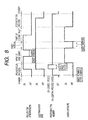
- Fig. 8 is a timing chart in this embodiment (1 to 2).
- the electrification for the period of one peripheral length before image formation is conducted at double the process speed in Embodiment 1, that is, 300 mm/sec
- (A') + (B) + (C) about 2.4 sec.
- the distance L between the transfer nip portion 7c and the pair of rollers for synchronizing 50 is 100 mm.
- the peripheral velocity of the photosensitive member 1 is increased to 300 mm/sec for a predetermined time in this embodiment.
- the rate of velocity increase is not limited to the numerical value in this embodiment.
- the optimum rate of increase varies according to a system and kind of the photosensitive member, a system and kind of the electrifying member, the process speed, and the like.
- the peripheral velocity of the photosensitive member 1 is changed in this embodiment.
- the same effect can be obtained also when the speed at which the recording material P moves from the position of the pair of rollers for synchronizing 50 to the transfer nip portion 7c is made variable.
- the speed at which the tip end of the first recording material P moves from the position of the pair of rollers for synchronizing 50 to the transfer nip portion 7c is set at half the process speed, that is, 75 mm/sec, the same effect can be obtained.
- control may be conducted at the optimum speed by suitably combining these configurations.
- Embodiments 1 and 2 In the case where, besides the processing such as accumulation and expansion of the input image data input to the image forming apparatus as described in Embodiments 1 and 2, image formation is caused to wait until the temperature of the fixing apparatus reaches a level required for effecting fixation, or in the case where image formation is caused to wait until the completion of expansion of the input image data in case of using the image forming apparatus as a printer, excessive electrification of the photosensitive member is prevented by applying Embodiments 1 and 2. As a result, power consumption of the electrification power source can be reduced, occurrence of the image defect and lowering of the photosensitive member life can be prevented, and the number of sheets for which image formation can be performed per unit time, that is, productivity can be maintained as well.
- the contact electrifying member 2 is not limited to a roller type, and may be a contact electrifying member with other form, such as blade type, rod type, brush type or magnetic brush type.
- the structure may also be adopted in which, as described above, the electrifying member and the image bearing member surface are not in contact with each other with pressing force but are arranged extremely close to, yet not in contact with, each other provided that a dischargeable area determined by a gap to gap voltage and a Paschen curve is secured between both the members. In the present invention, this also falls under the category of contact electrification.
- a waveform of an alternating voltage a sine wave, a rectangular wave, a triangular wave or the like can be appropriately used.
- alternating voltage a constant voltage or a direct current electric field that has undergone a constant-current control can also be used.
- image exposure means other appropriate exposure means or mechanism can be used such as a slit exposure means of an original image.
- the contact electrification system transferring means is a conductive transferring roller in the above embodiments, but is not limited to a roller type. Other rotary member of a belt type or the like can also be used. A transfer corona discharge device may also be used.
- the image bearing member may be an electrostatic recording dielectric or the like.
- the dielectric surface is primarily electrified uniformly to predetermined polarity and potential, and then selectively charge-removed by a charge-removal means such as a charge-removal stylus head or an electronic gun, to thereby form a target electrostatic latent image on the dielectric surface.
Landscapes
- Physics & Mathematics (AREA)
- Engineering & Computer Science (AREA)
- Plasma & Fusion (AREA)
- General Physics & Mathematics (AREA)
- Electrostatic Charge, Transfer And Separation In Electrography (AREA)
Abstract
Description
| DC component | -500 V |
| AC component | frequency of 1800 Hz, |
| Vpp (peak to peak) of 1400 V |
Claims (9)
- An image forming apparatus comprising:an image bearing member;electrifying means for electrifying said image bearing member;image forming means for forming an image on said image bearing member electrified by said electrifying means;conveying means for making a recording material, which has been conveyed from a recording material receiving portion, wait and then conveying the image on said image bearing member to a transfer portion for transferring the image onto the recording material; andcontrol means for controlling timing for starting electrification by said electrifying means in accordance with start timing of conveyance of the recording material by said conveying means.
- An image forming apparatus according to claim 1, wherein a waiting time of the recording material by said conveying means is variable.
- An image forming apparatus according to claim 2, wherein a waiting time of the recording material by said conveying means is variable in accordance with an image forming mode.
- An image forming apparatus according to claim 3, further comprising processing means for image-processing input image data, wherein said image forming means is provided with exposure means for exposing said image bearing member on the basis of output image data that has been image-processed by said processing means.
- An image forming apparatus according to claim 4, wherein the waiting time is longer in the case where the input image data is output to said exposure means after being processed by said processing means than that in the case where the input image data is output to said exposure means without having been processed by said processing means.
- An image forming apparatus according to claim 4, wherein the waiting time of the recording material by said conveying means is variable in accordance with the number of density levels of the output image data with respect to the input image data.
- An image forming apparatus according to claim 2, wherein the waiting time of the recording material by said conveying means is variable in accordance with an amount of input image data.
- An image forming apparatus according to claim 7, further comprising processing means for image-processing input image data, wherein said image forming means is provided with exposing means for exposing said image bearing member on the basis of the image data that has been image-processed by said processing means, and a processing time by said processing means varies in accordance with the amount of input image data.
- An image forming apparatus according to claim 1 or 2, wherein a bias in which an AC bias is superimposed on a DC bias is applied in the state where said electrifying means contacts said image bearing member.
Applications Claiming Priority (2)
| Application Number | Priority Date | Filing Date | Title |
|---|---|---|---|
| JP2001041906 | 2001-02-19 | ||
| JP2001041906 | 2001-02-19 |
Publications (2)
| Publication Number | Publication Date |
|---|---|
| EP1233308A2 true EP1233308A2 (en) | 2002-08-21 |
| EP1233308A3 EP1233308A3 (en) | 2009-04-29 |
Family
ID=18904279
Family Applications (1)
| Application Number | Title | Priority Date | Filing Date |
|---|---|---|---|
| EP02003654A Withdrawn EP1233308A3 (en) | 2001-02-19 | 2002-02-18 | Image forming apparatus |
Country Status (2)
| Country | Link |
|---|---|
| US (1) | US6694110B2 (en) |
| EP (1) | EP1233308A3 (en) |
Families Citing this family (5)
| Publication number | Priority date | Publication date | Assignee | Title |
|---|---|---|---|---|
| KR100449746B1 (en) * | 2002-11-22 | 2004-09-22 | 삼성전자주식회사 | Method and apparatus for controlling image input and record-medium supply of image processing apparatus |
| JP2007114757A (en) * | 2005-09-21 | 2007-05-10 | Canon Inc | Image forming apparatus |
| JP4871682B2 (en) * | 2005-09-21 | 2012-02-08 | キヤノン株式会社 | Image forming apparatus |
| JP2010116234A (en) * | 2008-11-12 | 2010-05-27 | Ricoh Co Ltd | Image forming device, control method of the same, and printed medium conveying device |
| JP6260476B2 (en) * | 2013-10-10 | 2018-01-17 | 京セラドキュメントソリューションズ株式会社 | Image forming apparatus |
Family Cites Families (10)
| Publication number | Priority date | Publication date | Assignee | Title |
|---|---|---|---|---|
| JP2675811B2 (en) * | 1988-04-20 | 1997-11-12 | キヤノン株式会社 | Light beam printer |
| JPH03269551A (en) * | 1990-03-20 | 1991-12-02 | Matsushita Electric Ind Co Ltd | electrophotographic equipment |
| EP0457330B1 (en) * | 1990-05-17 | 2000-02-09 | Canon Kabushiki Kaisha | Image forming apparatus |
| JPH05323708A (en) * | 1992-05-22 | 1993-12-07 | Murata Mach Ltd | Image forming device |
| JPH07325529A (en) * | 1994-06-01 | 1995-12-12 | Brother Ind Ltd | Printer |
| JPH08160828A (en) * | 1994-12-07 | 1996-06-21 | Canon Inc | Electrophotographic printer |
| US5978643A (en) * | 1996-03-21 | 1999-11-02 | Ricoh Company, Ltd. | Electrophotographic apparatus which reduces running cost by starting image forming processes in response to sheet detectors |
| JP3587002B2 (en) * | 1996-12-09 | 2004-11-10 | 富士ゼロックス株式会社 | Image forming apparatus and image forming method |
| JP3428379B2 (en) * | 1997-07-11 | 2003-07-22 | シャープ株式会社 | Image forming device |
| JP3985405B2 (en) * | 1999-12-02 | 2007-10-03 | ブラザー工業株式会社 | Image forming apparatus |
-
2002
- 2002-02-11 US US10/068,840 patent/US6694110B2/en not_active Expired - Lifetime
- 2002-02-18 EP EP02003654A patent/EP1233308A3/en not_active Withdrawn
Also Published As
| Publication number | Publication date |
|---|---|
| US6694110B2 (en) | 2004-02-17 |
| EP1233308A3 (en) | 2009-04-29 |
| US20020159783A1 (en) | 2002-10-31 |
Similar Documents
| Publication | Publication Date | Title |
|---|---|---|
| US5179397A (en) | Image forming apparatus with constant voltage and constant current control | |
| JP4663814B2 (en) | Image forming apparatus | |
| JPH0915976A (en) | Developing device | |
| JP3131286B2 (en) | Electrophotographic printer | |
| JP2004333789A (en) | Image forming device | |
| US5504565A (en) | Image forming apparatus having transfer voltage timing control | |
| US6694110B2 (en) | Image forming apparatus with variable waiting time conveyance feature | |
| JP2614309B2 (en) | Image forming device | |
| JP4532879B2 (en) | Image forming apparatus | |
| JP4125015B2 (en) | Image forming apparatus | |
| JPH07114262A (en) | Developing device | |
| JPH10198131A (en) | Charging device and image forming device | |
| JPH05307315A (en) | Image forming device | |
| JP3232762B2 (en) | Image forming device | |
| KR100419408B1 (en) | Charging voltage control device of image forming apparatus | |
| JP2004029100A (en) | Image forming device | |
| US6370345B2 (en) | Image forming apparatus and image forming method employing the same | |
| US7907871B2 (en) | Image forming apparatus | |
| JPH08146677A (en) | Image forming method | |
| JP2002148964A (en) | Image forming device | |
| JP3332835B2 (en) | Image forming device | |
| JPH09127765A (en) | Image forming device | |
| JP2003280296A (en) | Image forming device | |
| JPH117207A (en) | Image forming device | |
| JP3630954B2 (en) | Image forming apparatus |
Legal Events
| Date | Code | Title | Description |
|---|---|---|---|
| PUAI | Public reference made under article 153(3) epc to a published international application that has entered the european phase |
Free format text: ORIGINAL CODE: 0009012 |
|
| AK | Designated contracting states |
Kind code of ref document: A2 Designated state(s): AT BE CH CY DE DK ES FI FR GB GR IE IT LI LU MC NL PT SE TR |
|
| AX | Request for extension of the european patent |
Free format text: AL;LT;LV;MK;RO;SI |
|
| PUAL | Search report despatched |
Free format text: ORIGINAL CODE: 0009013 |
|
| AK | Designated contracting states |
Kind code of ref document: A3 Designated state(s): AT BE CH CY DE DK ES FI FR GB GR IE IT LI LU MC NL PT SE TR |
|
| AX | Request for extension of the european patent |
Extension state: AL LT LV MK RO SI |
|
| 17P | Request for examination filed |
Effective date: 20051017 |
|
| 17Q | First examination report despatched |
Effective date: 20090616 |
|
| AKX | Designation fees paid |
Designated state(s): DE FR GB IT |
|
| STAA | Information on the status of an ep patent application or granted ep patent |
Free format text: STATUS: THE APPLICATION HAS BEEN WITHDRAWN |
|
| 18W | Application withdrawn |
Effective date: 20160204 |