EP1233273A2 - Device for monitoring electromagnetic fields - Google Patents
Device for monitoring electromagnetic fields Download PDFInfo
- Publication number
- EP1233273A2 EP1233273A2 EP02002685A EP02002685A EP1233273A2 EP 1233273 A2 EP1233273 A2 EP 1233273A2 EP 02002685 A EP02002685 A EP 02002685A EP 02002685 A EP02002685 A EP 02002685A EP 1233273 A2 EP1233273 A2 EP 1233273A2
- Authority
- EP
- European Patent Office
- Prior art keywords
- accordance
- electromagnetic field
- communication interface
- monitoring
- selectively
- Prior art date
- Legal status (The legal status is an assumption and is not a legal conclusion. Google has not performed a legal analysis and makes no representation as to the accuracy of the status listed.)
- Granted
Links
Images
Classifications
-
- G—PHYSICS
- G01—MEASURING; TESTING
- G01R—MEASURING ELECTRIC VARIABLES; MEASURING MAGNETIC VARIABLES
- G01R29/00—Arrangements for measuring or indicating electric quantities not covered by groups G01R19/00 - G01R27/00
- G01R29/08—Measuring electromagnetic field characteristics
- G01R29/0864—Measuring electromagnetic field characteristics characterised by constructional or functional features
- G01R29/0871—Complete apparatus or systems; circuits, e.g. receivers or amplifiers
Definitions
- the present invention relates to devices for monitoring electromagnetic fields and was developed with particular attention to potential application in monitoring the level, or in other words the strength, of ambient electromagnetic fields.
- a known method of performing such a monitoring function is to use measuring instruments which are carried by an operator to the site where the strength of an electromagnetic field is to be determined. Often, after a first rough measurement of approximate E-field strength made using a small portable instrument, it is necessary to proceed with more accurate measurements using more sophisticated instruments.
- the object of the present invention is thus to provide a solution capable of satisfying all of the needs indicated above.
- this object is achieved by means of a device having the characteristics detailed in the following claims.
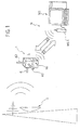
- a monitoring device in accordance with the invention is intended to measure the electromagnetic field at a site designated generically by the letter L.
- the electromagnetic field derives from the overlapping electromagnetic fields produced by a more or less large number of sources, one of which is illustrated schematically and designated by the letter S.
- the sources in question may be said to consist, for example, of:
- An important characteristic of the device 1 in accordance with the invention is that it makes it possible to perform a remote monitoring function, or in other words without requiring that an operator be present at the site L where the device 1 is installed.
- the device 1 is capable of interfacing in a telecommunications network N (e.g., a mobile telephony network) in order to transmit and/or receive data to and from a remote station WS which can be manned or in any case periodically supervised by an operator.
- a telecommunications network N e.g., a mobile telephony network
- references A1, A2 and A3 designate three antennas (implemented using any known technology, e.g., in the form of whip, dipole or loop antennas) oriented with their respective directions of maximum sensitivity lying in different directions, and typically along three directions corresponding to the X, Y and Z axes of an orthogonal or Cartesian coordinate system (see Figure 1).
- This arrangement is such that the electric and/or magnetic components of the ambient electromagnetic field can be sensed independently of whether electromagnetic fields whose polarization is predominately in a single direction are present, this being a situation that can, for example, occur near transmitters which emit an electromagnetic wave with a predetermined vertical or horizontal polarization plane.
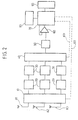
- Reference 10 designates a band selector device designed to act in accordance with the prior art on antennas A1, A2 and A3 and/or on the reception chain associated with them in such a way as to make device 1 exclusively (or at least prevalently) sensitive to the electromagnetic field in at least two frequency ranges or bands, for example the UHF band for monitoring the electromagnetic field associated with emissions from terrestrial radio and television transmitters, the band used by GSM systems for monitoring the signal strength deriving from coverage of site L on the part of one or more mobile telephony networks, etc.
- the selector unit 10 (which in practice selects the band in which monitoring is to be performed) operates in response to a command signal received over a line 101 from a control unit which will be described in further detail below.
- the band selector unit 10 is provided with a set of cascaded filter units 20 which operate separately on the signals from each of the antennas A1, A2 and A3 and are intended to increase the accuracy and selectivity with which the electromagnetic field is measured in the band taken into consideration.
- References 30 designate radio-frequency rectifier units, which like filters 20 are implemented in accordance with the prior art.
- Each of the rectifier units 30 receives the output signal from the filter 20 located immediately upstream and, at its own output, generates a rectified signal corresponding in practice to the envelope of the radio-frequency signal provided at its input.
- each rectifier 30 thus provides a signal which is indicative of the electromagnetic field strength measured in the main direction of sensitivity of the associated antenna A1, A2 and A3 in the frequency range or band selected on each occasion by means of band selector 10.
- the field strength signals generated by rectifiers 30 are sent to a multiplexer unit 40 whose function is to permit the various field strength signals to be processed using a time division scheme. This takes place under the control of a command signal supplied over a line 401 from the control unit mentioned above.
- each of the aforesaid field strength signals can, at least in principle, be analyzed and handled independently by separate processing and handling setups.
- Reference 50 designates an analog-to-digital converter whereby the various output signals from rectifiers 30 are converted into digital form for subsequent processing.
- This processing essentially involves comparing the various field strength signals with one or more threshold levels applied to a threshold comparator 60.
- this threshold level or levels will be established by the control unit mentioned above.
- This unit designated by the number 70 in the diagram shown in Figure 2, preferably consists of a microcontroller or similar processing device carrying an associated memory block 80.
- the latter usually comprises, in accordance with a well-known solution, a ROM memory for storing configuration and program instructions, and a RAM memory for storing the input/output data from device 1.
- reference 90 designates a communication module capable of being configured, for example, in the form of a modem such as a GSM modem operating with an RS232 serial interface so that data can be transmitted between the device 1 and the remote station WS, which is equipped for this purpose with a modem WS1.
- a modem such as a GSM modem operating with an RS232 serial interface
- a bidirectional connection can be established between the device 1 and the station WS whereby the device 1 can transmit, for example, data corresponding to the measurements made and any alarm signals (field strength beyond the thresholds, etc.) to the station WS.
- the station WS can transmit requests to perform measurements, band selection data, measurement threshold data and so forth to the device 1.
- the structure as described provides a high degree of flexibility in performing monitoring activities.
- control unit 70 is capable of operating (e.g., in response to instructions received from the station WS) in such a way as to selectively vary:
- monitoring can be performed with specific reference to different and clearly identified sources of electromagnetic fields.
- the threshold level or levels with which the element 60 operates is (are) capable of being changed, for example in order to take different needs into account (e.g., where different signal levels are to be monitored for different frequency ranges or bands, and thus for different sources).
- the device 1 lends itself readily to being implemented in such a way that it can be maintained in standby status (with minimum power consumption) and then activated by means of a command transmitted by the station WS, so that monitoring can be carried out at predetermined times, e.g., in accordance with a polling scheme applied to a number of devices 1 in different locations.
- the device 1 can be implemented as a mobile device (e.g., as part of a network N which is a mobile radio network) and/or as a low power consumption device makes it possible to use the device 1 as a flexible measurement instrument capable of being readily located in widely dissimilar sites L (and if necessary at successive times) without having to provide special power supply units and/or communication terminals at the site, thus facilitating the deployment of geographically distributed monitoring networks.
- a mobile device e.g., as part of a network N which is a mobile radio network
- a low power consumption device makes it possible to use the device 1 as a flexible measurement instrument capable of being readily located in widely dissimilar sites L (and if necessary at successive times) without having to provide special power supply units and/or communication terminals at the site, thus facilitating the deployment of geographically distributed monitoring networks.
Landscapes
- Physics & Mathematics (AREA)
- Electromagnetism (AREA)
- General Physics & Mathematics (AREA)
- Monitoring And Testing Of Transmission In General (AREA)
- Mobile Radio Communication Systems (AREA)
- Near-Field Transmission Systems (AREA)
- Synchronous Machinery (AREA)
- Control Of Eletrric Generators (AREA)
- Burglar Alarm Systems (AREA)
- Testing Electric Properties And Detecting Electric Faults (AREA)
Abstract
Description
- The ability to perform selective monitoring for different frequency ranges or bandwidths, and thus distinguish and identify the various sources in relation to their contributions to overall electromagnetic field strength,
- The ability to perform monitoring whose purpose is to determine when predetermined E-field strength thresholds are reached, rather than to measure the field and its strength on a continuous basis,
- The ability to implement a remote monitoring function, thus avoiding the need to access the site where the monitoring station is installed, with the further ability to selectively and remotely vary monitoring parameters such as the threshold levels taken into consideration, and
- The ability, which is closely linked to the capabilities cited in the previous paragraph, to use measurement and monitoring points which can be freely and readily located in widely dissimilar positions in order to set up a geographically distributed monitoring network.
In accordance with the present invention, this object is achieved by means of a device having the characteristics detailed in the following claims.
- Figure 1 provides a general illustration of the context in which a device in accordance with the invention is used, and
- Figure 2 is a block diagram illustrating the circuitry of a device in accordance with the invention.
- Radio and/or television transmitters (which, at least in urban areas with large concentrations of broadcasters, are the most significant source of detectable ambient electromagnetic fields),
- Telecommunications system transmitters, e.g., for mobile telephony,
- Miscellaneous sources such as remote-control units, dedicated generators of electromagnetic waves of various kinds, etc.
- The band selected by the
selector 10, and hence the frequency range in which monitoring is performed, and - The threshold level applied in
device 60.
Claims (10)
- A device for monitoring electromagnetic fields, characterized in that it comprises:and in that said device also exhibits at least one of the following characteristics:At least one antenna element (A1, A2, A3) for electromagnetic field measurements,A reception chain (10, 20, 30) capable of generating at least one signal which is indicative of the electromagnetic field strength measured by said at least one antenna element (A1, A2, A3),A threshold comparator element (60) for comparing said at least one field strength signal generated by said reception chain (20, 30, 40) with at least one associated threshold level,A selector element (10) provided to make the device (1) selectively sensitive to at least two electromagnetic field frequency bands,Said at least one threshold level of said threshold comparator element (60) being selectively variable, andA communication interface (90) provided so that signals can be transmitted to and/or from the device (10).
- A device in accordance with claim 1, characterized in that it comprises a plurality of antenna elements (A1, A2, A3) whose sensitivity is oriented in different directions.
- A device in accordance with claim 2, characterized in that it comprises at least three antenna elements (A1, A2, A3) whose respective directions of sensitivity are oriented along a set of three mutually orthogonal axes (X, Y, Z).
- A device in accordance with any of claims 1 through 3, characterized in that it comprises said selector element (10) and in that said selector element (10) is capable of making the device (1) sensitive to the electromagnetic field in at least one band selected from the group consisting of the frequency bands used for radio and television transmission and of the transmission bands used by mobile communications networks.
- A device in accordance with claim 2, characterized in that the antenna elements in said plurality (A1, A2, A3) are each associated with separate reception chains (20, 30), the device also comprising a multiplexer element (40) for handling the signals generated by said separate reception chains (20, 30) using a general time division multiplexing scheme.
- A device in accordance with any of the foregoing claims, characterized in that it comprises a control unit (70) configured so as to selectively vary at least one selected parameter in the group consisting of:The frequency band selected by said selector element (10),Said one or more threshold levels for the threshold comparator element (60).
- A device in accordance with claim 6, characterized in that said one or more control units (70) can be configured to selectively vary said one or more magnitudes in relation to the signals received from said communication interface (90).
- A device in accordance with any of the foregoing claims, characterized in that it comprises said communication interface (90), said communication interface being configured as an interface for communication with a mobile communication interface.
- A device in accordance with claim 1 or with claim 8, characterized in that said communication interface (90) operates as a serial interface, preferably according to the RS232 standard.
- A device in accordance with any of the foregoing claims, integrated together with like devices in a geographically distributed electromagnetic field monitoring network.
Applications Claiming Priority (2)
| Application Number | Priority Date | Filing Date | Title |
|---|---|---|---|
| IT2001TO000152A ITTO20010152A1 (en) | 2001-02-20 | 2001-02-20 | ELECTROMAGNETIC FIELD MONITORING DEVICE. |
| ITTO010152 | 2001-02-20 |
Publications (3)
| Publication Number | Publication Date |
|---|---|
| EP1233273A2 true EP1233273A2 (en) | 2002-08-21 |
| EP1233273A3 EP1233273A3 (en) | 2003-09-24 |
| EP1233273B1 EP1233273B1 (en) | 2006-10-04 |
Family
ID=11458592
Family Applications (1)
| Application Number | Title | Priority Date | Filing Date |
|---|---|---|---|
| EP02002685A Expired - Lifetime EP1233273B1 (en) | 2001-02-20 | 2002-02-06 | Device for monitoring electromagnetic fields |
Country Status (5)
| Country | Link |
|---|---|
| EP (1) | EP1233273B1 (en) |
| AT (1) | ATE341764T1 (en) |
| DE (1) | DE60215065T2 (en) |
| ES (1) | ES2273928T3 (en) |
| IT (1) | ITTO20010152A1 (en) |
Cited By (15)
| Publication number | Priority date | Publication date | Assignee | Title |
|---|---|---|---|---|
| WO2004086066A1 (en) * | 2003-03-26 | 2004-10-07 | Telecom Italia S.P.A. | Device, system and method for monitoring electromagnetic fields |
| EP1542027A1 (en) * | 2003-12-11 | 2005-06-15 | Antennessa | Device for measuring of ambiant radiation |
| RU2254584C1 (en) * | 2003-11-26 | 2005-06-20 | Тюняев Владимир Николаевич | Device for inspecting protection against electromagnetic field |
| EP1605270A1 (en) * | 2004-06-09 | 2005-12-14 | France Telecom | Antenna for measuring the ambient electromagnetic field |
| CN100351635C (en) * | 2004-08-20 | 2007-11-28 | 虹光精密工业(苏州)有限公司 | Electromagnetic wave detecting system |
| CN100426907C (en) * | 2004-07-23 | 2008-10-15 | 中兴通讯股份有限公司 | Wired connection measuring method for power consumption time of CDMA mobile terminal |
| CN100433878C (en) * | 2004-07-27 | 2008-11-12 | 中兴通讯股份有限公司 | A wired connection measurement method for CDMA mobile terminal standby time |
| WO2009087599A3 (en) * | 2008-01-09 | 2009-09-03 | Nxp B.V. | Evaluating an electromagnetic field strength of an electromagnetic gate apparatus |
| CN1691683B (en) * | 2004-04-28 | 2010-04-28 | 中兴通讯股份有限公司 | A method for measuring the power consumption time of a CDMA mobile terminal |
| ES2363149A1 (en) * | 2010-12-30 | 2011-07-21 | Universidad Politécnica de Madrid | REMOTE STATION, SYSTEM AND METHOD OF MONITORING OF ENVIRONMENTAL ELECTROMAGNETIC FIELD IN REAL TIME. |
| GB2513640A (en) * | 2013-05-02 | 2014-11-05 | Intertek Group Plc | Improved RF detector |
| EP2481002A4 (en) * | 2009-09-24 | 2017-03-22 | Wave Guard Technologies Ltd | A system and method of online radiation management and control of non-ionizing radiation sources |
| EP2531865A4 (en) * | 2010-01-26 | 2018-04-04 | Power Survey LLC | Method and apparatus for discrimination of sources in stray voltage detection |
| CN113311251A (en) * | 2021-07-01 | 2021-08-27 | 北京森馥科技股份有限公司 | Electromagnetic radiation monitoring method and electromagnetic radiation monitoring system |
| CN115412448A (en) * | 2022-08-24 | 2022-11-29 | 中国联合网络通信集团有限公司 | Network equipment security assessment method, device and storage medium |
Family Cites Families (4)
| Publication number | Priority date | Publication date | Assignee | Title |
|---|---|---|---|---|
| US5295072A (en) * | 1992-04-29 | 1994-03-15 | Bfgoodrich Flightsystems, Inc. | Sampled data lightning strike detection and mapping system capable of recovering a pre threshold sample history for detection and mapping processing |
| JPH0843465A (en) * | 1994-08-03 | 1996-02-16 | Sony Tektronix Corp | Radio monitoring equipment |
| JPH10227819A (en) * | 1997-02-17 | 1998-08-25 | Kitagawa Ind Co Ltd | Electromagnetic wave intensity warning device |
| DE19722350A1 (en) * | 1997-05-28 | 1998-12-03 | Michael Scharf | Radio interference meter for monitoring electromagnetic radiation from electrical installation |
-
2001
- 2001-02-20 IT IT2001TO000152A patent/ITTO20010152A1/en unknown
-
2002
- 2002-02-06 EP EP02002685A patent/EP1233273B1/en not_active Expired - Lifetime
- 2002-02-06 AT AT02002685T patent/ATE341764T1/en not_active IP Right Cessation
- 2002-02-06 ES ES02002685T patent/ES2273928T3/en not_active Expired - Lifetime
- 2002-02-06 DE DE60215065T patent/DE60215065T2/en not_active Expired - Lifetime
Cited By (21)
| Publication number | Priority date | Publication date | Assignee | Title |
|---|---|---|---|---|
| US7859247B2 (en) | 2003-03-26 | 2010-12-28 | Telecom Italia S.P.A. | Device, system and method for monitoring electromagnetic fields |
| WO2004086066A1 (en) * | 2003-03-26 | 2004-10-07 | Telecom Italia S.P.A. | Device, system and method for monitoring electromagnetic fields |
| RU2254584C1 (en) * | 2003-11-26 | 2005-06-20 | Тюняев Владимир Николаевич | Device for inspecting protection against electromagnetic field |
| EP1542027A1 (en) * | 2003-12-11 | 2005-06-15 | Antennessa | Device for measuring of ambiant radiation |
| WO2005059575A1 (en) * | 2003-12-11 | 2005-06-30 | Antennessa | Device for measuring ambient electromagnetic radiation |
| CN1691683B (en) * | 2004-04-28 | 2010-04-28 | 中兴通讯股份有限公司 | A method for measuring the power consumption time of a CDMA mobile terminal |
| WO2006003303A1 (en) * | 2004-06-09 | 2006-01-12 | France Telecom | Antenna for measuring ambient electromagnetic radiation |
| EP1605270A1 (en) * | 2004-06-09 | 2005-12-14 | France Telecom | Antenna for measuring the ambient electromagnetic field |
| CN100426907C (en) * | 2004-07-23 | 2008-10-15 | 中兴通讯股份有限公司 | Wired connection measuring method for power consumption time of CDMA mobile terminal |
| CN100433878C (en) * | 2004-07-27 | 2008-11-12 | 中兴通讯股份有限公司 | A wired connection measurement method for CDMA mobile terminal standby time |
| CN100351635C (en) * | 2004-08-20 | 2007-11-28 | 虹光精密工业(苏州)有限公司 | Electromagnetic wave detecting system |
| US8381980B2 (en) | 2008-01-09 | 2013-02-26 | Nxp B.V. | Evaluating an electromagnetic field strength of an electromagnetic gate apparatus |
| WO2009087599A3 (en) * | 2008-01-09 | 2009-09-03 | Nxp B.V. | Evaluating an electromagnetic field strength of an electromagnetic gate apparatus |
| EP2481002A4 (en) * | 2009-09-24 | 2017-03-22 | Wave Guard Technologies Ltd | A system and method of online radiation management and control of non-ionizing radiation sources |
| EP2531865A4 (en) * | 2010-01-26 | 2018-04-04 | Power Survey LLC | Method and apparatus for discrimination of sources in stray voltage detection |
| US10338106B2 (en) | 2010-01-26 | 2019-07-02 | Power Survey Llc | Method and apparatus for discrimination of sources in stray voltage detection |
| US10871509B2 (en) | 2010-01-26 | 2020-12-22 | Osmose Utilities Services, Inc. | Method and apparatus for discrimination of sources in stray voltage detection |
| ES2363149A1 (en) * | 2010-12-30 | 2011-07-21 | Universidad Politécnica de Madrid | REMOTE STATION, SYSTEM AND METHOD OF MONITORING OF ENVIRONMENTAL ELECTROMAGNETIC FIELD IN REAL TIME. |
| GB2513640A (en) * | 2013-05-02 | 2014-11-05 | Intertek Group Plc | Improved RF detector |
| CN113311251A (en) * | 2021-07-01 | 2021-08-27 | 北京森馥科技股份有限公司 | Electromagnetic radiation monitoring method and electromagnetic radiation monitoring system |
| CN115412448A (en) * | 2022-08-24 | 2022-11-29 | 中国联合网络通信集团有限公司 | Network equipment security assessment method, device and storage medium |
Also Published As
| Publication number | Publication date |
|---|---|
| DE60215065D1 (en) | 2006-11-16 |
| ITTO20010152A1 (en) | 2002-08-20 |
| EP1233273B1 (en) | 2006-10-04 |
| ITTO20010152A0 (en) | 2001-02-20 |
| DE60215065T2 (en) | 2007-05-10 |
| ES2273928T3 (en) | 2007-05-16 |
| ATE341764T1 (en) | 2006-10-15 |
| EP1233273A3 (en) | 2003-09-24 |
Similar Documents
| Publication | Publication Date | Title |
|---|---|---|
| EP1233273B1 (en) | Device for monitoring electromagnetic fields | |
| US4728959A (en) | Direction finding localization system | |
| EP0133378B1 (en) | Distress radiolocation method and system | |
| KR100378613B1 (en) | Antenna and Feeder Cable Testing Apparatus and Method | |
| US6005891A (en) | System for testing signal transmission/reception apparatus | |
| DE69522902D1 (en) | METHOD AND DEVICE FOR SELECTING TWO ANTENNAS FOR RECEIVING A COMMUNICATION SIGNAL | |
| CN101895903A (en) | Radio communication device, wireless communication system and wireless communications method | |
| KR20000070406A (en) | A communication system, a primary radio station, a secondary radio station, and a communication method | |
| EP1488532B1 (en) | Method and apparatus for implementing smart antennas and diversity techniques | |
| EP3809162B1 (en) | Gnss receiving device and gnss receiving method | |
| SK164498A3 (en) | Method of transmitting and receiving data, system and receiver therefor | |
| USRE50326E1 (en) | Monitoring system for a distributed antenna system | |
| JP2001520387A (en) | Monitoring method and monitoring device | |
| US7859247B2 (en) | Device, system and method for monitoring electromagnetic fields | |
| CN113884988A (en) | A radar communication integrated monitoring method, receiving front end and monitoring system | |
| CA2452830A1 (en) | Method and apparatus for real time testing of dtv antenna transmitting systems in time domain under full power | |
| JPH07273518A (en) | Antenna fall alarm | |
| KR100295896B1 (en) | Antenna station and method for receiving short pulses, and apparatus for detecting wireless signal origination location using the method and method | |
| Carbonell et al. | Development of a stand-alone and scalable weather monitoring system using two-way VHF radios | |
| JPH10160775A (en) | How to measure satellite-borne antenna patterns | |
| JPS6047973A (en) | Individual detecting system | |
| RU19624U1 (en) | MOBILE INFORMATION TRANSMISSION SYSTEM | |
| JPH03101526A (en) | Satellite channel monitoring system | |
| Khotamov et al. | Monitoring the radio-frequency spectran-based integrated antenna system | |
| US3048839A (en) | Survivor locator system |
Legal Events
| Date | Code | Title | Description |
|---|---|---|---|
| PUAI | Public reference made under article 153(3) epc to a published international application that has entered the european phase |
Free format text: ORIGINAL CODE: 0009012 |
|
| AK | Designated contracting states |
Kind code of ref document: A2 Designated state(s): AT BE CH CY DE DK ES FI FR GB GR IE IT LI LU MC NL PT SE TR |
|
| AX | Request for extension of the european patent |
Free format text: AL;LT;LV;MK;RO;SI |
|
| RAP1 | Party data changed (applicant data changed or rights of an application transferred) |
Owner name: TELECOM ITALIA S.P.A. |
|
| PUAL | Search report despatched |
Free format text: ORIGINAL CODE: 0009013 |
|
| AK | Designated contracting states |
Kind code of ref document: A3 Designated state(s): AT BE CH CY DE DK ES FI FR GB GR IE IT LI LU MC NL PT SE TR |
|
| AX | Request for extension of the european patent |
Extension state: AL LT LV MK RO SI |
|
| 17P | Request for examination filed |
Effective date: 20040304 |
|
| AKX | Designation fees paid |
Designated state(s): AT BE CH CY DE DK ES FI FR GB GR IE IT LI LU MC NL PT SE TR |
|
| GRAP | Despatch of communication of intention to grant a patent |
Free format text: ORIGINAL CODE: EPIDOSNIGR1 |
|
| GRAS | Grant fee paid |
Free format text: ORIGINAL CODE: EPIDOSNIGR3 |
|
| GRAA | (expected) grant |
Free format text: ORIGINAL CODE: 0009210 |
|
| AK | Designated contracting states |
Kind code of ref document: B1 Designated state(s): AT BE CH CY DE DK ES FI FR GB GR IE IT LI LU MC NL PT SE TR |
|
| PG25 | Lapsed in a contracting state [announced via postgrant information from national office to epo] |
Ref country code: IT Free format text: LAPSE BECAUSE OF FAILURE TO SUBMIT A TRANSLATION OF THE DESCRIPTION OR TO PAY THE FEE WITHIN THE PRESCRIBED TIME-LIMIT;WARNING: LAPSES OF ITALIAN PATENTS WITH EFFECTIVE DATE BEFORE 2007 MAY HAVE OCCURRED AT ANY TIME BEFORE 2007. THE CORRECT EFFECTIVE DATE MAY BE DIFFERENT FROM THE ONE RECORDED. Effective date: 20061004 Ref country code: CH Free format text: LAPSE BECAUSE OF FAILURE TO SUBMIT A TRANSLATION OF THE DESCRIPTION OR TO PAY THE FEE WITHIN THE PRESCRIBED TIME-LIMIT Effective date: 20061004 Ref country code: AT Free format text: LAPSE BECAUSE OF FAILURE TO SUBMIT A TRANSLATION OF THE DESCRIPTION OR TO PAY THE FEE WITHIN THE PRESCRIBED TIME-LIMIT Effective date: 20061004 Ref country code: BE Free format text: LAPSE BECAUSE OF FAILURE TO SUBMIT A TRANSLATION OF THE DESCRIPTION OR TO PAY THE FEE WITHIN THE PRESCRIBED TIME-LIMIT Effective date: 20061004 Ref country code: FI Free format text: LAPSE BECAUSE OF FAILURE TO SUBMIT A TRANSLATION OF THE DESCRIPTION OR TO PAY THE FEE WITHIN THE PRESCRIBED TIME-LIMIT Effective date: 20061004 Ref country code: LI Free format text: LAPSE BECAUSE OF FAILURE TO SUBMIT A TRANSLATION OF THE DESCRIPTION OR TO PAY THE FEE WITHIN THE PRESCRIBED TIME-LIMIT Effective date: 20061004 Ref country code: NL Free format text: LAPSE BECAUSE OF FAILURE TO SUBMIT A TRANSLATION OF THE DESCRIPTION OR TO PAY THE FEE WITHIN THE PRESCRIBED TIME-LIMIT Effective date: 20061004 |
|
| REG | Reference to a national code |
Ref country code: GB Ref legal event code: FG4D |
|
| REG | Reference to a national code |
Ref country code: CH Ref legal event code: EP |
|
| REG | Reference to a national code |
Ref country code: IE Ref legal event code: FG4D |
|
| REF | Corresponds to: |
Ref document number: 60215065 Country of ref document: DE Date of ref document: 20061116 Kind code of ref document: P |
|
| PG25 | Lapsed in a contracting state [announced via postgrant information from national office to epo] |
Ref country code: DK Free format text: LAPSE BECAUSE OF FAILURE TO SUBMIT A TRANSLATION OF THE DESCRIPTION OR TO PAY THE FEE WITHIN THE PRESCRIBED TIME-LIMIT Effective date: 20070104 Ref country code: SE Free format text: LAPSE BECAUSE OF FAILURE TO SUBMIT A TRANSLATION OF THE DESCRIPTION OR TO PAY THE FEE WITHIN THE PRESCRIBED TIME-LIMIT Effective date: 20070104 |
|
| PG25 | Lapsed in a contracting state [announced via postgrant information from national office to epo] |
Ref country code: MC Free format text: LAPSE BECAUSE OF NON-PAYMENT OF DUE FEES Effective date: 20070228 |
|
| PG25 | Lapsed in a contracting state [announced via postgrant information from national office to epo] |
Ref country code: PT Free format text: LAPSE BECAUSE OF FAILURE TO SUBMIT A TRANSLATION OF THE DESCRIPTION OR TO PAY THE FEE WITHIN THE PRESCRIBED TIME-LIMIT Effective date: 20070316 |
|
| NLV1 | Nl: lapsed or annulled due to failure to fulfill the requirements of art. 29p and 29m of the patents act | ||
| REG | Reference to a national code |
Ref country code: CH Ref legal event code: PL |
|
| ET | Fr: translation filed | ||
| REG | Reference to a national code |
Ref country code: ES Ref legal event code: FG2A Ref document number: 2273928 Country of ref document: ES Kind code of ref document: T3 |
|
| PLBE | No opposition filed within time limit |
Free format text: ORIGINAL CODE: 0009261 |
|
| STAA | Information on the status of an ep patent application or granted ep patent |
Free format text: STATUS: NO OPPOSITION FILED WITHIN TIME LIMIT |
|
| 26N | No opposition filed |
Effective date: 20070705 |
|
| PG25 | Lapsed in a contracting state [announced via postgrant information from national office to epo] |
Ref country code: IE Free format text: LAPSE BECAUSE OF NON-PAYMENT OF DUE FEES Effective date: 20070206 |
|
| PG25 | Lapsed in a contracting state [announced via postgrant information from national office to epo] |
Ref country code: GR Free format text: LAPSE BECAUSE OF FAILURE TO SUBMIT A TRANSLATION OF THE DESCRIPTION OR TO PAY THE FEE WITHIN THE PRESCRIBED TIME-LIMIT Effective date: 20070105 |
|
| PG25 | Lapsed in a contracting state [announced via postgrant information from national office to epo] |
Ref country code: LU Free format text: LAPSE BECAUSE OF NON-PAYMENT OF DUE FEES Effective date: 20070206 Ref country code: CY Free format text: LAPSE BECAUSE OF FAILURE TO SUBMIT A TRANSLATION OF THE DESCRIPTION OR TO PAY THE FEE WITHIN THE PRESCRIBED TIME-LIMIT Effective date: 20061004 |
|
| PG25 | Lapsed in a contracting state [announced via postgrant information from national office to epo] |
Ref country code: TR Free format text: LAPSE BECAUSE OF FAILURE TO SUBMIT A TRANSLATION OF THE DESCRIPTION OR TO PAY THE FEE WITHIN THE PRESCRIBED TIME-LIMIT Effective date: 20061004 |
|
| REG | Reference to a national code |
Ref country code: FR Ref legal event code: PLFP Year of fee payment: 15 |
|
| REG | Reference to a national code |
Ref country code: FR Ref legal event code: PLFP Year of fee payment: 16 |
|
| REG | Reference to a national code |
Ref country code: FR Ref legal event code: PLFP Year of fee payment: 17 |
|
| PGFP | Annual fee paid to national office [announced via postgrant information from national office to epo] |
Ref country code: FR Payment date: 20210223 Year of fee payment: 20 Ref country code: IT Payment date: 20210219 Year of fee payment: 20 |
|
| PGFP | Annual fee paid to national office [announced via postgrant information from national office to epo] |
Ref country code: DE Payment date: 20210225 Year of fee payment: 20 Ref country code: ES Payment date: 20210301 Year of fee payment: 20 Ref country code: GB Payment date: 20210225 Year of fee payment: 20 |
|
| REG | Reference to a national code |
Ref country code: GB Ref legal event code: PE20 Expiry date: 20220205 |
|
| PG25 | Lapsed in a contracting state [announced via postgrant information from national office to epo] |
Ref country code: GB Free format text: LAPSE BECAUSE OF EXPIRATION OF PROTECTION Effective date: 20220205 |
|
| REG | Reference to a national code |
Ref country code: ES Ref legal event code: FD2A Effective date: 20220526 |
|
| PG25 | Lapsed in a contracting state [announced via postgrant information from national office to epo] |
Ref country code: ES Free format text: LAPSE BECAUSE OF EXPIRATION OF PROTECTION Effective date: 20220207 |