EP1233239A1 - Absorption refrigerating machine - Google Patents
Absorption refrigerating machine Download PDFInfo
- Publication number
- EP1233239A1 EP1233239A1 EP00976395A EP00976395A EP1233239A1 EP 1233239 A1 EP1233239 A1 EP 1233239A1 EP 00976395 A EP00976395 A EP 00976395A EP 00976395 A EP00976395 A EP 00976395A EP 1233239 A1 EP1233239 A1 EP 1233239A1
- Authority
- EP
- European Patent Office
- Prior art keywords
- condenser
- regenerator
- absorber
- evaporator
- absorption refrigerator
- Prior art date
- Legal status (The legal status is an assumption and is not a legal conclusion. Google has not performed a legal analysis and makes no representation as to the accuracy of the status listed.)
- Withdrawn
Links
Images




Classifications
-
- F—MECHANICAL ENGINEERING; LIGHTING; HEATING; WEAPONS; BLASTING
- F25—REFRIGERATION OR COOLING; COMBINED HEATING AND REFRIGERATION SYSTEMS; HEAT PUMP SYSTEMS; MANUFACTURE OR STORAGE OF ICE; LIQUEFACTION SOLIDIFICATION OF GASES
- F25B—REFRIGERATION MACHINES, PLANTS OR SYSTEMS; COMBINED HEATING AND REFRIGERATION SYSTEMS; HEAT PUMP SYSTEMS
- F25B33/00—Boilers; Analysers; Rectifiers
-
- F—MECHANICAL ENGINEERING; LIGHTING; HEATING; WEAPONS; BLASTING
- F25—REFRIGERATION OR COOLING; COMBINED HEATING AND REFRIGERATION SYSTEMS; HEAT PUMP SYSTEMS; MANUFACTURE OR STORAGE OF ICE; LIQUEFACTION SOLIDIFICATION OF GASES
- F25B—REFRIGERATION MACHINES, PLANTS OR SYSTEMS; COMBINED HEATING AND REFRIGERATION SYSTEMS; HEAT PUMP SYSTEMS
- F25B15/00—Sorption machines, plants or systems, operating continuously, e.g. absorption type
- F25B15/02—Sorption machines, plants or systems, operating continuously, e.g. absorption type without inert gas
-
- F—MECHANICAL ENGINEERING; LIGHTING; HEATING; WEAPONS; BLASTING
- F25—REFRIGERATION OR COOLING; COMBINED HEATING AND REFRIGERATION SYSTEMS; HEAT PUMP SYSTEMS; MANUFACTURE OR STORAGE OF ICE; LIQUEFACTION SOLIDIFICATION OF GASES
- F25B—REFRIGERATION MACHINES, PLANTS OR SYSTEMS; COMBINED HEATING AND REFRIGERATION SYSTEMS; HEAT PUMP SYSTEMS
- F25B37/00—Absorbers; Adsorbers
-
- F—MECHANICAL ENGINEERING; LIGHTING; HEATING; WEAPONS; BLASTING
- F25—REFRIGERATION OR COOLING; COMBINED HEATING AND REFRIGERATION SYSTEMS; HEAT PUMP SYSTEMS; MANUFACTURE OR STORAGE OF ICE; LIQUEFACTION SOLIDIFICATION OF GASES
- F25B—REFRIGERATION MACHINES, PLANTS OR SYSTEMS; COMBINED HEATING AND REFRIGERATION SYSTEMS; HEAT PUMP SYSTEMS
- F25B39/00—Evaporators; Condensers
- F25B39/02—Evaporators
- F25B39/026—Evaporators specially adapted for sorption type systems
-
- Y—GENERAL TAGGING OF NEW TECHNOLOGICAL DEVELOPMENTS; GENERAL TAGGING OF CROSS-SECTIONAL TECHNOLOGIES SPANNING OVER SEVERAL SECTIONS OF THE IPC; TECHNICAL SUBJECTS COVERED BY FORMER USPC CROSS-REFERENCE ART COLLECTIONS [XRACs] AND DIGESTS
- Y02—TECHNOLOGIES OR APPLICATIONS FOR MITIGATION OR ADAPTATION AGAINST CLIMATE CHANGE
- Y02A—TECHNOLOGIES FOR ADAPTATION TO CLIMATE CHANGE
- Y02A30/00—Adapting or protecting infrastructure or their operation
- Y02A30/27—Relating to heating, ventilation or air conditioning [HVAC] technologies
-
- Y—GENERAL TAGGING OF NEW TECHNOLOGICAL DEVELOPMENTS; GENERAL TAGGING OF CROSS-SECTIONAL TECHNOLOGIES SPANNING OVER SEVERAL SECTIONS OF THE IPC; TECHNICAL SUBJECTS COVERED BY FORMER USPC CROSS-REFERENCE ART COLLECTIONS [XRACs] AND DIGESTS
- Y02—TECHNOLOGIES OR APPLICATIONS FOR MITIGATION OR ADAPTATION AGAINST CLIMATE CHANGE
- Y02B—CLIMATE CHANGE MITIGATION TECHNOLOGIES RELATED TO BUILDINGS, e.g. HOUSING, HOUSE APPLIANCES OR RELATED END-USER APPLICATIONS
- Y02B30/00—Energy efficient heating, ventilation or air conditioning [HVAC]
- Y02B30/62—Absorption based systems
Definitions
- the present invention relates to an absorption refrigerator. More specifically, the present invention is concerned with an absorption refrigerator in which liquid-film type plate heat exchangers are used for an absorber, an evaporator, a regenerator and a condenser.
- An absorption refrigerator is used for various applications, such as air conditioning, supply of cold or hot water, etc.
- air conditioning supply of cold or hot water, etc.
- an absorption refrigerator is used for air conditioning for a building, it is installed in a basement or on a rooftop. Therefore, it is desired to minimize the volume of the refrigerator as well as the installation area.
- the film-liquid type plate heat exchanger has a problem of imparting a large height to the refrigerator for the following reasons.
- the heat transfer area of the plate is increased by increasing the width of the plate, it is difficult to effect uniform flow of fluid across the entire width of the plate, thus lowering the heat transfer efficiency of the heat exchanger. To avoid such a lowering of the heat transfer efficiency, it is required to elongate the plate in a direction of flow of the fluid.
- the plate is vertically oriented so as to effect flow of the fluid efficiently in an upward or downward direction. Therefore, the height of the plate becomes large.
- the heat-exchange part of the liquid-film type plate heat exchanger can be reduced in size as a whole.
- a liquid level substantially varies according to a change in the concentration of the absorption solution. Therefore, the height of the reservoir portion must be large.
- the height of the absorption refrigerator becomes large mainly for the reasons mentioned above. However, especially when the refrigerator is installed in a basement or on a rooftop of a building for air conditioning, it is advantageous to minimize the height of the refrigerator, for transport and installation. A limit of a practical height of the refrigerator is considered to be about 2,000 mm.
- a so-called double-effect absorption refrigerator including a high-temperature regenerator when the height of a low-pressure can body (a can body accommodating a low-temperature regenerator, a condenser, an absorber and an evaporator) becomes considerably larger than that of a high-temperature regenerator, much of the space in the refrigerator is wasted and the refrigerator is not suitable for practical use.
- the present invention provides an absorption refrigerator comprising an absorber, an evaporator, a regenerator and a condenser, each having a structure of a liquid-film type plate heat exchanger, wherein the absorber, the evaporator, the regenerator and the condenser are arranged in a horizontal direction.
- the evaporator, the absorber, the regenerator and the condenser may be accommodated in a single can body, and the evaporator and the absorber, and the regenerator and the condenser may be, respectively, accommodated in different chambers divided by a partition wall provided in the can body.
- each of the evaporator, the absorber, the regenerator and the condenser may comprise an assembly of parallel plates forming the liquid-film type plate heat exchanger, the plates being arranged in a front-to-rear direction relative to the front of the absorption refrigerator, and the evaporator, the absorber, the regenerator and the condenser may be arranged in a lateral direction.
- Each of the evaporator, the absorber, the regenerator and the condenser may comprise an assembly of parallel plates forming the liquid-film type plate heat exchanger, the plates being arranged in a lateral direction relative to the front of the absorption refrigerator; the evaporator and the absorber may be arranged in a front-to-rear direction relative to each other and the regenerator and the condenser may be arranged in the front-to-rear direction relative to each other; and the evaporator and the absorber, and the regenerator and the condenser may be arranged in the lateral direction.
- the evaporator and the absorber, and the regenerator and the condenser may be, respectively, accommodated in different can bodies.
- each of the evaporator and the absorber may comprise an assembly of vertically oriented parallel plates forming the liquid-film type plate heat exchanger, the respective parallel plates of the evaporator and the absorber being arranged in an alternate fashion in the horizontal direction relative to each other, the evaporator and the absorber being formed as an integral structure.
- Each of the regenerator and the condenser may comprise an assembly of vertically oriented parallel plates forming the liquid-film type plate heat exchanger, the respective parallel plates of the regenerator and the condenser being arranged in an alternate fashion in the horizontal direction relative to each other, the regenerator and the condenser being formed as an integral structure.
- Cooling water can be supplied to the absorber and the condenser either in parallel or in series in this order.
- the present invention is applied to a water-cooling type single-effect absorption refrigerator.
- this does not limit the present invention.
- the present invention can be applied to various absorption refrigerators, such as a double-effect absorption refrigerator, a water cooling/heating apparatus, etc.
- Fig. 1 shows a general arrangement of an absorption refrigerator of the present invention.
- Fig. 1(a) is a front view
- Fig. 1(b) is a left side view
- Fig. 1(c) is a right side view.
- reference character A denotes an absorber
- E an evaporator
- G a regenerator
- C a condenser.
- Reference numeral 1 denotes a can body of the absorption refrigerator; 2 a concentrated solution supply device; 3 a diluted solution supply device; 4 a diluted solution reservoir; 5 a concentrated solution reservoir; 6 a cooling medium-reservoir; 7 a cooling medium supply device; 8 a cooling medium recovery device; 9 a cooling water inlet; 10 a cooling water outlet; 11 a heat source fluid inlet; 12 a heat source fluid outlet; 13 a cold water inlet; 14 a cold water outlet; 15 a communication tube; 16 a partition wall; and 17 a droplet separator (an eliminator).
- each of the evaporator E, the absorber A, the regenerator G and the condenser C comprises a plurality of vertically oriented plates having the same height, which are arranged in parallel to each other in a lateral direction as viewed in Fig. 1(a).
- the evaporator E, the absorber A, the regenerator G and the condenser C are disposed horizontally relative to each other. They are spaced apart from each other in a front-to-rear or lateral direction, with the droplet separator 17 and the partition wall 16 being disposed therebetween.
- Cooling water is supplied from the cooling water inlet 9 to the plates of the absorber A and the plates of the condenser C in parallel.
- the ratio of the number of plates between the absorber and the condenser is preferably about 67:33 to about 60:40.
- the supply devices 2, 3 and 7 for a cooling medium and an absorption solution are disposed above the plates of the absorber A, the evaporator E and the regenerator G.
- the cooling medium recovery devices or reservoirs are disposed below the plates of the evaporator E and the condenser C.
- a lower portion of the can body 1 forms the solution reservoir 4.
- a solution is stored in the reservoir 4 in a certain amount.
- a liquid level in the reservoir 4 varies, in accordance with operation conditions. However, during operation, the solution has a height such that it does not make contact with the cooling medium recovery device 8. When the refrigerator is stopped, the liquid level may be increased and make contact with the recovery device 8.
- the absorption solution cannot be returned to a position above the absorber A under pressure in the regenerator G and the condenser C.
- This problem is solved in this embodiment by providing a spray pump at an outlet of a heat exchanger.
- the spray pump may be provided at an outlet of the regenerator G (an outlet of the low-temperature regenerator in the case of a double-effect absorption refrigerator).
- Fig. 2 shows a general arrangement of an absorption refrigerator according to another embodiment of the present invention.
- Fig. 2(a) is a front view.
- Fig. 2(b) is a left side view and
- Fig. 2(c) is a right side view.
- the refrigerator comprises an evaporator ⁇ absorber A/E integrally formed from the plates of the evaporator E and the plates of the absorber A, which are alternately arranged in parallel to each other in a lateral direction as viewed in Fig. 2, and a regenerator ⁇ condenser G/C integrally formed from the plates of the regenerator G and the plates of the condenser C, which are alternately arranged in parallel to each other in the lateral direction.
- the evaporator ⁇ absorber A/E and the regenerator ⁇ condenser G/C are disposed on the right side and the left side, respectively, with the partition wall 16 being provided therebetween. Cooling water is supplied to the plates of the absorber A and the plates of the condenser C in parallel.
- the supply devices 2, 3 and 7 for a cooling medium and an absorption solution are disposed above the evaporator ⁇ absorber A/E and the regenerator ⁇ condenser G/C.
- the recovery devices 6 and 8 are disposed below the plates of the evaporator ⁇ absorber A/E and the regenerator ⁇ condenser G/C so as to recover the cooling medium separated from the absorption solution.
- the recovered cooling medium is stored in a cooling medium tank, which is provided separately from the can body, although such a cooling medium tank is omitted in Fig. 2.
- the cooling medium tank may be provided in the can body.
- the lower portion of the can body forms the diluted solution reservoir 4.
- the same reference numerals and characters as used in Fig. 1 have the same meanings as used in Fig. 1.
- Figs. 3 to 6 show general arrangements of absorption refrigerators according to further embodiments of the present invention.
- (a) is a front view
- (b) is a left side view
- (c) is a right side view.
- Fig. 3 differs from Fig. 1 only in that the supplying of cooling water to the absorber A and the condenser C is conducted in series, not in parallel as conducted in the refrigerator of Fig. 1. Cooling water supplied from the cooling water inlet 9 first passes through the absorber A, and is then guided to the condenser C through the communication tube 15.
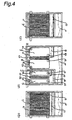
- Fig. 4 shows the evaporator E, the absorber A, the regenerator G and the condenser C arranged laterally as viewed from the front of the refrigerator.
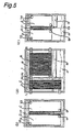
- Fig. 5 shows an absorption refrigerator which is substantially the same as that of Fig. 3, except that the plates of the regenerator G and the condenser C are vertically elongated so as to increase the areas of the plates. With this arrangement, the number of plates can be reduced, to thereby reduce the size of the absorption refrigerator as a whole.
- Fig. 6 shows an absorption refrigerator which is substantially the same as that of Fig. 2, except that the regenerator ⁇ condenser G/C, in which the plates of the regenerator G and the plates of the condenser C are alternately arranged in parallel to each other, and the absorber ⁇ condenser A/C, in which the plates of the absorber A and the plates of the evaporator E are alternately arranged in parallel to each other, are accommodated in different can bodies and connected through the communication tube 15.
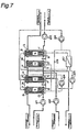
- Fig. 7 shows a system diagram indicating flow of liquid in the absorption refrigerator of the present invention.
- Fig. 7 indicates flow of liquid in the absorption refrigerator of Fig. 1.
- the absorber A and the evaporator E, and the regenerator G and the condenser C are accommodated in a can body 1a and a can body 1b, respectively.
- Cooling water is supplied from the cooling water inlet 9 into the plates of the absorber A and the plates of the condenser C and discharged from the cooling water outlet 10, by means of a cooling water pump 22.
- a heat source fluid is supplied from the heat source fluid inlet 11 into the plates of the regenerator G and discharged from the outlet 12, by means of a heat source fluid pump 23.
- cold water is supplied from the cold water inlet 13 into the plates of the evaporator E and discharged from the outlet 14, by means of a cold water pump 21.
- a diluted solution which has absorbed a cooling medium in the absorber A is circulated in such a manner as mentioned below.
- the diluted solution is supplied from the diluted solution reservoir 4 to a solution heat exchanger 27 by means of a solution circulating pump 25 and heated.
- the diluted solution is then introduced into the diluted solution supply device 3 disposed above the plates of the regenerator G and allowed to flow over the surfaces of the plates of the regenerator G which are heated by the heat source fluid.
- the cooling medium evaporates, to thereby concentrate the solution, and the concentrated solution is stored in the concentrated solution reservoir 5 disposed below the regenerator.
- the concentrated solution flows from the concentrated solution reservoir 5 through the heating side of the solution heat exchanger 27, and is introduced into the concentrated solution supply device 2 above the absorber A, by means of a solution spray pump 26.
- the solution is then allowed to flow over the surfaces of the plates of the absorber A which are cooled by the cooling water, and absorbs the cooling medium which has evaporated in the evaporator E.
- the solution is diluted and stored in the diluted solution reservoir 4. It is preferred that an inlet of the spray pump 26 and the diluted solution reservoir 4 be communicated with each other through a tube 28. This arrangement is effective for stabilizing the flow rate at the spray pump 26 and the absorber A.
- the cooling medium which has evaporated in the regenerator G condenses on the plates of the condenser C which are cooled by the cooling water, and is stored in the cooling medium reservoir 6 disposed below the condenser C.
- the stored cooling medium joins the cooling medium which is circulating through the evaporator E. and is supplied to the cooling medium supply device 7 above the evaporator E by means of a cooling medium pump 24.
- the cooling medium is allowed to flow over the plates of the evaporator E, and evaporates while removing heat from the cold water flowing within the plates.
- the evaporated cooling medium is absorbed into the concentrated solution flowing over the plates of the absorber A.
- the cooling medium which has not evaporated is recovered in the cooling medium recovery device 8 disposed below the evaporator, and returned to the cooling medium supply device 7 by means of the cooling medium pump 24.
- Fig. 8 is a schematic diagram for comparison between conventional techniques (a) and (b) and embodiments (c) and (d) of the present invention.
- Fig. 8(a) is a schematic diagram of a conventional arrangement of elements of an absorption refrigerator having a practical height (for example, 2000 mm as-mentioned above).
- Fig. 8(b) is a schematic diagram of a conventional arrangement of elements of an absorption refrigerator, in which the height of each plate is increased so as to obtain a sufficient heat transfer effect.
- Fig. 8(c) is a schematic diagram of an arrangement of elements of an absorption refrigerator according to the present invention.
- Fig. 8(d) is a schematic diagram of an arrangement of elements of an absorption refrigerator according to the present invention, in which the height of each plate is increased to a level such that the height of the refrigerator does not exceed a practical level.
- the height of the refrigerator can be maintained at a practical level while maintaining a sufficient heat transfer performance of the heat transfer plates.
Landscapes
- Engineering & Computer Science (AREA)
- Physics & Mathematics (AREA)
- Mechanical Engineering (AREA)
- Thermal Sciences (AREA)
- General Engineering & Computer Science (AREA)
- Power Engineering (AREA)
- Sorption Type Refrigeration Machines (AREA)
Abstract
There is provided an absorption refrigerator
comprising a liquid-film type plate heat exchanger
structure, which is improved in terms of installation while
maintaining the height of the refrigerator at a practical
levels.
In an absorption refrigerator utilizing a liquid-film
type plate heat exchanger for an absorber (A), an
evaporator (E), a regenerator (G) and a condenser (C), all
the absorber, the evaporator, the regenerator and the
condenser, each comprising the liquid-film type plate heat
exchanger, are arranged in a horizontal direction. The
evaporator, the absorber, the regenerator and the condenser
are accommodated in a single can body (1), and the
evaporator and the absorber, and the regenerator and the
condenser are, respectively, accommodated in different
chambers arranged in a lateral direction, which are divided
by a partition wall (16) provided in the can body. The
evaporator and the absorber, and the regenerator and the
condenser may be, respectively, accommodated in different
can bodies arranged in the lateral direction.
Description
The present invention relates to an absorption
refrigerator. More specifically, the present invention is
concerned with an absorption refrigerator in which liquid-film
type plate heat exchangers are used for an absorber,
an evaporator, a regenerator and a condenser.
An absorption refrigerator is used for various
applications, such as air conditioning, supply of cold or
hot water, etc. Generally, when an absorption refrigerator
is used for air conditioning for a building, it is
installed in a basement or on a rooftop. Therefore, it is
desired to minimize the volume of the refrigerator as well
as the installation area.
This cannot be achieved, however, in an absorption
refrigerator in which an evaporator, an absorber, a
condenser and a regenerator each have a so-called shell-and-tube
type heat exchanger structure, because such a
refrigerator has a large volume relative to a heat transfer
area. Therefore, a proposal has been made to use, as the
evaporator, the absorber, the condenser and the regenerator,
a plate type heat exchanger having a high heat transfer
efficiency relative to a volume thereof, especially a film-liquid
type plate heat exchanger.
However, differing from the shell-and-tube type heat
exchanger in which the heat transfer area can be increased
as desired by increasing the number of heat transfer tubes
or increasing the length of the heat transfer tube (while
maintaining the same height), the film-liquid type plate
heat exchanger has a problem of imparting a large height to
the refrigerator for the following reasons.
When the heat transfer area of the plate is increased
by increasing the width of the plate, it is difficult to
effect uniform flow of fluid across the entire width of the
plate, thus lowering the heat transfer efficiency of the
heat exchanger. To avoid such a lowering of the heat
transfer efficiency, it is required to elongate the plate
in a direction of flow of the fluid. Generally, the plate
is vertically oriented so as to effect flow of the fluid
efficiently in an upward or downward direction. Therefore,
the height of the plate becomes large.
Another reason is as follows. It is assumed to use a
liquid-film type plate heat exchanger in a generally
rectangular form, in which a liquid supply device (in a
rectangular form) is placed on (rectangular) liquid-film
type plates for making flow of a liquid over surfaces
of the plates. In such a liquid-film type plate heat
exchanger, the width of the liquid supply device is
required to be increased as the width of the plates is
increased, even if the capacity of the heat exchanger is
maintained constant. In other words, change in height of
the plates does not require any substantial change in the
capacity of the liquid supply device. From this point of
view, the height of the plate type heat exchanger is made
large.
Further, as compared to the shell-and-tube type heat
exchanger, the heat-exchange part of the liquid-film type
plate heat exchanger can be reduced in size as a whole.
However, in a reservoir part for an absorption solution and
a cooling medium provided below the absorber and the
evaporator, a liquid level substantially varies according
to a change in the concentration of the absorption solution.
Therefore, the height of the reservoir portion must be
large.
The height of the absorption refrigerator becomes
large mainly for the reasons mentioned above. However,
especially when the refrigerator is installed in a basement
or on a rooftop of a building for air conditioning, it is
advantageous to minimize the height of the refrigerator,
for transport and installation. A limit of a practical
height of the refrigerator is considered to be about
2,000 mm.
In a so-called double-effect absorption refrigerator
including a high-temperature regenerator, when the height
of a low-pressure can body (a can body accommodating a low-temperature
regenerator, a condenser, an absorber and an
evaporator) becomes considerably larger than that of a
high-temperature regenerator, much of the space in the
refrigerator is wasted and the refrigerator is not suitable
for practical use.
In view of the above, it is an object of the present
invention to provide a compact absorption refrigerator
using liquid-film type plate heat exchangers, in which the
height of the refrigerator can be maintained at a practical
level while the volume of the refrigerator as a whole is
reduced.
In order to achieve the above-mentioned object, the
present invention provides an absorption refrigerator
comprising an absorber, an evaporator, a regenerator and a
condenser, each having a structure of a liquid-film type
plate heat exchanger, wherein the absorber, the evaporator,
the regenerator and the condenser are arranged in a
horizontal direction.
The evaporator, the absorber, the regenerator and the
condenser may be accommodated in a single can body, and the
evaporator and the absorber, and the regenerator and the
condenser may be, respectively, accommodated in different
chambers divided by a partition wall provided in the can
body.
Specifically, each of the evaporator, the absorber,
the regenerator and the condenser may comprise an assembly
of parallel plates forming the liquid-film type plate heat
exchanger, the plates being arranged in a front-to-rear
direction relative to the front of the absorption
refrigerator, and the evaporator, the absorber, the
regenerator and the condenser may be arranged in a lateral
direction.
Each of the evaporator, the absorber, the regenerator
and the condenser may comprise an assembly of parallel
plates forming the liquid-film type plate heat exchanger,
the plates being arranged in a lateral direction relative
to the front of the absorption refrigerator; the evaporator
and the absorber may be arranged in a front-to-rear
direction relative to each other and the regenerator and
the condenser may be arranged in the front-to-rear
direction relative to each other; and the evaporator and
the absorber, and the regenerator and the condenser may be
arranged in the lateral direction.
Further, the evaporator and the absorber, and the
regenerator and the condenser may be, respectively,
accommodated in different can bodies.
Further, each of the evaporator and the absorber may
comprise an assembly of vertically oriented parallel plates
forming the liquid-film type plate heat exchanger, the
respective parallel plates of the evaporator and the
absorber being arranged in an alternate fashion in the
horizontal direction relative to each other, the evaporator
and the absorber being formed as an integral structure.
Each of the regenerator and the condenser may
comprise an assembly of vertically oriented parallel plates
forming the liquid-film type plate heat exchanger, the
respective parallel plates of the regenerator and the
condenser being arranged in an alternate fashion in the
horizontal direction relative to each other, the
regenerator and the condenser being formed as an integral
structure.
Cooling water can be supplied to the absorber and the
condenser either in parallel or in series in this order.
Next, referring to the drawings, description is made
with regard to embodiments of the present invention.
In the accompanying drawings, the present invention
is applied to a water-cooling type single-effect absorption
refrigerator. However, this does not limit the present
invention. The present invention can be applied to various
absorption refrigerators, such as a double-effect
absorption refrigerator, a water cooling/heating apparatus,
etc.
Fig. 1 shows a general arrangement of an absorption
refrigerator of the present invention. Fig. 1(a) is a
front view, Fig. 1(b) is a left side view and Fig. 1(c) is
a right side view. In Fig. 1, reference character A
denotes an absorber; E an evaporator; G a regenerator; and
C a condenser. Reference numeral 1 denotes a can body of
the absorption refrigerator; 2 a concentrated solution
supply device; 3 a diluted solution supply device; 4 a
diluted solution reservoir; 5 a concentrated solution
reservoir; 6 a cooling medium-reservoir; 7 a cooling medium
supply device; 8 a cooling medium recovery device; 9 a
cooling water inlet; 10 a cooling water outlet; 11 a heat
source fluid inlet; 12 a heat source fluid outlet; 13 a
cold water inlet; 14 a cold water outlet; 15 a
communication tube; 16 a partition wall; and 17 a droplet
separator (an eliminator).
In Fig. 1, each of the evaporator E, the absorber A,
the regenerator G and the condenser C comprises a plurality
of vertically oriented plates having the same height, which
are arranged in parallel to each other in a lateral
direction as viewed in Fig. 1(a). The evaporator E, the
absorber A, the regenerator G and the condenser C are
disposed horizontally relative to each other. They are
spaced apart from each other in a front-to-rear or lateral
direction, with the droplet separator 17 and the partition
wall 16 being disposed therebetween.
Cooling water is supplied from the cooling water
inlet 9 to the plates of the absorber A and the plates of
the condenser C in parallel. When the plate of the
absorber A and the plate of the condenser C have the same
form, the ratio of the number of plates between the
absorber and the condenser is preferably about 67:33 to
about 60:40. The supply devices 2, 3 and 7 for a cooling
medium and an absorption solution are disposed above the
plates of the absorber A, the evaporator E and the
regenerator G. The cooling medium recovery devices or
reservoirs are disposed below the plates of the evaporator
E and the condenser C.
A lower portion of the can body 1 forms the solution
reservoir 4. In operation, a solution is stored in the
reservoir 4 in a certain amount. A liquid level in the
reservoir 4 varies, in accordance with operation conditions.
However, during operation, the solution has a height such
that it does not make contact with the cooling medium
recovery device 8. When the refrigerator is stopped, the
liquid level may be increased and make contact with the
recovery device 8.
Depending on the temperature of cooling water, the
absorption solution cannot be returned to a position above
the absorber A under pressure in the regenerator G and the
condenser C. This problem is solved in this embodiment by
providing a spray pump at an outlet of a heat exchanger.
The spray pump may be provided at an outlet of the
regenerator G (an outlet of the low-temperature regenerator
in the case of a double-effect absorption refrigerator).
Fig. 2 shows a general arrangement of an absorption
refrigerator according to another embodiment of the present
invention. Fig. 2(a) is a front view. Fig. 2(b) is a left
side view and Fig. 2(c) is a right side view.
In Fig. 2, the refrigerator comprises an evaporator ·
absorber A/E integrally formed from the plates of the
evaporator E and the plates of the absorber A, which are
alternately arranged in parallel to each other in a lateral
direction as viewed in Fig. 2, and a regenerator · condenser
G/C integrally formed from the plates of the regenerator G
and the plates of the condenser C, which are alternately
arranged in parallel to each other in the lateral direction.
The evaporator · absorber A/E and the regenerator · condenser
G/C are disposed on the right side and the left side,
respectively, with the partition wall 16 being provided
therebetween. Cooling water is supplied to the plates of
the absorber A and the plates of the condenser C in
parallel.
The supply devices 2, 3 and 7 for a cooling medium
and an absorption solution are disposed above the
evaporator·absorber A/E and the regenerator·condenser G/C.
The recovery devices 6 and 8 are disposed below the plates
of the evaporator·absorber A/E and the regenerator·
condenser G/C so as to recover the cooling medium separated
from the absorption solution. The recovered cooling medium
is stored in a cooling medium tank, which is provided
separately from the can body, although such a cooling
medium tank is omitted in Fig. 2. The cooling medium tank
may be provided in the can body.
As in the case of Fig. 1, the lower portion of the
can body forms the diluted solution reservoir 4. The same
reference numerals and characters as used in Fig. 1 have
the same meanings as used in Fig. 1.
Figs. 3 to 6 show general arrangements of absorption
refrigerators according to further embodiments of the
present invention. In each of Figs. 3 to 6, (a) is a front
view, (b) is a left side view and (c) is a right side view.
Fig. 3 differs from Fig. 1 only in that the supplying
of cooling water to the absorber A and the condenser C is
conducted in series, not in parallel as conducted in the
refrigerator of Fig. 1. Cooling water supplied from the
cooling water inlet 9 first passes through the absorber A,
and is then guided to the condenser C through the
communication tube 15.
Fig. 4 shows the evaporator E, the absorber A, the
regenerator G and the condenser C arranged laterally as
viewed from the front of the refrigerator.
Fig. 5 shows an absorption refrigerator which is
substantially the same as that of Fig. 3, except that the
plates of the regenerator G and the condenser C are
vertically elongated so as to increase the areas of the
plates. With this arrangement, the number of plates can be
reduced, to thereby reduce the size of the absorption
refrigerator as a whole.
Fig. 6 shows an absorption refrigerator which is
substantially the same as that of Fig. 2, except that the
regenerator · condenser G/C, in which the plates of the
regenerator G and the plates of the condenser C are
alternately arranged in parallel to each other, and the
absorber · condenser A/C, in which the plates of the
absorber A and the plates of the evaporator E are
alternately arranged in parallel to each other, are
accommodated in different can bodies and connected through
the communication tube 15.
Fig. 7 shows a system diagram indicating flow of
liquid in the absorption refrigerator of the present
invention.
Fig. 7 indicates flow of liquid in the absorption
refrigerator of Fig. 1.
The absorber A and the evaporator E, and the
regenerator G and the condenser C are accommodated in a can
body 1a and a can body 1b, respectively. Cooling water is
supplied from the cooling water inlet 9 into the plates of
the absorber A and the plates of the condenser C and
discharged from the cooling water outlet 10, by means of a
cooling water pump 22. A heat source fluid is supplied
from the heat source fluid inlet 11 into the plates of the
regenerator G and discharged from the outlet 12, by means
of a heat source fluid pump 23. Further, cold water is
supplied from the cold water inlet 13 into the plates of
the evaporator E and discharged from the outlet 14, by
means of a cold water pump 21.
A diluted solution which has absorbed a cooling
medium in the absorber A is circulated in such a manner as
mentioned below. The diluted solution is supplied from the
diluted solution reservoir 4 to a solution heat exchanger
27 by means of a solution circulating pump 25 and heated.
The diluted solution is then introduced into the diluted
solution supply device 3 disposed above the plates of the
regenerator G and allowed to flow over the surfaces of the
plates of the regenerator G which are heated by the heat
source fluid. The cooling medium evaporates, to thereby
concentrate the solution, and the concentrated solution is
stored in the concentrated solution reservoir 5 disposed
below the regenerator. The concentrated solution flows
from the concentrated solution reservoir 5 through the
heating side of the solution heat exchanger 27, and is
introduced into the concentrated solution supply device 2
above the absorber A, by means of a solution spray pump 26.
The solution is then allowed to flow over the surfaces of
the plates of the absorber A which are cooled by the
cooling water, and absorbs the cooling medium which has
evaporated in the evaporator E. Thus, the solution is
diluted and stored in the diluted solution reservoir 4. It
is preferred that an inlet of the spray pump 26 and the
diluted solution reservoir 4 be communicated with each
other through a tube 28. This arrangement is effective for
stabilizing the flow rate at the spray pump 26 and the
absorber A.
On the other hand, the cooling medium which has
evaporated in the regenerator G condenses on the plates of
the condenser C which are cooled by the cooling water, and
is stored in the cooling medium reservoir 6 disposed below
the condenser C. The stored cooling medium joins the
cooling medium which is circulating through the evaporator
E. and is supplied to the cooling medium supply device 7
above the evaporator E by means of a cooling medium pump 24.
The cooling medium is allowed to flow over the plates of
the evaporator E, and evaporates while removing heat from
the cold water flowing within the plates. The evaporated
cooling medium is absorbed into the concentrated solution
flowing over the plates of the absorber A.
The cooling medium which has not evaporated is
recovered in the cooling medium recovery device 8 disposed
below the evaporator, and returned to the cooling medium
supply device 7 by means of the cooling medium pump 24.
Referring to Figs. 8(a) to 8(d) as schematic diagrams,
an effect of the present invention is explained below.
Fig. 8 is a schematic diagram for comparison between
conventional techniques (a) and (b) and embodiments (c) and
(d) of the present invention. Fig. 8(a) is a schematic
diagram of a conventional arrangement of elements of an
absorption refrigerator having a practical height (for
example, 2000 mm as-mentioned above). Fig. 8(b) is a
schematic diagram of a conventional arrangement of elements
of an absorption refrigerator, in which the height of each
plate is increased so as to obtain a sufficient heat
transfer effect. Fig. 8(c) is a schematic diagram of an
arrangement of elements of an absorption refrigerator
according to the present invention. Fig. 8(d) is a
schematic diagram of an arrangement of elements of an
absorption refrigerator according to the present invention,
in which the height of each plate is increased to a level
such that the height of the refrigerator does not exceed a
practical level.
In Fig. 8(a), the heat transfer plates of the
regenerator and the condenser become flat relative to a
lateral direction, and dimensions of the plate are not
practical in terms of heat transfer characteristics and
from the viewpoint of an effective heat transfer area.
When the dimensions of the plate are made practical as
shown in Fig. 8(b), the height of the absorption
refrigerator is impractical.
In Fig. 8(c), the height of the refrigerator can be
maintained at a practical level while maintaining a
sufficient heat transfer performance of the heat transfer
plates.
In Fig. 8(d), while maintaining the height of the
refrigerator at a practical level, the heat transfer area
is increased by elongating the heat transfer plates in a
vertical direction as compared to the plates in Fig. 8(c).
Consequently, the number of plates is decreased, to thereby
reduce the size of the refrigerator as a whole. Further,
as mentioned above, when the total area of the refrigerator
including the liquid supply devices is the same, the heat
transfer efficiency is higher in the refrigerator
comprising heat transfer plates in a vertically elongated
form. Therefore, the heat transfer performance can be
increased by the arrangement of Fig. 8(d).
Claims (10)
- An absorption refrigerator comprising an absorber, an evaporator, a regenerator and a condenser, each having a structure of a liquid-film type plate heat exchanger, wherein the absorber, the evaporator, the regenerator and the condenser are arranged in a horizontal direction.
- The absorption refrigerator according to claim 1, wherein the evaporator, the absorber, the regenerator and the condenser are accommodated in a single can body, and the evaporator and the absorber, and the regenerator and the condenser are, respectively, accommodated in different chambers divided by a partition wall provided in the can body.
- The absorption refrigerator according to claim 1 or 2, wherein each of the evaporator, the absorber, the regenerator and the condenser comprises an assembly of parallel plates forming the liquid-film type plate heat exchanger, the plates being arranged in a front-to-rear direction relative to the front of the absorption refrigerator, and wherein the evaporator, the absorber, the regenerator and the condenser are arranged in a lateral direction.
- The absorption refrigerator according to claim 1 or 2, wherein each of the evaporator, the absorber, the regenerator and the condenser comprises an assembly of parallel plates forming the liquid-film type plate heat exchanger, the plates being arranged in a lateral direction relative to the front of the absorption refrigerator, wherein the evaporator and the absorber are arranged in a front-to-rear direction relative to each other and the regenerator and the condenser are arranged in the front-to-rear direction relative to each other, and wherein the evaporator and the absorber, and the regenerator and the condenser are arranged in the lateral direction.
- The absorption refrigerator according to claim 1, wherein the evaporator and the absorber, and the regenerator and the condenser are, respectively, accommodated in different can bodies.
- The absorption refrigerator according to any one of claims 1, 2 and 5, wherein each of the evaporator and the absorber comprises an assembly of vertically oriented parallel plates forming the liquid-film type plate heat exchanger, the respective parallel plates of the evaporator and the absorber being arranged in an alternate fashion in the horizontal direction relative to each other, the evaporator and the absorber being formed as an integral structure.
- The absorption refrigerator according to any one of claims 1, 2 and 5, wherein each of the regenerator and the condenser comprises an assembly of vertically oriented parallel plates forming the liquid-film type plate heat exchanger, the respective parallel plates of the regenerator and the condenser being arranged in an alternate fashion in the horizontal direction relative to each other, the regenerator and the condenser being formed as an integral structure.
- The absorption refrigerator according to claim 6, wherein each of the regenerator and the condenser comprises an assembly of vertically oriented parallel plates forming the liquid-film type plate heat exchanger, the respective parallel plates of the regenerator and the condenser being arranged in an alternate fashion in the horizontal direction relative to each other, the regenerator and the condenser being formed as an integral structure.
- The absorption refrigerator according to any one of claims 1, 2 and 5, wherein cooling water is supplied to the condenser and the absorber in parallel.
- The absorption refrigerator according to any one of claims 1, 2 and 5, wherein cooling water is supplied to the absorber and the condenser in series in this order.
Applications Claiming Priority (3)
| Application Number | Priority Date | Filing Date | Title |
|---|---|---|---|
| JP33166299A JP3932241B2 (en) | 1999-11-22 | 1999-11-22 | Absorption refrigerator |
| JP33166299 | 1999-11-22 | ||
| PCT/JP2000/008205 WO2001038802A1 (en) | 1999-11-22 | 2000-11-21 | Absorption refrigerating machine |
Publications (2)
| Publication Number | Publication Date |
|---|---|
| EP1233239A1 true EP1233239A1 (en) | 2002-08-21 |
| EP1233239A4 EP1233239A4 (en) | 2009-12-02 |
Family
ID=18246186
Family Applications (1)
| Application Number | Title | Priority Date | Filing Date |
|---|---|---|---|
| EP00976395A Withdrawn EP1233239A4 (en) | 1999-11-22 | 2000-11-21 | Absorption refrigerating machine |
Country Status (5)
| Country | Link |
|---|---|
| US (1) | US6564572B1 (en) |
| EP (1) | EP1233239A4 (en) |
| JP (1) | JP3932241B2 (en) |
| CN (1) | CN1295465C (en) |
| WO (1) | WO2001038802A1 (en) |
Cited By (4)
| Publication number | Priority date | Publication date | Assignee | Title |
|---|---|---|---|---|
| FR2871221A1 (en) * | 2004-06-02 | 2005-12-09 | Peugeot Citroen Automobiles Sa | DEVICE FOR EXCHANGE AND HEAT TRANSFER, IN PARTICULAR FOR A MOTOR VEHICLE |
| CN1300542C (en) * | 2004-05-13 | 2007-02-14 | 上海交通大学 | Waste heat driven composite alternating heat pipe generator |
| EP2762800A1 (en) * | 2013-02-01 | 2014-08-06 | Basf Se | Absorption system for heating or cooling a carrier medium |
| DE202019106674U1 (en) * | 2019-11-29 | 2021-03-02 | Hochschule für angewandte Wissenschaften München | Plate apparatus for mass and heat transfer in sorption heat pumps with separation of liquid and vapor flow |
Families Citing this family (19)
| Publication number | Priority date | Publication date | Assignee | Title |
|---|---|---|---|---|
| JP2006097927A (en) * | 2004-09-28 | 2006-04-13 | Tokyo Roki Co Ltd | Heat exchanger for internal combustion engine |
| FR2900721B1 (en) * | 2006-05-02 | 2008-08-29 | Peugeot Citroen Automobiles Sa | ABSORPTION COOLING DEVICE AND ASSOCIATED MOTOR VEHICLE. |
| IL177020A0 (en) | 2006-07-23 | 2006-12-10 | Totec Ltd Top Technologies | Absorption cooling system |
| IL177021A0 (en) * | 2006-07-23 | 2006-12-10 | Totec Ltd Top Technologies | Working fluids for an absorption cooling system |
| US20100089091A1 (en) * | 2007-02-16 | 2010-04-15 | Hidetoshi Kaneo | Absorption refrigerating apparatus |
| CN102112837B (en) * | 2008-07-31 | 2013-05-08 | 佐治亚科技研究公司 | Micro heat transfer system or heat and mass transfer system |
| JP5168102B2 (en) * | 2008-11-21 | 2013-03-21 | ダイキン工業株式会社 | Absorption refrigeration system |
| JP6324129B2 (en) * | 2014-03-17 | 2018-05-16 | 大阪瓦斯株式会社 | Absorption refrigerator |
| CN106802030B (en) * | 2015-11-26 | 2023-08-01 | 四川捷元科技有限公司 | Refrigerant evaporator without circulating pump for absorption refrigeration unit |
| CN106802031B (en) * | 2015-11-26 | 2018-12-25 | 四川捷元科技有限公司 | Absorption refrigeration unit inclined-plane water conservancy diversion condenser |
| CN106802015B (en) * | 2015-11-26 | 2023-08-01 | 四川捷元科技有限公司 | Absorption refrigeration unit throttling device |
| CN106802014A (en) * | 2015-11-26 | 2017-06-06 | 四川捷元科技有限公司 | The built-in solution heat exchanger of absorption refrigeration unit |
| CN106802013B (en) * | 2015-11-26 | 2023-04-21 | 四川捷元科技有限公司 | Unit Combined Refrigeration Matrix |
| CN106802034A (en) * | 2015-11-26 | 2017-06-06 | 四川捷元科技有限公司 | Absorption refrigeration unit liquor box |
| CN106802018B (en) * | 2015-11-26 | 2023-04-21 | 四川捷元科技有限公司 | absorption refrigeration unit |
| US11123682B2 (en) * | 2017-12-14 | 2021-09-21 | University Of Florida Research Foundation, Incorporated | Liquid desiccant based dehumidification and cooling system |
| CN112236036A (en) * | 2018-05-20 | 2021-01-15 | 阿贝亚技术有限责任公司 | cryogenic storage unit |
| DE102019132955B4 (en) * | 2019-12-04 | 2022-03-31 | Hanon Systems | Heat exchanger with integrated dryer and plate for a plate heat exchanger |
| JP7439522B2 (en) * | 2020-01-14 | 2024-02-28 | 株式会社アイシン | Automotive absorption heat pump device |
Family Cites Families (14)
| Publication number | Priority date | Publication date | Assignee | Title |
|---|---|---|---|---|
| US2240178A (en) * | 1940-04-04 | 1941-04-29 | Hoover Co | Absorption refrigeration |
| US2444694A (en) * | 1942-11-16 | 1948-07-06 | Hoover Co | Absorption type portable air conditioning unit |
| NL8304112A (en) * | 1983-05-27 | 1984-12-17 | Fdo Techn Adviseurs | SORTAGE HEAT PUMP CONSTRUCTION. |
| JPH0694968B2 (en) * | 1986-01-28 | 1994-11-24 | 西淀空調機株式会社 | Adsorption refrigerator |
| US5205137A (en) * | 1990-09-05 | 1993-04-27 | Hitachi, Ltd. | Absorption air conditioner |
| JP3208161B2 (en) * | 1991-10-31 | 2001-09-10 | 大阪瓦斯株式会社 | Absorption / evaporator |
| JP3461857B2 (en) * | 1993-03-09 | 2003-10-27 | 川重冷熱工業株式会社 | High-temperature regenerator integrated with high-temperature regenerator Low-temperature regenerator using exhaust gas |
| JP3031232B2 (en) * | 1996-03-04 | 2000-04-10 | 松下電器産業株式会社 | Stacked heat exchanger for absorption heat pump |
| JP3712775B2 (en) * | 1996-04-17 | 2005-11-02 | 大阪瓦斯株式会社 | Plate evaporator / absorber for absorption refrigerator |
| JP3717272B2 (en) * | 1997-04-17 | 2005-11-16 | 大阪瓦斯株式会社 | Evaporators, absorbers and condensers used in absorption refrigerators, and absorption refrigerators |
| JPH10300260A (en) * | 1997-04-24 | 1998-11-13 | Hitachi Ltd | Absorption chiller / heater |
| JPH11218364A (en) * | 1998-02-02 | 1999-08-10 | Daikin Ind Ltd | Heat transfer device |
| JP3591356B2 (en) * | 1999-02-03 | 2004-11-17 | 株式会社日立製作所 | Absorption refrigerator and method of manufacturing the same |
| JP2000258084A (en) | 1999-03-04 | 2000-09-22 | Ebara Corp | Plate type heat exchanger |
-
1999
- 1999-11-22 JP JP33166299A patent/JP3932241B2/en not_active Expired - Fee Related
-
2000
- 2000-11-21 US US10/129,964 patent/US6564572B1/en not_active Expired - Fee Related
- 2000-11-21 CN CNB008186243A patent/CN1295465C/en not_active Expired - Fee Related
- 2000-11-21 EP EP00976395A patent/EP1233239A4/en not_active Withdrawn
- 2000-11-21 WO PCT/JP2000/008205 patent/WO2001038802A1/en not_active Ceased
Cited By (7)
| Publication number | Priority date | Publication date | Assignee | Title |
|---|---|---|---|---|
| CN1300542C (en) * | 2004-05-13 | 2007-02-14 | 上海交通大学 | Waste heat driven composite alternating heat pipe generator |
| FR2871221A1 (en) * | 2004-06-02 | 2005-12-09 | Peugeot Citroen Automobiles Sa | DEVICE FOR EXCHANGE AND HEAT TRANSFER, IN PARTICULAR FOR A MOTOR VEHICLE |
| WO2006000676A1 (en) * | 2004-06-02 | 2006-01-05 | Peugeot Citroen Automobiles S.A. | Heat exchange and heat transfer device, in particular for a motor vehicle |
| US7900472B2 (en) | 2004-06-02 | 2011-03-08 | Peugeot Citroen Automobiles Sa | Heat exchange and heat transfer device, in particular for a motor vehicle |
| EP2762800A1 (en) * | 2013-02-01 | 2014-08-06 | Basf Se | Absorption system for heating or cooling a carrier medium |
| DE202019106674U1 (en) * | 2019-11-29 | 2021-03-02 | Hochschule für angewandte Wissenschaften München | Plate apparatus for mass and heat transfer in sorption heat pumps with separation of liquid and vapor flow |
| DE102020131615B4 (en) | 2019-11-29 | 2022-03-03 | Hochschule für angewandte Wissenschaften München - Körperschaft des öffentlichen Rechts | Plate apparatus for mass and heat transfer in sorption heat pumps with separation of liquid and vapor flow |
Also Published As
| Publication number | Publication date |
|---|---|
| CN1295465C (en) | 2007-01-17 |
| US6564572B1 (en) | 2003-05-20 |
| EP1233239A4 (en) | 2009-12-02 |
| CN1425123A (en) | 2003-06-18 |
| WO2001038802A1 (en) | 2001-05-31 |
| JP2001153483A (en) | 2001-06-08 |
| JP3932241B2 (en) | 2007-06-20 |
Similar Documents
| Publication | Publication Date | Title |
|---|---|---|
| US6564572B1 (en) | Absorption refrigerator | |
| US20050006064A1 (en) | Method and means for miniaturization of binary-fluid heat and mass exchangers | |
| JP3445941B2 (en) | Multi-stage evaporative absorption type absorption chiller / heater and large temperature difference air conditioning system equipped with the same | |
| JP2000227262A (en) | Absorption refrigerator and method for producing the same | |
| US5704417A (en) | Perforated fin heat and mass transfer device | |
| US3316727A (en) | Absorption refrigeration systems | |
| US5542267A (en) | Absorption heating and cooling device | |
| US5463880A (en) | Absorption refrigerator | |
| CN105444467B (en) | Absorption heat pump | |
| JP4701147B2 (en) | 2-stage absorption refrigerator | |
| JP3997594B2 (en) | Air-cooled absorber | |
| KR890004392B1 (en) | Air-cooled absorption chiller | |
| JP3235414B2 (en) | Two-stage absorption refrigerator | |
| US6802364B1 (en) | Method and means for miniaturization of binary-fluid heat and mass exchangers | |
| CN210921674U (en) | Shell and tube condenser and water chilling unit | |
| JP2005207621A (en) | Dripping device | |
| JP4031684B2 (en) | Evaporator and refrigerator | |
| CN108375238B (en) | Absorption refrigerator | |
| KR100213780B1 (en) | Hot water supply system of absorption type air conditioner. | |
| JPH10205915A (en) | Absorption refrigerator | |
| JP2000241044A (en) | Absorption refrigerating machine | |
| JPH09280692A (en) | Plate type evaporating and absorbing device for absorption refrigerating machine | |
| KR100393585B1 (en) | a heat exchanger | |
| JP3852891B2 (en) | Solution heat exchanger for absorption refrigerator | |
| JP4423590B2 (en) | Dripping device |
Legal Events
| Date | Code | Title | Description |
|---|---|---|---|
| PUAI | Public reference made under article 153(3) epc to a published international application that has entered the european phase |
Free format text: ORIGINAL CODE: 0009012 |
|
| 17P | Request for examination filed |
Effective date: 20020522 |
|
| AK | Designated contracting states |
Kind code of ref document: A1 Designated state(s): DE FR IT SE |
|
| AX | Request for extension of the european patent |
Free format text: AL;LT;LV;MK;RO;SI |
|
| A4 | Supplementary search report drawn up and despatched |
Effective date: 20091029 |
|
| STAA | Information on the status of an ep patent application or granted ep patent |
Free format text: STATUS: THE APPLICATION HAS BEEN WITHDRAWN |
|
| 18W | Application withdrawn |
Effective date: 20100104 |