EP1233202B1 - Brake adjuster - Google Patents
Brake adjuster Download PDFInfo
- Publication number
- EP1233202B1 EP1233202B1 EP02250947A EP02250947A EP1233202B1 EP 1233202 B1 EP1233202 B1 EP 1233202B1 EP 02250947 A EP02250947 A EP 02250947A EP 02250947 A EP02250947 A EP 02250947A EP 1233202 B1 EP1233202 B1 EP 1233202B1
- Authority
- EP
- European Patent Office
- Prior art keywords
- brake
- adjuster according
- brake adjuster
- cam
- electrical signal
- Prior art date
- Legal status (The legal status is an assumption and is not a legal conclusion. Google has not performed a legal analysis and makes no representation as to the accuracy of the status listed.)
- Expired - Lifetime
Links
Images



Classifications
-
- F—MECHANICAL ENGINEERING; LIGHTING; HEATING; WEAPONS; BLASTING
- F16—ENGINEERING ELEMENTS AND UNITS; GENERAL MEASURES FOR PRODUCING AND MAINTAINING EFFECTIVE FUNCTIONING OF MACHINES OR INSTALLATIONS; THERMAL INSULATION IN GENERAL
- F16D—COUPLINGS FOR TRANSMITTING ROTATION; CLUTCHES; BRAKES
- F16D65/00—Parts or details
- F16D65/38—Slack adjusters
- F16D65/40—Slack adjusters mechanical
- F16D65/52—Slack adjusters mechanical self-acting in one direction for adjusting excessive play
- F16D65/56—Slack adjusters mechanical self-acting in one direction for adjusting excessive play with screw-thread and nut
- F16D65/567—Slack adjusters mechanical self-acting in one direction for adjusting excessive play with screw-thread and nut for mounting on a disc brake
-
- F—MECHANICAL ENGINEERING; LIGHTING; HEATING; WEAPONS; BLASTING
- F16—ENGINEERING ELEMENTS AND UNITS; GENERAL MEASURES FOR PRODUCING AND MAINTAINING EFFECTIVE FUNCTIONING OF MACHINES OR INSTALLATIONS; THERMAL INSULATION IN GENERAL
- F16D—COUPLINGS FOR TRANSMITTING ROTATION; CLUTCHES; BRAKES
- F16D65/00—Parts or details
- F16D65/14—Actuating mechanisms for brakes; Means for initiating operation at a predetermined position
- F16D65/16—Actuating mechanisms for brakes; Means for initiating operation at a predetermined position arranged in or on the brake
- F16D65/18—Actuating mechanisms for brakes; Means for initiating operation at a predetermined position arranged in or on the brake adapted for drawing members together, e.g. for disc brakes
- F16D65/183—Actuating mechanisms for brakes; Means for initiating operation at a predetermined position arranged in or on the brake adapted for drawing members together, e.g. for disc brakes with force-transmitting members arranged side by side acting on a spot type force-applying member
-
- F—MECHANICAL ENGINEERING; LIGHTING; HEATING; WEAPONS; BLASTING
- F16—ENGINEERING ELEMENTS AND UNITS; GENERAL MEASURES FOR PRODUCING AND MAINTAINING EFFECTIVE FUNCTIONING OF MACHINES OR INSTALLATIONS; THERMAL INSULATION IN GENERAL
- F16D—COUPLINGS FOR TRANSMITTING ROTATION; CLUTCHES; BRAKES
- F16D65/00—Parts or details
- F16D65/38—Slack adjusters
- F16D65/40—Slack adjusters mechanical
- F16D65/52—Slack adjusters mechanical self-acting in one direction for adjusting excessive play
- F16D65/56—Slack adjusters mechanical self-acting in one direction for adjusting excessive play with screw-thread and nut
-
- F—MECHANICAL ENGINEERING; LIGHTING; HEATING; WEAPONS; BLASTING
- F16—ENGINEERING ELEMENTS AND UNITS; GENERAL MEASURES FOR PRODUCING AND MAINTAINING EFFECTIVE FUNCTIONING OF MACHINES OR INSTALLATIONS; THERMAL INSULATION IN GENERAL
- F16D—COUPLINGS FOR TRANSMITTING ROTATION; CLUTCHES; BRAKES
- F16D65/00—Parts or details
- F16D65/38—Slack adjusters
- F16D65/40—Slack adjusters mechanical
- F16D65/52—Slack adjusters mechanical self-acting in one direction for adjusting excessive play
- F16D65/56—Slack adjusters mechanical self-acting in one direction for adjusting excessive play with screw-thread and nut
- F16D65/567—Slack adjusters mechanical self-acting in one direction for adjusting excessive play with screw-thread and nut for mounting on a disc brake
- F16D65/568—Slack adjusters mechanical self-acting in one direction for adjusting excessive play with screw-thread and nut for mounting on a disc brake for synchronous adjustment of actuators arranged in parallel
-
- F—MECHANICAL ENGINEERING; LIGHTING; HEATING; WEAPONS; BLASTING
- F16—ENGINEERING ELEMENTS AND UNITS; GENERAL MEASURES FOR PRODUCING AND MAINTAINING EFFECTIVE FUNCTIONING OF MACHINES OR INSTALLATIONS; THERMAL INSULATION IN GENERAL
- F16D—COUPLINGS FOR TRANSMITTING ROTATION; CLUTCHES; BRAKES
- F16D65/00—Parts or details
- F16D65/38—Slack adjusters
- F16D2065/386—Slack adjusters driven electrically
-
- F—MECHANICAL ENGINEERING; LIGHTING; HEATING; WEAPONS; BLASTING
- F16—ENGINEERING ELEMENTS AND UNITS; GENERAL MEASURES FOR PRODUCING AND MAINTAINING EFFECTIVE FUNCTIONING OF MACHINES OR INSTALLATIONS; THERMAL INSULATION IN GENERAL
- F16D—COUPLINGS FOR TRANSMITTING ROTATION; CLUTCHES; BRAKES
- F16D66/00—Arrangements for monitoring working conditions, e.g. wear, temperature
- F16D2066/003—Position, angle or speed
-
- F—MECHANICAL ENGINEERING; LIGHTING; HEATING; WEAPONS; BLASTING
- F16—ENGINEERING ELEMENTS AND UNITS; GENERAL MEASURES FOR PRODUCING AND MAINTAINING EFFECTIVE FUNCTIONING OF MACHINES OR INSTALLATIONS; THERMAL INSULATION IN GENERAL
- F16D—COUPLINGS FOR TRANSMITTING ROTATION; CLUTCHES; BRAKES
- F16D66/00—Arrangements for monitoring working conditions, e.g. wear, temperature
- F16D2066/005—Force, torque, stress or strain
-
- F—MECHANICAL ENGINEERING; LIGHTING; HEATING; WEAPONS; BLASTING
- F16—ENGINEERING ELEMENTS AND UNITS; GENERAL MEASURES FOR PRODUCING AND MAINTAINING EFFECTIVE FUNCTIONING OF MACHINES OR INSTALLATIONS; THERMAL INSULATION IN GENERAL
- F16D—COUPLINGS FOR TRANSMITTING ROTATION; CLUTCHES; BRAKES
- F16D2121/00—Type of actuator operation force
- F16D2121/14—Mechanical
-
- F—MECHANICAL ENGINEERING; LIGHTING; HEATING; WEAPONS; BLASTING
- F16—ENGINEERING ELEMENTS AND UNITS; GENERAL MEASURES FOR PRODUCING AND MAINTAINING EFFECTIVE FUNCTIONING OF MACHINES OR INSTALLATIONS; THERMAL INSULATION IN GENERAL
- F16D—COUPLINGS FOR TRANSMITTING ROTATION; CLUTCHES; BRAKES
- F16D2125/00—Components of actuators
- F16D2125/18—Mechanical mechanisms
- F16D2125/20—Mechanical mechanisms converting rotation to linear movement or vice versa
- F16D2125/22—Mechanical mechanisms converting rotation to linear movement or vice versa acting transversely to the axis of rotation
-
- F—MECHANICAL ENGINEERING; LIGHTING; HEATING; WEAPONS; BLASTING
- F16—ENGINEERING ELEMENTS AND UNITS; GENERAL MEASURES FOR PRODUCING AND MAINTAINING EFFECTIVE FUNCTIONING OF MACHINES OR INSTALLATIONS; THERMAL INSULATION IN GENERAL
- F16D—COUPLINGS FOR TRANSMITTING ROTATION; CLUTCHES; BRAKES
- F16D2125/00—Components of actuators
- F16D2125/18—Mechanical mechanisms
- F16D2125/20—Mechanical mechanisms converting rotation to linear movement or vice versa
- F16D2125/22—Mechanical mechanisms converting rotation to linear movement or vice versa acting transversely to the axis of rotation
- F16D2125/28—Cams; Levers with cams
- F16D2125/32—Cams; Levers with cams acting on one cam follower
-
- F—MECHANICAL ENGINEERING; LIGHTING; HEATING; WEAPONS; BLASTING
- F16—ENGINEERING ELEMENTS AND UNITS; GENERAL MEASURES FOR PRODUCING AND MAINTAINING EFFECTIVE FUNCTIONING OF MACHINES OR INSTALLATIONS; THERMAL INSULATION IN GENERAL
- F16D—COUPLINGS FOR TRANSMITTING ROTATION; CLUTCHES; BRAKES
- F16D2129/00—Type of operation source for auxiliary mechanisms
- F16D2129/06—Electric or magnetic
- F16D2129/10—Motors
-
- F—MECHANICAL ENGINEERING; LIGHTING; HEATING; WEAPONS; BLASTING
- F16—ENGINEERING ELEMENTS AND UNITS; GENERAL MEASURES FOR PRODUCING AND MAINTAINING EFFECTIVE FUNCTIONING OF MACHINES OR INSTALLATIONS; THERMAL INSULATION IN GENERAL
- F16D—COUPLINGS FOR TRANSMITTING ROTATION; CLUTCHES; BRAKES
- F16D2129/00—Type of operation source for auxiliary mechanisms
- F16D2129/06—Electric or magnetic
- F16D2129/12—Electrostrictive or magnetostrictive elements, e.g. piezoelectric
Definitions
- This invention relates to a brake adjuster for a heavy duty vehicle brake, and more particularly, the invention relates to a brake adjuster especially adapted for use with the pistons commonly found in heavy duty vehicle brakes.
- Disc brake assemblies typically include a disc brake caliper that houses a piston for forcing a pair of friction elements or brake pads into engagement with a rotor. As the brake pads wear, the piston must move further to force the brake pads into engagement with the rotor. Accordingly, it is desirable to incorporate a wear adjustment mechanism to take up any clearance in the brake assembly as the brake pads wear. If a brake adjustment mechanism is not used, the vehicle operator will undesirably be required to push the brake pedal an additional amount to compensate for the wear in the brake pads and may also need to provide a greater force at the brake pedal.
- JP7-190111 defining the preamble of claim 1 shows just such a hydraulically actuated brake caliper in which an adjuster device is situated between the hydraulic piston and one of the brake pads.
- JP7-144636 shows a brake arrangement in which pad clearance is taken up by a motor and brake clamping forces are applied by a piezo electric element.
- Heavy duty vehicle brake assemblies commonly include multiple pistons that are actuated by a cam that is manipulated by a pneumatic actuator.
- the heavy duty brake assemblies are relatively complicated compared to passenger vehicle brake assemblies.
- Heavy duty brake assemblies have typically incorporated mechanical brake adjusters to adjust the pistons as the brake pads wear.
- Prior art non-mechanical brake adjusters are unsuitable for heavy duty vehicle brake applications. Therefore, it is desirable to develop a non-mechanical brake adjuster suitable for the pistons commonly used in heavy duty vehicle brakes.
- the present invention provides a brake adjuster for a vehicle brake such as for heavy duty vehicle.
- the brake adjuster includes a brake module that produces an electrical signal for adjusting the vehicle brake.
- the heavy duty vehicle brake typically includes a pair of pistons each having first and second portions that are movable relative to one another.
- a friction element or brake pad is arranged proximate to the second portion and is movable from a desired position to a worn position as the brake pads wear during operation of the vehicle.
- the first and second portions are slip fit within a sleeve assembly.
- At least one adjustment member is arranged between the first and second portions.
- the adjustment member is constructed from a material which expands in response to an electrical signal, such as a magnetostrictive or a piezoelectric material.
- the adjustment member moves the second portion relative to the first portion and repositions the brake pads from the worn position to the desired position.
- the first and second portions are threaded to one another and movable rotationally relative to one another to adjust the length of the
- the first portions of the pistons include a plurality of teeth about the outer face.
- a gear is arranged between the pistons and coupled the teeth of the first portions together.
- An electric actuator has a driven member that is coupled with at least a portion of one of the pistons teeth to rotate the first and second portions relative to one another to increase the length of the piston. In this manner, the electric actuator moves the brake pad from the worn position to the desired position.
- a vehicle brake 10 is shown in Figure 1.
- the vehicle brake 10 includes a housing 12 that may be constructed from one or more portions.
- a rotor 14 is arranged near or within a portion of the housing and has brake pads 16, or friction elements, arranged on either side of the arcuate outer surfaces of the rotor 14.
- a pneumatic actuator 18, typically an air chamber, actuates a brake mechanism 30 to force the brake pads 16 into engagement with the rotor 14.
- the actuator 18 moves a push rod 20 to rotate a lever 22 about a pivot point.
- the lever 22 includes a cam 24 having a profile 25 that cooperates with the brake mechanism 30 to move the brake pads 16.
- the cam 24 is received by a bearing block 26 and a plurality of needle bearings 28 in the housing 12.
- the housing 12 is supported on a mounting member by guide pins 34 to permit the housing 12 to move relative to the rotor 14 as the brake pads 16 wear.
- Heavy duty vehicle brake assemblies typically include a pair of pistons 36 that transmit the force generated by the actuator 18 through the push rod 20 and lever 22 to the brake pads 16.
- the pistons 36 are not simply one piece, stamped cup-shaped members like those used for passenger cars, but rather the pistons 36 are relatively complex and include first 42 and second 44 portions that are moveable relative to one another. The movable portions 42, 44 enable the length of the pistons 36 to be adjusted as the brake pads 16 wear.
- the pistons 36 are received in the housing 12 by a sleeve assembly 38 that is received in a bearing 46 that is secured to the housing 12.
- a plate 48 is mounted to an end of the sleeve assembly 38 to which a brake pad 16 is attached.
- the sleeve 38 is received in the bearing 46 in a slip fit relation so that the sleeve 38 slides within the bearing 46 as the brakes are actuated.
- the first portions 42 of the pistons 36 each include an outer surface 50 with a plurality of teeth 52 extending radially outwardly.
- a gear 54 is arranged between the pistons 36 to couple the pistons together. That is, as the first portion 42 of one piston 46 rotates the gear 54 will transmit the rotation to the first portion 42 of the other piston 36.
- Blocks 43 are arranged between the first portion 42 and the profile 25 of the cam 24 so that the first portion 42 may more freely rotate relative to the cam 24 during actuation of the brakes.
- a return assembly 60 is used to retract the pistons 36.
- the return assembly 60 includes a plate 62 adjacent to the plurality of teeth 52.
- a return spring 64 is arranged between a portion of the housing 12 and the plate 62. The return spring 64 applies a force opposite the actuation force to the plate 62 and into the first portions 42 of the pistons 36.
- a mechanical brake adjustment device was used to rotate the first portions 42 of the pistons 36 in response to a cam mounted pin.
- the present invention utilizes an adjustment member 68 arranged in a cavity defined by the first 42 and second 44 portions. Due to friction and other forces within the brake assembly, a force of 500 N is typically required to adjust the first 42 and second 44 portions relative to one another Moreover, each of the pistons is subjected to a compressive force of approximately 150 kN during actuation of the brakes. Accordingly, it is preferable for the adjustment member 68 to provide an adjustment force of approximately 500 N in addition to being capable of withstanding a compressive force of approximately 150 kN.
- the adjustment member 68 is a magnetostrictive actuator.
- magnetostrictive actuators are available from such companies as Etrema Products, Inc.
- the magnetostrictive actuators include a magnetostrictive rod 72 adjacent to a magnetic coil 74.
- the magnetostrictive material of the rod 72 expands in response to a magnetic field generated in the magnetic coil 74.
- magnetostrictive actuators have the benefit of providing a feedback signal as the load on the magnetostrictive rod 72 changes by causing a change in the magnetic field produced by the magnetic coil 74.
- an electrical signal is produced by a control module 76 to energize the magnetic coil 74 and produce a magnetic field to expand the magnetoelectric rod 72 to move first 42 and second 44 portions away from one another.
- the adjustment member 68 moves the worn brake pad 16 from a worn position W to a desired position P to take up undesirable clearance between the brake pads 16 and the rotor 14.
- Undesirable clearance between the brake pad 16 and the rotor 14 necessitates a longer brake pedal stroke by the operator and potentially a greater input force by the operator to produce the same brake clamping force for brake pads 16 that are in a desired position.
- the adjustment member 68 also has the additional benefit of obviating the need for any load or stroke sensors thereby simplifying the operation of the brake adjuster.
- the adjustment member 68' may include one or more piezoelectric elements or discs arranged in the cavity defined by the first 42 and second 44 portions. Similar to the magnetostrictive material described above, the piezoelectric elements 78 expand in response to an electrical signal received by the adjustment 68' generated from the control module 76.
- an electrical actuator 82 is received in the housing 12.
- the electric actuator 82 includes a drive member 84 including a plurality of teeth.
- the teeth of the drive member 84 mesh with the plurality of teeth 52 on one of the first portions 42 on a piston 36.
- the control module 76 produces an electrical signal to actuate the electric actuator 82
- the drive member 84 rotatingly drives one of the first portions 42 of a piston 36 and drives the other first portion 42 of the other piston 36 through gear 64. In this manner, the pistons 36 may be lengthened or shortened.
- the electric actuator 82 may be actuated in response to any number of inputs.
- the electric actuator 82 may be actuated in response to a pin 86 extending from cam 24, which has been used for the prior art mechanical brake adjusters.
- the cam must rotate about its pivot an increased amount to move the brake pad 16 the increased distance to rotor 14.
- the control module 76 may produce an electrical signal to actuate the electric actuator 82 to take up the undesired clearance between the brake pads 16 and the rotor 14.
- the brake adjusters of this embodiment may be actuated at any time and controlled in any suitable manner.
- the vehicle brake assembly may include a stroke sensor 90 and a load sensor 92 (see figure 1).
- the stroke sensor 90 and load sensor 92 may be arranged along any suitable component at the brake assembly 10 to measure movement of the brake components that move the piston 36 and the braking force generated within the brake assembly 10.
- the sensors 90 and 92 are connected to the control module 76.
- the brake adjuster may be actuated when a lower brake clamping load is detected by the load sensor 92 at the particular stroke position.
- the lower brake clamping load is indicative of worm brake pads 16.
- the electric actuator 94 may be arranged between the pistons 36 and coaxial with the return assembly 60 to conserve space.
- the drive member of the electric actuator 94 may be the gear 54.
- the first portions 42 of the pistons 36 are both directly driven by the electric actuator 94.
- An additional feature of this embodiment may include a rotational position sensor 96 for detecting the number of rotations of the electric actuator 94 so that it may be determined how much the brake pads 16 have been adjusted to compensate for wear. This information may be used in conjunction with other brake or vehicle control systems to provide better control and maintenance of the vehicle.
Landscapes
- Engineering & Computer Science (AREA)
- General Engineering & Computer Science (AREA)
- Mechanical Engineering (AREA)
- Braking Arrangements (AREA)
Description
- This invention relates to a brake adjuster for a heavy duty vehicle brake, and more particularly, the invention relates to a brake adjuster especially adapted for use with the pistons commonly found in heavy duty vehicle brakes.
- Disc brake assemblies typically include a disc brake caliper that houses a piston for forcing a pair of friction elements or brake pads into engagement with a rotor. As the brake pads wear, the piston must move further to force the brake pads into engagement with the rotor. Accordingly, it is desirable to incorporate a wear adjustment mechanism to take up any clearance in the brake assembly as the brake pads wear. If a brake adjustment mechanism is not used, the vehicle operator will undesirably be required to push the brake pedal an additional amount to compensate for the wear in the brake pads and may also need to provide a greater force at the brake pedal.
- Passenger vehicles typically use hydraulic brake cylinders that actuate a single hydraulic piston at each brake caliper. Because passenger vehicles have a relatively low vehicle weight the brake assemblies and brake adjustment mechanisms are relatively simple. JP7-190111 defining the preamble of claim 1 shows just such a hydraulically actuated brake caliper in which an adjuster device is situated between the hydraulic piston and one of the brake pads. JP7-144636 shows a brake arrangement in which pad clearance is taken up by a motor and brake clamping forces are applied by a piezo electric element.
- Heavy duty vehicle brake assemblies commonly include multiple pistons that are actuated by a cam that is manipulated by a pneumatic actuator. The heavy duty brake assemblies are relatively complicated compared to passenger vehicle brake assemblies. Heavy duty brake assemblies have typically incorporated mechanical brake adjusters to adjust the pistons as the brake pads wear. Prior art non-mechanical brake adjusters are unsuitable for heavy duty vehicle brake applications. Therefore, it is desirable to develop a non-mechanical brake adjuster suitable for the pistons commonly used in heavy duty vehicle brakes.
- The present invention provides a brake adjuster for a vehicle brake such as for heavy duty vehicle. The brake adjuster includes a brake module that produces an electrical signal for adjusting the vehicle brake. The heavy duty vehicle brake typically includes a pair of pistons each having first and second portions that are movable relative to one another. A friction element or brake pad is arranged proximate to the second portion and is movable from a desired position to a worn position as the brake pads wear during operation of the vehicle. In one embodiment of the present invention, the first and second portions are slip fit within a sleeve assembly. At least one adjustment member is arranged between the first and second portions. The adjustment member is constructed from a material which expands in response to an electrical signal, such as a magnetostrictive or a piezoelectric material. The adjustment member moves the second portion relative to the first portion and repositions the brake pads from the worn position to the desired position. In another embodiment of the present invention, the first and second portions are threaded to one another and movable rotationally relative to one another to adjust the length of the The first portions of the pistons include a plurality of teeth about the outer face. A gear is arranged between the pistons and coupled the teeth of the first portions together. An electric actuator has a driven member that is coupled with at least a portion of one of the pistons teeth to rotate the first and second portions relative to one another to increase the length of the piston. In this manner, the electric actuator moves the brake pad from the worn position to the desired position.
According, the above embodiments of the present invention provide a brake adjuster suitable for the pistons commonly used in heavy duty vehicle brakes - Other advantages of the present invention can be understood by reference to the following detailed description when considered in connection with the accompanying drawings wherein:
- Figure 1 is a cross-sectional end view of a vehicle brake assembly of the present invention;
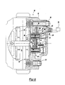
- Figure 2 is a cross-sectional top elevational view of one embodiment of the present invention;
- Figure 3A is a first adjustment member for use with the brake assembly of Figure 2;
- Figure 3B is a second adjustment member for use with the brake assembly of Figure 2;
- Figure 4 is a cross-sectional top elevational view of another brake adjuster of an alternative embodiment; and
- Figure 5 is a cross-sectional top elevational view of yet another brake adjuster of an alternative embodiment.
- A
vehicle brake 10 is shown in Figure 1. Thevehicle brake 10 includes ahousing 12 that may be constructed from one or more portions. Arotor 14 is arranged near or within a portion of the housing and hasbrake pads 16, or friction elements, arranged on either side of the arcuate outer surfaces of therotor 14. Apneumatic actuator 18, typically an air chamber, actuates abrake mechanism 30 to force thebrake pads 16 into engagement with therotor 14. Theactuator 18 moves apush rod 20 to rotate alever 22 about a pivot point. Thelever 22 includes acam 24 having aprofile 25 that cooperates with thebrake mechanism 30 to move thebrake pads 16. Thecam 24 is received by a bearing block 26 and a plurality ofneedle bearings 28 in thehousing 12. - As is known in the art, the
housing 12 is supported on a mounting member byguide pins 34 to permit thehousing 12 to move relative to therotor 14 as thebrake pads 16 wear. Heavy duty vehicle brake assemblies typically include a pair ofpistons 36 that transmit the force generated by theactuator 18 through thepush rod 20 and lever 22 to thebrake pads 16. However, it is to be understood that any suitable number ofpistons 36 may be used. Thepistons 36 are not simply one piece, stamped cup-shaped members like those used for passenger cars, but rather thepistons 36 are relatively complex and include first 42 and second 44 portions that are moveable relative to one another. Themovable portions pistons 36 to be adjusted as thebrake pads 16 wear. For the embodiments shown in Figure 2, thepistons 36 are received in thehousing 12 by asleeve assembly 38 that is received in a bearing 46 that is secured to thehousing 12. Aplate 48 is mounted to an end of thesleeve assembly 38 to which abrake pad 16 is attached. Thesleeve 38 is received in the bearing 46 in a slip fit relation so that thesleeve 38 slides within the bearing 46 as the brakes are actuated. - The
first portions 42 of thepistons 36 each include anouter surface 50 with a plurality ofteeth 52 extending radially outwardly. Agear 54 is arranged between thepistons 36 to couple the pistons together. That is, as thefirst portion 42 of one piston 46 rotates thegear 54 will transmit the rotation to thefirst portion 42 of theother piston 36.Blocks 43 are arranged between thefirst portion 42 and theprofile 25 of thecam 24 so that thefirst portion 42 may more freely rotate relative to thecam 24 during actuation of the brakes. - After the brakes are actuated, the
brake pads 16 must be retracted to prevent thebrake pads 16 from dragging on therotor 14. To this end, areturn assembly 60 is used to retract thepistons 36. Thereturn assembly 60 includes aplate 62 adjacent to the plurality ofteeth 52. Areturn spring 64 is arranged between a portion of thehousing 12 and theplate 62. Thereturn spring 64 applies a force opposite the actuation force to theplate 62 and into thefirst portions 42 of thepistons 36. - Previously, a mechanical brake adjustment device was used to rotate the
first portions 42 of thepistons 36 in response to a cam mounted pin. The present invention, in one embodiment, utilizes anadjustment member 68 arranged in a cavity defined by the first 42 and second 44 portions. Due to friction and other forces within the brake assembly, a force of 500 N is typically required to adjust the first 42 and second 44 portions relative to one another Moreover, each of the pistons is subjected to a compressive force of approximately 150 kN during actuation of the brakes. Accordingly, it is preferable for theadjustment member 68 to provide an adjustment force of approximately 500 N in addition to being capable of withstanding a compressive force of approximately 150 kN. In one preferred embodiment theadjustment member 68 is a magnetostrictive actuator. Such magnetostrictive actuators are available from such companies as Etrema Products, Inc. The magnetostrictive actuators include amagnetostrictive rod 72 adjacent to amagnetic coil 74. The magnetostrictive material of therod 72 expands in response to a magnetic field generated in themagnetic coil 74. Additionally, magnetostrictive actuators have the benefit of providing a feedback signal as the load on themagnetostrictive rod 72 changes by causing a change in the magnetic field produced by themagnetic coil 74. - In operation, upon actuation of the brake pedal by the vehicle operator, an electrical signal is produced by a
control module 76 to energize themagnetic coil 74 and produce a magnetic field to expand themagnetoelectric rod 72 to move first 42 and second 44 portions away from one another. In this manner, theadjustment member 68 moves theworn brake pad 16 from a worn position W to a desired position P to take up undesirable clearance between thebrake pads 16 and therotor 14. Undesirable clearance between thebrake pad 16 and therotor 14 necessitates a longer brake pedal stroke by the operator and potentially a greater input force by the operator to produce the same brake clamping force forbrake pads 16 that are in a desired position. Theadjustment member 68 also has the additional benefit of obviating the need for any load or stroke sensors thereby simplifying the operation of the brake adjuster. - In a second embodiment, shown in Figure 3B, the adjustment member 68' may include one or more piezoelectric elements or discs arranged in the cavity defined by the first 42 and second 44 portions. Similar to the magnetostrictive material described above, the
piezoelectric elements 78 expand in response to an electrical signal received by the adjustment 68' generated from thecontrol module 76. - Alternative embodiments of brake adjusters are shown in Figures 4 and 5. Referring to Figure 4, an
electrical actuator 82 is received in thehousing 12. Theelectric actuator 82 includes adrive member 84 including a plurality of teeth. The teeth of thedrive member 84 mesh with the plurality ofteeth 52 on one of thefirst portions 42 on apiston 36. When thecontrol module 76 produces an electrical signal to actuate theelectric actuator 82, thedrive member 84 rotatingly drives one of thefirst portions 42 of apiston 36 and drives the otherfirst portion 42 of theother piston 36 throughgear 64. In this manner, thepistons 36 may be lengthened or shortened. - The
electric actuator 82 may be actuated in response to any number of inputs. For example, theelectric actuator 82 may be actuated in response to apin 86 extending fromcam 24, which has been used for the prior art mechanical brake adjusters. As the brake pads wear, the cam must rotate about its pivot an increased amount to move thebrake pad 16 the increased distance torotor 14. As a result, it may be desirable to include a sensor 88 adjacent to thepin 86 to sense the location of the pin. When thepin 86 reaches a point indicative of thebrake pads 16 being in a worn position W thecontrol module 76 may produce an electrical signal to actuate theelectric actuator 82 to take up the undesired clearance between thebrake pads 16 and therotor 14. However, it is to be understood that the brake adjusters of this embodiment may be actuated at any time and controlled in any suitable manner. - For example, the vehicle brake assembly may include a
stroke sensor 90 and a load sensor 92 (see figure 1). Thestroke sensor 90 andload sensor 92 may be arranged along any suitable component at thebrake assembly 10 to measure movement of the brake components that move thepiston 36 and the braking force generated within thebrake assembly 10. Thesensors control module 76. When thebrake pads 16 are in a desired position P during the application of the brakes, a particular brake clamping load will be generated at a particular brake stroke position. Accordingly, the brake adjuster may be actuated when a lower brake clamping load is detected by theload sensor 92 at the particular stroke position. The lower brake clamping load is indicative ofworm brake pads 16. - Referring to Figure 5, the
electric actuator 94 may be arranged between thepistons 36 and coaxial with thereturn assembly 60 to conserve space. The drive member of theelectric actuator 94 may be thegear 54. Unlike the embodiment shown in Figure 4, thefirst portions 42 of thepistons 36 are both directly driven by theelectric actuator 94. An additional feature of this embodiment may include arotational position sensor 96 for detecting the number of rotations of theelectric actuator 94 so that it may be determined how much thebrake pads 16 have been adjusted to compensate for wear. This information may be used in conjunction with other brake or vehicle control systems to provide better control and maintenance of the vehicle. - The invention has been described in an illustrative manner, and it is to be understood that the terminology that has been used is intended to be in the nature of words of description rather than of limitation. Obviously, many modifications and variations of the present invention are possible in light of the above teachings. It is, therefore, to be understood that within the scope of the appended claims the invention may be practiced otherwise than as specifically described.
Claims (12)
- A brake adjuster for a vehicle brake (10) comprising:a control module (76) producing an electrical signal for adjusting the vehicle brake;a piston (36) having first (42) and second (44) portions movable relative to one another;a friction element (16) proximate to said second portion and movable between a worn position (W) and a desired position (P); andat least one adjustment member (68,68') interposed between said first and second portions, characterized in that said adjustment member is constructed from a material which expands in response to an electrical signal to move said second portion relative to said first portion and reposition said friction element from said worn position to said desired position.
- The brake adjuster according to claim 1, further including a sleeve assembly (38) with said piston dispose therein, said sleeve assembly interposed between said friction element and said second portion.
- The brake adjuster according to claim 1 or 2, further including a block (43) adjacent to said first portion and a cam (24) adjacent to said block, said cam applying a braking force to said piston and said friction element.
- The brake adjuster according to any preceding claim, wherein said adjustment member comprises a magnetostrictive rod (72), and further including a magnetic coil (74) proximate to said adjustment member for creating a magnetic field in response to said electrical signal.
- The brake adjuster according to claim 4, wherein said magnetostrictive material is Terfanol-D.
- The brake adjuster according to any one of claims 1 to 5, wherein said adjustment member produces a feedback signal in response to achieving a predetermined adjustment load.
- The brake adjuster according to any one of claims 1 to 3 or claim 6 when dependant on any one of claims 1 to 3, wherein said adjustment member comprises a piezoelectric disc (78) excitable in response to said electrical signal.
- The brake adjuster according to any preceding claim, further including a block (43) proximate to said first portion and a cam (24) adjacent to said block, said cam applying a braking force to said piston and said friction element.
- The brake adjuster according to claim 8, wherein said cam includes a pin (86) extending therefrom movable with said cam during application of said braking force, and further including a sensor (88) adjacent to said pin for sensing an adjustment position of said pin corresponding to said wear position of said friction element, and said control module producing said electrical signal in response to pin reaching said adjustment position.
- The brake adjuster according to claim 8 or 9, wherein said control module produces said electrical signal at an initial actuation of said cam prior to applying said braking force.
- The brake adjuster according to any one of claims 8 to 10, further including a pushrod (20) connected to said cam for providing said braking force, a stroke sensor (90) for determining an actuation distance of said pushrod, and a load sensor (92) for determining said braking force, said control module producing said electrical signal in response to said actuation distance reaching a predetermined value at a predetermined braking force.
- The brake adjuster according to claim 11, wherein said stroke sensor is proximate to said pushrod for determining an actual actuation distance of said pushrod.
Priority Applications (1)
| Application Number | Priority Date | Filing Date | Title |
|---|---|---|---|
| EP07004424A EP1793140A3 (en) | 2001-02-19 | 2002-02-12 | Brake adjuster |
Applications Claiming Priority (2)
| Application Number | Priority Date | Filing Date | Title |
|---|---|---|---|
| US09/788,912 US6481542B2 (en) | 2001-02-19 | 2001-02-19 | Brake adjuster |
| US788912 | 2001-02-19 |
Related Child Applications (1)
| Application Number | Title | Priority Date | Filing Date |
|---|---|---|---|
| EP07004424A Division EP1793140A3 (en) | 2001-02-19 | 2002-02-12 | Brake adjuster |
Publications (3)
| Publication Number | Publication Date |
|---|---|
| EP1233202A2 EP1233202A2 (en) | 2002-08-21 |
| EP1233202A3 EP1233202A3 (en) | 2004-05-06 |
| EP1233202B1 true EP1233202B1 (en) | 2007-05-23 |
Family
ID=25145969
Family Applications (2)
| Application Number | Title | Priority Date | Filing Date |
|---|---|---|---|
| EP02250947A Expired - Lifetime EP1233202B1 (en) | 2001-02-19 | 2002-02-12 | Brake adjuster |
| EP07004424A Withdrawn EP1793140A3 (en) | 2001-02-19 | 2002-02-12 | Brake adjuster |
Family Applications After (1)
| Application Number | Title | Priority Date | Filing Date |
|---|---|---|---|
| EP07004424A Withdrawn EP1793140A3 (en) | 2001-02-19 | 2002-02-12 | Brake adjuster |
Country Status (3)
| Country | Link |
|---|---|
| US (1) | US6481542B2 (en) |
| EP (2) | EP1233202B1 (en) |
| DE (1) | DE60220199T2 (en) |
Families Citing this family (34)
| Publication number | Priority date | Publication date | Assignee | Title |
|---|---|---|---|---|
| US20060289253A1 (en) * | 2005-06-23 | 2006-12-28 | Kelsey-Hayes Company | Monoblock caliper housing for a disc brake assembly |
| US20050045434A1 (en) * | 2003-04-02 | 2005-03-03 | Franz-Helmut Holl | Vehicle brake assembly having an assembly opening and method of assembly therefor |
| US6817452B2 (en) * | 2003-04-02 | 2004-11-16 | Arvinmeritor Technology, Llc | Lever assembly having a selectable push rod receiving insert for a vehicle brake assembly and method of assembly therefor |
| US6811004B1 (en) * | 2003-05-09 | 2004-11-02 | Arvinmeritor Technology, Llc | Vehicle brake assembly having a bearing block closure and method of assembly therefor |
| US20040222051A1 (en) * | 2003-05-09 | 2004-11-11 | Mccann Denis John | Multi-component lever assembly for a vehicle brake assembly and method of assembly therefor |
| DE10325596A1 (en) * | 2003-06-05 | 2005-01-05 | Federal-Mogul Friction Products Gmbh | Cylinder stroke detection device for pneumatic disc brakes |
| US20040251092A1 (en) * | 2003-06-11 | 2004-12-16 | Kramer Dennis A. | Two stage device for applying brake pad force to a rotor with motor and expandable material |
| GB0324243D0 (en) * | 2003-10-16 | 2003-11-19 | Meritor Heavy Vehicle Braking | A control system and method for a disc brake |
| DE10356801B3 (en) * | 2003-12-04 | 2005-05-25 | Wabco Radbremsen Gmbh | Disk brake comprises a monitoring device having a measuring element that can be displaced relative to a caliper and is supported on an end surface of a pressure screw facing away from a brake disk |
| FR2870906B1 (en) * | 2004-05-27 | 2006-08-11 | Bosch Gmbh Robert | BRAKE ACTUATING DEVICE AND DISC BRAKE FOR A MOTOR VEHICLE HAVING SUCH A DEVICE |
| DE602004015613D1 (en) * | 2004-10-25 | 2008-09-18 | Meritor Heavy Vehicle Braking | Brake lever assembly for motor vehicle and method of assembly |
| US20060289251A1 (en) * | 2005-06-23 | 2006-12-28 | Kelsey-Hayes Company | Taper wear compensation of a friction pad for a disc brake assembly |
| DE102008035753A1 (en) * | 2008-07-31 | 2010-02-04 | Wabco Radbremsen Gmbh | Method for producing a caliper, machining tool for carrying out the method, brake caliper produced by the method and disc brake with such a caliper |
| US8319623B2 (en) | 2009-01-23 | 2012-11-27 | Mgm Brakes | Brake monitoring system and method |
| CA2734061C (en) | 2010-03-15 | 2018-11-20 | Nbs Innovative Solutions Ltd | Vehicle brake monitoring system and method |
| EP2582998A4 (en) | 2010-06-18 | 2017-04-19 | MGM Brakes | Electronic stroke sensor for air disc brake |
| US9855940B2 (en) | 2010-06-18 | 2018-01-02 | Indian Head Industries, Inc. | Electronic stroke sensor for air disc brake |
| US8662277B2 (en) | 2011-12-22 | 2014-03-04 | Fairfield Manufacturing Company, Inc. | Planetary gearbox with integral service brake |
| US8960380B2 (en) | 2012-01-12 | 2015-02-24 | Oil States Industries, Inc. | Liquid-cooled brake assembly with removable heat transfer insert |
| US8820490B2 (en) | 2012-03-16 | 2014-09-02 | Arvinmeritor Technology, Llc | Manual adjuster for automatic slack adjuster |
| DE102012107233A1 (en) * | 2012-08-07 | 2014-02-13 | Knorr-Bremse Systeme für Nutzfahrzeuge GmbH | Disc brake for a commercial vehicle and method for its production |
| US8910753B1 (en) * | 2013-06-11 | 2014-12-16 | Fernando De La Cerda | Customizable brake monitoring system |
| EP3540257B1 (en) * | 2013-08-15 | 2022-07-20 | Meritor Heavy Vehicle Braking Systems (UK) Limited | A method of adjusting a brake |
| CN103486163B (en) * | 2013-09-29 | 2016-06-08 | 江苏理工学院 | Vehicle Electromechanical Braking Systems Piezoelectric Brake Actuators |
| DE102013112813A1 (en) * | 2013-11-20 | 2015-05-21 | Knorr-Bremse Systeme für Nutzfahrzeuge GmbH | Sensor device and disc brake with a sensor device |
| US9429227B2 (en) | 2014-02-19 | 2016-08-30 | Fairfield Manufacturing Company, Inc. | Planetary gearbox with integral service brake |
| DE102014107401A1 (en) | 2014-05-26 | 2015-11-26 | Knorr-Bremse Systeme für Nutzfahrzeuge GmbH | Disc brake, caliper and brake pad set for a disc brake |
| EP3051163B1 (en) * | 2015-01-28 | 2019-07-24 | Meritor Heavy Vehicle Braking Systems (UK) Limited | A disc brake |
| DE102015202744B4 (en) * | 2015-02-16 | 2017-08-24 | Saf-Holland Gmbh | adjusting unit |
| CN106870603B (en) * | 2015-12-10 | 2020-01-14 | 英国美瑞特重型车制动系统有限公司 | Adjuster assembly |
| EP3179126A1 (en) * | 2015-12-10 | 2017-06-14 | Meritor Heavy Vehicle Braking Systems (UK) Limited | Adjuster assembly |
| JP6506236B2 (en) * | 2016-11-28 | 2019-04-24 | トヨタ自動車株式会社 | Electric brake control device |
| US11460083B2 (en) * | 2020-02-03 | 2022-10-04 | Haldex Brake Products Corporation | Systems and methods for sensing a brake component with an acoustic sensor |
| US11718283B2 (en) * | 2020-09-18 | 2023-08-08 | Arvinmeritor Technology, Llc | Brake assembly having a sensor |
Family Cites Families (28)
| Publication number | Priority date | Publication date | Assignee | Title |
|---|---|---|---|---|
| US3365029A (en) | 1966-02-17 | 1968-01-23 | Kelsey Hayes Co | Adjusting means for disk brakes |
| DE1920128A1 (en) | 1969-04-21 | 1970-11-05 | Lenze Kg Maschf Hans | Automatic adjustment device for two-disc or multi-disc spring-force clutches or brakes with electromagnetic release of the clutch or ventilation of the brake |
| US3998295A (en) * | 1969-08-12 | 1976-12-21 | Martin Thomas C | Brake structure and adjusting device therefor |
| DE2164134C3 (en) | 1971-12-23 | 1979-01-18 | Zahnradfabrik Friedrichshafen Ag, 7990 Friedrichshafen | Electromagnetic spring pressure brake with automatic adjustment device |
| DE2164542C3 (en) | 1971-12-24 | 1980-04-17 | Zahnradfabrik Friedrichshafen Ag, 7990 Friedrichshafen | Automatic adjustment device to compensate for the abrasion of the friction disc of an electromagnetically releasable spring pressure brake or clutch |
| US3830343A (en) | 1972-12-12 | 1974-08-20 | Goodrich Co B F | Disc brake with adjustable cam operator and thrust distributer |
| US4006669A (en) | 1975-05-19 | 1977-02-08 | The Bendix Corporation | Piston and extensible cylinder therefor |
| US4208952A (en) | 1976-12-27 | 1980-06-24 | The Bendix Corporation | Piston with extended axial travel |
| US4378863A (en) | 1979-08-30 | 1983-04-05 | Lucas Industries Limited | Automatic adjuster for hydraulic brake actuator |
| US4436186A (en) | 1981-10-02 | 1984-03-13 | The Bendix Corporation | Disc brake assembly |
| US4503950A (en) | 1983-01-27 | 1985-03-12 | Allied Corporation | Brake actuator-adjuster mechanism |
| EP0139518B1 (en) | 1983-10-19 | 1988-07-27 | LUCAS INDUSTRIES public limited company | Improvements in hydraulic actuator assemblies for vehicle brakes |
| US4757300A (en) * | 1984-05-02 | 1988-07-12 | Adam Sebalos | Brake adjustment monitoring device for automotive vehicles |
| US4966255A (en) | 1988-11-16 | 1990-10-30 | Reliance Electric Industrial Company | Automatic wear compensator for electromagnetic brake |
| FI901247A7 (en) | 1990-03-13 | 1991-09-14 | Kone Oy | ELECTROMAGNETIC BRAKE. |
| FI85907C (en) | 1990-03-13 | 1992-06-10 | Kone Oy | ELECTROMAGNETIC BROMS. |
| JPH07144636A (en) * | 1993-11-22 | 1995-06-06 | Akebono Brake Res & Dev Center Ltd | Electrically operated braking device |
| JP3773211B2 (en) * | 1993-12-27 | 2006-05-10 | 曙ブレーキ工業株式会社 | Disc brake device |
| DE59508013D1 (en) * | 1994-01-18 | 2000-04-20 | Meritor Automotive Inc | Application device for a disc brake, especially for heavy commercial vehicles |
| DE19528457C2 (en) * | 1995-08-03 | 2001-03-08 | Mannesmann Vdo Ag | Control device |
| DE19536694A1 (en) | 1995-09-30 | 1997-04-03 | Teves Gmbh Alfred | Control system for an electromotive wheel brake |
| JP3837195B2 (en) | 1996-12-26 | 2006-10-25 | 曙ブレーキ工業株式会社 | Electric brake with pad clearance adjustment mechanism and pad clearance adjustment method |
| NL1006540C2 (en) * | 1997-07-10 | 1999-01-15 | Skf Ind Trading & Dev | Electric actuator with control sensor, as well as disc brake comprising such an actuator. |
| DE19731696A1 (en) * | 1997-07-23 | 1999-02-11 | Knorr Bremse Systeme | Wear adjusting device for disc brakes and method for controlling the device |
| US6016892A (en) | 1997-08-01 | 2000-01-25 | Alliedsignal Inc. | Pinless internal automatic adjuster for brake piston |
| GB9823198D0 (en) * | 1998-10-24 | 1998-12-16 | Lucas Ind Plc | Vehicle brake having electric motor control of brake running clearance |
| DE19858764C2 (en) * | 1998-12-18 | 2000-11-02 | Siemens Ag | Electromechanical motor vehicle braking device |
| WO2002014710A2 (en) * | 2000-08-17 | 2002-02-21 | Knorr-Bremse Systeme für Nutzfahrzeuge GmbH | Disc brake comprising an adjusting device on each side of the brake disc |
-
2001
- 2001-02-19 US US09/788,912 patent/US6481542B2/en not_active Expired - Fee Related
-
2002
- 2002-02-12 DE DE60220199T patent/DE60220199T2/en not_active Expired - Fee Related
- 2002-02-12 EP EP02250947A patent/EP1233202B1/en not_active Expired - Lifetime
- 2002-02-12 EP EP07004424A patent/EP1793140A3/en not_active Withdrawn
Non-Patent Citations (1)
| Title |
|---|
| None * |
Also Published As
| Publication number | Publication date |
|---|---|
| DE60220199D1 (en) | 2007-07-05 |
| US20020112927A1 (en) | 2002-08-22 |
| DE60220199T2 (en) | 2008-01-17 |
| EP1233202A2 (en) | 2002-08-21 |
| EP1793140A2 (en) | 2007-06-06 |
| EP1793140A3 (en) | 2008-10-15 |
| US6481542B2 (en) | 2002-11-19 |
| EP1233202A3 (en) | 2004-05-06 |
Similar Documents
| Publication | Publication Date | Title |
|---|---|---|
| US6481542B2 (en) | Brake adjuster | |
| US9127735B2 (en) | Friction brake | |
| US7434669B2 (en) | Hydraulic vehicle brake | |
| US6315092B1 (en) | Electromechanically actuated disc brake | |
| EP1524449B1 (en) | A control system and method for the running clearance of a disc brake. | |
| US6293370B1 (en) | Vehicle brake having electric motor control of brake running clearance | |
| EP3269993B1 (en) | Disc brake for a commercial vehicle | |
| EP1762746B1 (en) | Brake monitoring and control system | |
| AU690362B2 (en) | A safety brake arrangement in a brake actuator | |
| EP1596089B1 (en) | A parking brake assembly | |
| US12240425B2 (en) | Compact electromechanical brake | |
| JP2013174357A (en) | Braking unit | |
| JP4210333B2 (en) | Disc brake | |
| GB2102088A (en) | Disc brakes | |
| US20250341241A1 (en) | Method for controlling an electromechanical brake | |
| JP2022532804A (en) | Electromechanical drum brake with actuator with low stiffness elastic reserve | |
| EP4069562B1 (en) | Brake actuator, in particular electromechanical brake actuator of a commercial vehicle | |
| KR20060135743A (en) | Hydraulic vehicle-brake | |
| JP2005291337A (en) | Disc brake | |
| GB2310015A (en) | Vehicle brake assemblies | |
| EP3336374B1 (en) | Mechanical brake | |
| US20010030089A1 (en) | Dragless brake caliper | |
| GB2369661A (en) | Piezoelectric actuator for vehicle brakes | |
| WO2010112078A1 (en) | Piston retraction arrangement | |
| KR20040053920A (en) | brake apparatus for automobile |
Legal Events
| Date | Code | Title | Description |
|---|---|---|---|
| PUAI | Public reference made under article 153(3) epc to a published international application that has entered the european phase |
Free format text: ORIGINAL CODE: 0009012 |
|
| AK | Designated contracting states |
Kind code of ref document: A2 Designated state(s): AT BE CH CY DE DK ES FI FR GB GR IE IT LI LU MC NL PT SE TR |
|
| AX | Request for extension of the european patent |
Free format text: AL;LT;LV;MK;RO;SI |
|
| PUAL | Search report despatched |
Free format text: ORIGINAL CODE: 0009013 |
|
| AK | Designated contracting states |
Kind code of ref document: A3 Designated state(s): AT BE CH CY DE DK ES FI FR GB GR IE IT LI LU MC NL PT SE TR |
|
| AX | Request for extension of the european patent |
Extension state: AL LT LV MK RO SI |
|
| 17P | Request for examination filed |
Effective date: 20040528 |
|
| AKX | Designation fees paid |
Designated state(s): DE FR GB IT SE |
|
| GRAP | Despatch of communication of intention to grant a patent |
Free format text: ORIGINAL CODE: EPIDOSNIGR1 |
|
| GRAS | Grant fee paid |
Free format text: ORIGINAL CODE: EPIDOSNIGR3 |
|
| GRAA | (expected) grant |
Free format text: ORIGINAL CODE: 0009210 |
|
| AK | Designated contracting states |
Kind code of ref document: B1 Designated state(s): DE FR GB IT SE |
|
| REG | Reference to a national code |
Ref country code: GB Ref legal event code: FG4D |
|
| REF | Corresponds to: |
Ref document number: 60220199 Country of ref document: DE Date of ref document: 20070705 Kind code of ref document: P |
|
| REG | Reference to a national code |
Ref country code: SE Ref legal event code: TRGR |
|
| ET | Fr: translation filed | ||
| PLBE | No opposition filed within time limit |
Free format text: ORIGINAL CODE: 0009261 |
|
| STAA | Information on the status of an ep patent application or granted ep patent |
Free format text: STATUS: NO OPPOSITION FILED WITHIN TIME LIMIT |
|
| 26N | No opposition filed |
Effective date: 20080226 |
|
| EUG | Se: european patent has lapsed | ||
| GBPC | Gb: european patent ceased through non-payment of renewal fee |
Effective date: 20080212 |
|
| REG | Reference to a national code |
Ref country code: FR Ref legal event code: ST Effective date: 20081031 |
|
| PG25 | Lapsed in a contracting state [announced via postgrant information from national office to epo] |
Ref country code: SE Free format text: LAPSE BECAUSE OF NON-PAYMENT OF DUE FEES Effective date: 20080213 Ref country code: DE Free format text: LAPSE BECAUSE OF NON-PAYMENT OF DUE FEES Effective date: 20080902 |
|
| PG25 | Lapsed in a contracting state [announced via postgrant information from national office to epo] |
Ref country code: FR Free format text: LAPSE BECAUSE OF NON-PAYMENT OF DUE FEES Effective date: 20080229 |
|
| PG25 | Lapsed in a contracting state [announced via postgrant information from national office to epo] |
Ref country code: GB Free format text: LAPSE BECAUSE OF NON-PAYMENT OF DUE FEES Effective date: 20080212 |
|
| PG25 | Lapsed in a contracting state [announced via postgrant information from national office to epo] |
Ref country code: IT Free format text: LAPSE BECAUSE OF NON-PAYMENT OF DUE FEES Effective date: 20080212 |