EP1233104A2 - Method and device for white water drainage - Google Patents
Method and device for white water drainage Download PDFInfo
- Publication number
- EP1233104A2 EP1233104A2 EP02000918A EP02000918A EP1233104A2 EP 1233104 A2 EP1233104 A2 EP 1233104A2 EP 02000918 A EP02000918 A EP 02000918A EP 02000918 A EP02000918 A EP 02000918A EP 1233104 A2 EP1233104 A2 EP 1233104A2
- Authority
- EP
- European Patent Office
- Prior art keywords
- collecting basin
- white water
- channel
- area
- water level
- Prior art date
- Legal status (The legal status is an assumption and is not a legal conclusion. Google has not performed a legal analysis and makes no representation as to the accuracy of the status listed.)
- Ceased
Links
Images
Classifications
-
- D—TEXTILES; PAPER
- D21—PAPER-MAKING; PRODUCTION OF CELLULOSE
- D21F—PAPER-MAKING MACHINES; METHODS OF PRODUCING PAPER THEREON
- D21F1/00—Wet end of machines for making continuous webs of paper
- D21F1/66—Pulp catching, de-watering, or recovering; Re-use of pulp-water
-
- Y—GENERAL TAGGING OF NEW TECHNOLOGICAL DEVELOPMENTS; GENERAL TAGGING OF CROSS-SECTIONAL TECHNOLOGIES SPANNING OVER SEVERAL SECTIONS OF THE IPC; TECHNICAL SUBJECTS COVERED BY FORMER USPC CROSS-REFERENCE ART COLLECTIONS [XRACs] AND DIGESTS
- Y10—TECHNICAL SUBJECTS COVERED BY FORMER USPC
- Y10S—TECHNICAL SUBJECTS COVERED BY FORMER USPC CROSS-REFERENCE ART COLLECTIONS [XRACs] AND DIGESTS
- Y10S162/00—Paper making and fiber liberation
- Y10S162/07—Water collectors, e.g. save-alls
Definitions
- the invention relates to a method and a device for removing the within the loop of a circulating dewatering screen of a former a paper machine of white water.
- Methods and devices of this type are, for example, from EP 0 258 918 B1, US 4,895,623, AT-PS 293,855 and US 2,893,486.
- the aim of the invention is to provide an improved method and an improved device to create the type mentioned, in which the aforementioned Disadvantages are eliminated.
- this object is achieved by a method for removal inside the loop of a circulating dewatering screen of a former, in particular a twin wire former, a paper machine White water, in which the white water is arranged by a within the loop Collection basin collected, the collected white water by suction the area above the collecting basin still within the sieve loop separated from the air and the white water over at least one itself adjoining the reservoir, below the water level Canal is removed from the collection basin.
- the amount of white water generated is already within the wire loop or in the sieve ship so far from the air that they are completely Pipeline filled with white water discharged from the machine area can be.
- the space previously required outside the machine frame for gutter laying and the installation of separators significantly reduced.
- the possibilities for standard arrangements are correspondingly created because of the risk of a possible collision with the building is reduced to a minimum.
- the previously required separators next to the paper machine can be omitted.
- there is a simpler stool since no breakthroughs in the stool are required for white water drainage are.
- the largest possible collection basin is used.
- the collecting basin expediently extends to the two sides of the chair on the leader and drive side and is preferably through these two Chair sides and corresponding cross members formed.
- the method of collecting basins is at least essentially airtight Provide hood and this hood evacuated by a suction system separate the air from the white water collected in the collection basin.
- a hood is expediently used, whose cross-machine direction extending sides are free of openings. The only openings to the atmosphere are therefore those on the drainage elements in question required openings on the end faces of the paper machine.
- the white water can be stowed in the collecting basin, so that the above the water level in the collecting basin is maintained and the white water flows out of the screen area below this water level can.
- the flow speed of the white water in the suction area or in the area the collecting basin is advantageously less than about 1 m / s. she can in particular less than about 0.5 m / s and preferably less than about 0.2 m / s his. With such a relatively low speed, the result is better Venting degrees.
- the length of the suction area viewed in the machine direction is expedient greater than about 0.5 m. In particular, it can be larger than approximately 1 m and preferably be greater than about 2 m.
- the length of the suction area viewed in the machine running direction can in particular be at least substantially the same as that viewed in the machine direction Extension of the collection basin.
- the process is the upward canal adjoining the collecting basin open or closed, the water level in this preferably at least channel completely filled with white water is lower than that Water level in the pool.
- the white water can be discharged through the canal adjoining the collecting basin are led out of the side of the screen area. This can be done laterally outside the sieve area on this channel e.g. at least one pipe be connected via which the white water, in particular one outside the Screen area and the former area arranged screen water tank supplied becomes. The white water can then again via this white water tank be fed into the process.
- the clear height or the inner diameter of the at least essentially completely pipeline filled with white water at least essentially equal to the inside height of the pool subsequent channel.
- the water level in the white water tank is higher than the water level in the pipeline and in the channel adjoining the collecting basin.
- the white water is on the side outside of the sieve area at the one with the collecting basin connected channel connected at least one preferably open channel at the top, through which the white water is outside the sieve area and Forming area arranged white water tank is supplied. About this White water tank, the white water can be returned to the process.
- the water level is in the channel adjoining the collection basin is lower than the water levels in the collecting basin and the white water tank.
- the water level in the Collection tank is higher than the water level in the white water tank and the water level in this white water tank is higher than the water level in the canal adjoining the collecting basin.
- the water level in the white water tank is less than the water level in the reservoir, where the height difference in particular greater than 100 mm and preferably greater than Is 300 mm.
- the flow velocity in the channel is greater than 1.2 m / s and preferably greater than 2.4 m / s, the cross-sectional area thereof being in particular less than 2 m 2 and preferably less than 1 m 2 .
- the flow velocity in the adjoining the collecting basin Canal, through which the white water is first moved laterally out of the Screen area can be brought out, in particular by the choice of Difference between the water level in the reservoir and the water level be set in the white water tank. Accordingly, any White water quantities are discharged, which is the case with the devices customary to date was not possible with a free slope. Because the flow rate in itself the collecting basin connecting channel is relatively large, arise for the side openings relatively small cross-sectional areas.
- the device according to the invention accordingly comprises a within the sieve loop arranged collection basin, which with at least one at least in essential airtight hood, evacuable by a suction system is to get the collected white water still within the wire loop of the Separating air, and at least one adjoining the collecting basin, channel below the water level to drain the white water from the pool.
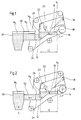
- Figures 1 and 2 show two purely exemplary embodiments of a device 10 for removing the inside the loop of a circulating drainage sieve 12 of a former, in particular a twin wire former, a paper machine of white water.
- a collecting basin 14 is arranged within the wire loop, in the white water 16 is collected, in particular with drainage elements 18 provided areas.
- the collection basin 14 has an at least substantially airtight hood 20 provided.
- This hood 20 can be evacuated by a suction system 22 in order to Separate collected white water from the air within the sieve loop.
- the collecting basin 14 is followed by a channel 24 lying overall below the water level N 1 of this collecting basin 14, via which the white water can be discharged generally transversely to the machine or wire running direction I.
- the collecting basin 14 has a large surface area and can extend up to the two sides of the chair on the driver and drive side of the paper machine or can be limited laterally by these sides of the chair.
- the collecting basin 14 can thus be formed in particular by these sides of the chair and corresponding cross members. As can be seen from FIGS. 1 and 2, the bottom of the collecting container 14 drops towards the channel 24.
- the white water is accumulated in the collecting basin 14 in order to maintain the water level N 1 in the collecting basin 14 above the channel 24.
- the storage wall 26 in question ultimately also delimits the collecting container 14 from the channel 24, which is connected to the collecting container 14 via the free area below the storage wall 26.
- the channel 24 can be open or closed at the top. It is essential that the water level N 2 in this channel 24 is lower than the water level or the water level N 1 in the collecting container 14.
- the sides of the hood 20 which extend transversely to the machine direction I are preferably free of openings.
- the only openings to the atmosphere are therefore the openings on the drainage elements required Front of the machine.
- the flow velocity v s of the white water in the suction area or in the area of the collecting basin 14 is preferably less than about 1 m / s, as a result of which a better degree of ventilation is achieved. In particular, it can be less than about 0.5 m / s and preferably less than about 0.2 m / s.
- the length LE of the suction area considered in machine direction I is expediently larger than about 0.5 m. In particular, it can be larger than about 1 m and preferably greater than about 2 m. As with the two figures 1 and 2 can be seen, this can be viewed in the machine running direction I. Length LE of the suction area is at least substantially the same as that in the machine direction I considered extension of the collection basin 14.
- the channel 24 extends laterally out of the sieve area out.
- a channel 28 which is open at the top, for example, is connected to the channel 14 connected to the collecting basin 14 laterally outside the screening area.
- the white water is fed via this channel 28 to a white water container 30 arranged outside the sieve area and the former area.
- the water level N 4 in the channel 28 is equal to the water level N 3 in the white water tank 30.
- the white water is the White water tank 30 supplied via this pipe 32.
- the pipeline 32 of the embodiment according to FIG. 2 is completely filled with white water.
- the clear height or the inner diameter of this pipeline 32 is at least substantially equal to the clear height of the channel 24 adjoining the collecting basin 14.
- the water level N 3 in the white water tank 30 is higher than the water level in the pipeline 32 and the water level N 2 in the channel 24 adjoining the collecting basin 14.
- the water level N 2 in the channel 24 adjoining the collecting basin 14 is therefore lower than the water levels N 1 , N 3 in the collecting basin 14 and the white water tank 30. Furthermore, the water level N 1 in the collecting basin 14 is higher than that Water level N 3 in the white water tank 30.
- N 2 can, for example, also be higher than N 3 , or, for example when the channel 24 is closed, also higher than N 1 .
Abstract
Bei einem Verfahren und einer entsprechenden Vorrichtung zum Abführen des
innerhalb der Schlaufe eines umlaufenden Entwässerungssiebes (12) eines Formers,
insbesondere eines Doppelsiebformers, einer Papiermaschine anfallenden
Siebwassers (16) wird das Siebwasser durch ein innerhalb der Schlaufe angeordnetes
Sammelbecken (14) aufgefangen, das aufgefangene Siebwasser durch Absaugen des
Bereichs oberhalb des Sammelbeckens noch innerhalb der Siebschlaufe von der
Luft getrennt und das Siebwasser über wenigstens einen sich an das
Sammelbecken anschließenden, unterhalb dessen Wasserspiegels (N1) liegenden
Kanal (24) aus dem Sammelbecken entfernt.

Description
Die Erfindung betrifft ein Verfahren sowie eine Vorrichtung zum Abführen des innerhalb der Schlaufe eines umlaufenden Entwässerungssiebes eines Formers einer Papiermaschine anfallenden Siebwassers. Verfahren und Vorrichtungen dieser Art sind beispielsweise aus der EP 0 258 918 B1, US 4 895 623, AT-PS 293 855 und US 2 893 486 bekannt.The invention relates to a method and a device for removing the within the loop of a circulating dewatering screen of a former a paper machine of white water. Methods and devices of this type are, for example, from EP 0 258 918 B1, US 4,895,623, AT-PS 293,855 and US 2,893,486.
Bisher war es allgemein üblich, das in einer Siebschlaufe entwässerte Siebwasservolumen zusammen mit der mitgeförderten Luft durch eine offene Rinne aus dem Siebbereich zu fördern und die Luft durch Absaugstutzen aus dem Siebinnenraum und dem Rinnenbereich abzusaugen. Dies bringt u.a. den Nachteil mit sich, daß außerhalb des Maschinengestells relativ viel Platz für die Rinnenverlegung und die Installation von Abscheidern erforderlich ist.So far, it has been common practice to have the volume of white water drained in a sieve loop together with the conveyed air through an open channel to promote from the sieve area and the air through suction nozzle from the Vacuum the interior of the sieve and the gutter area. Among other things, this brings the disadvantage with the fact that outside the machine frame there is a relatively large amount of space for the gutter laying and the installation of separators is required.
Ziel der Erfindung ist es, ein verbessertes Verfahren sowie eine verbesserte Vorrichtung der eingangs genannten Art zu schaffen, bei denen die zuvor genannten Nachteile beseitigt sind.The aim of the invention is to provide an improved method and an improved device to create the type mentioned, in which the aforementioned Disadvantages are eliminated.
Erfindungsgemäß wird diese Aufgabe gelöst durch ein Verfahren zum Abführen des innerhalb der Schlaufe eines umlaufenden Entwässerungssiebes eines Formers, insbesondere eines Doppelsiebformers, einer Papiermaschine anfallenden Siebwassers, bei dem das Siebwasser durch ein innerhalb der Schlaufe angeordnetes Sammelbecken aufgefangen, das aufgefangene Siebwasser durch Absaugen des Bereichs oberhalb des Sammelbeckens noch innerhalb der Siebschlaufe von der Luft getrennt und das Siebwasser über wenigstens einen sich an das Sammelbecken anschließenden, unterhalb dessen Wasserspiegels liegenden Kanal aus dem Sammelbecken entfernt wird.According to the invention, this object is achieved by a method for removal inside the loop of a circulating dewatering screen of a former, in particular a twin wire former, a paper machine White water, in which the white water is arranged by a within the loop Collection basin collected, the collected white water by suction the area above the collecting basin still within the sieve loop separated from the air and the white water over at least one itself adjoining the reservoir, below the water level Canal is removed from the collection basin.
Demnach wird die anfallende Siebwassermenge bereits innerhalb der Siebschlaufe bzw. im Siebschiff so weit von der Luft getrennt, daß sie über eine vollständig mit Siebwasser gefüllte Rohrleitung aus dem Maschinenbereich abgeführt werden kann. Der bisher erforderliche Platzaufwand außerhalb des Maschinengestells für die Rinnenverlegung und die Installation von Abscheidern wird daher deutlich verringert. Es ergibt sich eine Einsparung an Kanälen und an erforderlichem Gebäudevolumen. Entsprechend werden Möglichkeiten für Standardanordnungen geschaffen, da die Gefahr einer möglichen Kollision mit dem Gebäude auf ein Minimum reduziert ist. Die bisher erforderlichen Abscheider neben der Papiermaschine können entfallen. Überdies ergibt sich eine einfachere Stuhlung, nachdem für die Siebwasserabfuhr auch keine Stuhlungsdurchbrüche mehr erforderlich sind. Diese genannten Vorteile wirken sich insbesondere bei Doppelsiebformern positiv aus.Accordingly, the amount of white water generated is already within the wire loop or in the sieve ship so far from the air that they are completely Pipeline filled with white water discharged from the machine area can be. The space previously required outside the machine frame for gutter laying and the installation of separators significantly reduced. There is a saving in channels and in the necessary Building volume. The possibilities for standard arrangements are correspondingly created because of the risk of a possible collision with the building is reduced to a minimum. The previously required separators next to the paper machine can be omitted. In addition, there is a simpler stool, since no breakthroughs in the stool are required for white water drainage are. These advantages are particularly effective in twin wire formers positive.
Vorzugsweise wird ein möglichst großflächiges Sammelbecken verwendet.Preferably, the largest possible collection basin is used.
Das Sammelbecken erstreckt sich zweckmäßigerweise bis zu den beiden Stuhlungsseiten auf der Führer- und Triebseite und ist vorzugsweise durch diese beiden Stuhlungsseiten und entsprechende Quertraversen gebildet.The collecting basin expediently extends to the two sides of the chair on the leader and drive side and is preferably through these two Chair sides and corresponding cross members formed.
Gemäß einer bevorzugten praktischen Ausgestaltung des erfindungsgemäßen Verfahrens wird das Sammelbecken mit einer zumindest im wesentlichen luftdichten Haube versehen und diese Haube durch ein Absaugsystem evakuiert, um die Luft von dem im Sammelbecken aufgefangenen Siebwasser zu trennen. Dabei wird zweckmäßigerweise eine Haube verwendet, deren sich quer zur Maschinenlaufrichtung erstreckende Seiten frei von Öffnungen sind. Die einzigen Öffnungen zur Atmosphäre sind demzufolge die an den betreffenden Entwässerungselementen erforderlichen Öffnungen an den Stirnseiten der Papiermaschine.According to a preferred practical embodiment of the invention The method of collecting basins is at least essentially airtight Provide hood and this hood evacuated by a suction system separate the air from the white water collected in the collection basin. there a hood is expediently used, whose cross-machine direction extending sides are free of openings. The only openings to the atmosphere are therefore those on the drainage elements in question required openings on the end faces of the paper machine.
In dem Sammelbecken kann das Siebwasser gestaut werden, so daß der oberhalb des Kanals liegende Wasserspiegel im Sammelbecken aufrechterhalten wird und das Siebwasser unterhalb dieses Wasserspiegels aus dem Siebbereich herausfließen kann.The white water can be stowed in the collecting basin, so that the above the water level in the collecting basin is maintained and the white water flows out of the screen area below this water level can.
Die Strömungsgeschwindigkeit des Siebwassers im Absaugbereich bzw. im Bereich des Sammelbeckens ist vorteilhafterweise kleiner als etwa 1 m/s. Sie kann insbesondere kleiner als etwa 0,5 m/s und vorzugsweise kleiner als etwa 0,2 m/s sein. Mit einer solchen relativ geringen Geschwindigkeit ergibt sich ein besserer Entlüftungsgrad.The flow speed of the white water in the suction area or in the area the collecting basin is advantageously less than about 1 m / s. she can in particular less than about 0.5 m / s and preferably less than about 0.2 m / s his. With such a relatively low speed, the result is better Venting degrees.
Die in Maschinenlaufrichtung betrachtete Länge des Absaugbereichs ist zweckmäßigerweise größer als etwa 0,5 m. Sie kann insbesondere größer als etwa 1 m und vorzugsweise größer als etwa 2 m sein.The length of the suction area viewed in the machine direction is expedient greater than about 0.5 m. In particular, it can be larger than approximately 1 m and preferably be greater than about 2 m.
Die in Maschinenlaufrichtung betrachtete Länge des Absaugbereichs kann insbesondere zumindest im wesentlichen gleich der in Maschinenlaufrichtung betrachteten Ausdehnung des Sammelbeckens sein.The length of the suction area viewed in the machine running direction can in particular be at least substantially the same as that viewed in the machine direction Extension of the collection basin.
Gemäß einer bevorzugten praktischen Ausgestaltung des erfindungsgemäßen Verfahrens ist der sich an das Sammelbecken anschließende Kanal nach oben offen oder geschlossen, wobei das Wasserniveau in diesem vorzugsweise zumindest im wesentlichen vollständig mit Siebwasser gefüllten Kanal tiefer liegt als das Wasserniveau in dem Sammelbecken. According to a preferred practical embodiment of the invention The process is the upward canal adjoining the collecting basin open or closed, the water level in this preferably at least channel completely filled with white water is lower than that Water level in the pool.
Über den sich an das Sammelbecken anschließenden Kanal kann das Siebwasser seitlich aus dem Siebbereich herausgeführt werden. Dabei kann seitlich außerhalb des Siebbereichs an diesen Kanal z.B. wenigstens eine Rohrleitung angeschlossen sein, über die das Siebwasser insbesondere einem außerhalb des Siebbereichs und des Formerbereichs angeordneten Siebwasserbehälter zugeführt wird. Über diesen Siebwasserbehälter kann das Siebwasser dann wieder dem Prozeß zugeführt werden.The white water can be discharged through the canal adjoining the collecting basin are led out of the side of the screen area. This can be done laterally outside the sieve area on this channel e.g. at least one pipe be connected via which the white water, in particular one outside the Screen area and the former area arranged screen water tank supplied becomes. The white water can then again via this white water tank be fed into the process.
Dabei ist es von Vorteil, wenn die lichte Höhe bzw. der Innendurchmesser der zumindest im wesentlichen vollständig mit Siebwasser gefüllten Rohrleitung zumindest im wesentlichen gleich der lichten Höhe des sich an das Sammelbecken anschließenden Kanals ist.It is advantageous if the clear height or the inner diameter of the at least essentially completely pipeline filled with white water at least essentially equal to the inside height of the pool subsequent channel.
Gemäß einer zweckmäßigen Ausgestaltung des erfindungsgemäßen Verfahrens liegt das Wasserniveau in dem Siebwasserbehälter höher als das Wasserniveau in der Rohrleitung und in dem sich an das Sammelbecken anschließenden Kanal.According to an expedient embodiment of the method according to the invention the water level in the white water tank is higher than the water level in the pipeline and in the channel adjoining the collecting basin.
Gemäß einer weiteren vorteilhaften Ausgestaltung des erfindungsgemäßen Verfahrens ist seitlich außerhalb des Siebbereichs an den mit dem Sammelbecken verbundenen Kanal wenigstens ein oben vorzugsweise offener Kanal angeschlossen, über den das Siebwasser einem außerhalb des Siebbereichs und des Formerbereichs angeordneten Siebwasserbehälter zugeführt wird. Über diesen Siebwasserbehälter kann das Siebwasser wieder dem Prozeß zugeführt werden.According to a further advantageous embodiment of the method according to the invention is on the side outside of the sieve area at the one with the collecting basin connected channel connected at least one preferably open channel at the top, through which the white water is outside the sieve area and Forming area arranged white water tank is supplied. About this White water tank, the white water can be returned to the process.
Gemäß einer zweckmäßigen praktischen Ausgestaltung liegt das Wasserniveau in dem sich an das Sammelbecken anschließenden Kanal tiefer als die Wasserniveaus in dem Sammelbecken und dem Siebwasserbehälter. According to an expedient practical embodiment, the water level is in the channel adjoining the collection basin is lower than the water levels in the collecting basin and the white water tank.
In bestimmten Fällen ist es auch von Vorteil, wenn das Wasserniveau in dem Sammelbehälter höher liegt als das Wasserniveau in dem Siebwasserbehälter und das Wasserniveau in diesem Siebwasserbehälter höher liegt als das Wasserniveau in dem sich an das Sammelbecken anschließenden Kanal.In certain cases it is also advantageous if the water level in the Collection tank is higher than the water level in the white water tank and the water level in this white water tank is higher than the water level in the canal adjoining the collecting basin.
Grundsätzlich besteht auch die Möglichkeit, daß das Wasserniveau in dem Siebwasserbehälter kleiner als das Wasserniveau in dem Sammelbecken ist, wobei die Höhendifferenz insbesondere größer als 100 mm und vorzugsweise größer als 300 mm ist.Basically, there is also the possibility that the water level in the white water tank is less than the water level in the reservoir, where the height difference in particular greater than 100 mm and preferably greater than Is 300 mm.
Weiterhin besteht die Möglichkeit, daß seitlich außerhalb des Siebbereichs an den mit dem Sammelbecken verbundenen Kanal wenigstens eine Rohrleitung angeschlossen ist, über die das Siebwasser ohne Passierung eines Siebwasserbehälters in die Siebwasserzufuhr zurückgeführt wird. Hierdurch entsteht sowohl ein raum- als auch kostenmäßiger Vorteil gegenüber dem Vorhandensein eines Siebwasserbehälters und der Durchführung des Siebwassers durch denselben.There is also the possibility that the outside of the screen area to the connected to the collecting basin channel at least one pipeline over which the white water is passed without passing through a white water tank is returned to the white water supply. This creates both a space and cost advantage over the presence of a White water tank and the implementation of the white water through the same.
Von Vorteil ist auch, wenn die Strömungsgeschwindigkeit in dem Kanal größer als 1,2 m/s und vorzugsweise größer als 2,4 m/s ist, wobei dessen Querschnittsfläche insbesondere kleiner als 2 m2 und vorzugsweise kleiner als 1 m2 ist.It is also advantageous if the flow velocity in the channel is greater than 1.2 m / s and preferably greater than 2.4 m / s, the cross-sectional area thereof being in particular less than 2 m 2 and preferably less than 1 m 2 .
Die Strömungsgeschwindigkeit in dem sich an das Sammelbecken anschließenden Kanal, über den das Siebwasser zunächst in Querrichtung seitlich aus dem Siebbereich herausgeführt werden kann, kann insbesondere durch die Wahl der Differenz zwischen dem Wasserniveau in dem Sammelbecken und dem Wasserniveau in dem Siebwasserbehälter eingestellt werden. Demnach können beliebige Siebwassermengen abgeführt werden, was bei den bisher üblichen Vorrichtungen mit freiem Gefälle nicht möglich war. Da die Strömungsgeschwindigkeit im sich an das Sammelbecken anschließenden Kanal relativ groß ist, ergeben sich für die seitlichen Durchbrüche relativ kleine Querschnittsflächen.The flow velocity in the adjoining the collecting basin Canal, through which the white water is first moved laterally out of the Screen area can be brought out, in particular by the choice of Difference between the water level in the reservoir and the water level be set in the white water tank. Accordingly, any White water quantities are discharged, which is the case with the devices customary to date was not possible with a free slope. Because the flow rate in itself the collecting basin connecting channel is relatively large, arise for the side openings relatively small cross-sectional areas.
Die erfindungsgemäße Vorrichtung umfaßt entsprechend ein innerhalb der Siebschlaufe angeordnetes Sammelbecken, das mit wenigstens einer zumindest im wesentlichen luftdichten, durch ein Absaugsystem evakuierbaren Haube versehen ist, um das aufgefangene Siebwasser noch innerhalb der Siebschlaufe von der Luft zu trennen, und wenigstens einen sich an das Sammelbecken anschließenden, unterhalb dessen Wasserspiegels liegenden Kanal zum Abführen des Siebwassers aus dem Sammelbecken.The device according to the invention accordingly comprises a within the sieve loop arranged collection basin, which with at least one at least in essential airtight hood, evacuable by a suction system is to get the collected white water still within the wire loop of the Separating air, and at least one adjoining the collecting basin, channel below the water level to drain the white water from the pool.
Bevorzugte Ausführungsformen der erfindungsgemäßen Vorrichtung sind in den Unteransprüchen angegeben.Preferred embodiments of the device according to the invention are in the Subclaims specified.
Die Erfindung wird im folgenden anhand von Ausführungsbeispielen unter Bezugnahme auf die Zeichnung näher erläutert; in dieser zeigen:
- Figur 1
- eine schematische Darstellung einer ersten Ausführungsform einer Vorrichtung zum Abführen des innerhalb der Schlaufe eines umlaufenden Entwässerungssiebes eines Doppelsiebformers einer Papiermaschine anfallenden Siebwassers und
- Figur 2
- eine schematische Darstellung einer weiteren Ausführungsform der Vorrichtung.
- Figure 1
- a schematic representation of a first embodiment of a device for removing the white water accumulating within the loop of a circulating drainage screen of a twin wire former of a paper machine and
- Figure 2
- a schematic representation of a further embodiment of the device.
Die Figuren 1 und 2 zeigen zwei rein beispielhafte Ausführungsformen einer Vorrichtung
10 zum Abführen des innerhalb der Schlaufe eines umlaufenden Entwässerungssiebes
12 eines Formers, insbesondere eines Doppelsiebformers,
einer Papiermaschine anfallenden Siebwassers. Figures 1 and 2 show two purely exemplary embodiments of a device
10 for removing the inside the loop of a circulating
Innerhalb der Siebschlaufe ist ein Sammelbecken 14 angeordnet, in dem Siebwasser
16 aufgefangen wird, das insbesondere aus mit Entwässerungselementen
18 versehenen Bereichen stammt.A
Das Sammelbecken 14 ist mit einer zumindest im wesentlichen luftdichten Haube
20 versehen. Diese Haube 20 ist durch ein Absaugsystem 22 evakuierbar, um das
aufgefangene Siebwasser noch innerhalb der Siebschlaufe von der Luft zu trennen.The
Wie anhand der beiden Figuren 1 und 2 zu erkennen ist, schließt sich an das
Sammelbecken 14 ein insgesamt unterhalb des Wasserspiegels N1 dieses Sammelbeckens
14 liegender Kanal 24 an, über den das Siebwasser allgemein quer
zur Maschinen- oder Sieblaufrichtung I abgeführt werden kann.As can be seen on the basis of the two FIGS. 1 and 2, the
Das Sammelbecken 14 ist großflächig ausgestaltet und kann bis zu den beiden
Stuhlungsseiten auf der Führer- und Triebseite der Papiermaschine reichen bzw.
seitlich durch diese Stuhlungsseiten begrenzt sein. Das Sammelbecken 14 kann
somit insbesondere durch diese Stuhlungsseiten und entsprechende Quertraversen
gebildet sein.
Wie anhand der Figuren 1 und 2 zu erkennen ist, fällt der Boden des Sammelbehälters
14 zum Kanal 24 hin ab.The
As can be seen from FIGS. 1 and 2, the bottom of the collecting
Im Sammelbecken 14 wird das Siebwasser gestaut, um den oberhalb des Kanals
24 liegenden Wasserspiegel N1 im Sammelbecken 14 aufrechtzuerhalten. Durch
die betreffende Stauwand 26 erfolgt letztlich auch die Abgrenzung des Sammelbehälters
14 von dem Kanal 24, der über den freien Bereich unterhalb der Stauwand
26 mit dem Sammelbehälter 14 verbunden ist. The white water is accumulated in the
Der Kanal 24 kann nach oben offen oder geschlossen sein. Wesentlich ist, daß
das Wasserniveau N2 in diesem Kanal 24 tiefer liegt als das Wasserniveau bzw.
der Wasserspiegel N1 im Sammelbehälter 14.The
Die sich quer zur Maschinenlaufrichtung I erstreckenden Seiten der Haube 20 sind
vorzugsweise frei von Öffnungen. Die einzigen Öffnungen zur Atmosphäre sind
daher die an den Entwässerungselementen erforderlichen Öffnungen an den
Stirnseiten der Maschine.The sides of the
Die Strömungsgeschwindigkeit vs des Siebwassers im Absaugbereich bzw. im
Bereich des Sammelbeckens 14 ist vorzugsweise kleiner als etwa 1 m/s, wodurch
ein besserer Entlüftungsgrad erreicht wird. Sie kann insbesondere kleiner als etwa
0,5 m/s und vorzugsweise kleiner als etwa 0,2 m/s sein.The flow velocity v s of the white water in the suction area or in the area of the collecting
Die in Maschinenlaufrichtung I betrachtete Länge LE des Absaugbereichs ist
zweckmäßigerweise größer als etwa 0,5 m. Sie kann insbesondere größer als
etwa 1 m und vorzugsweise größer als etwa 2 m sein. Wie anhand der beiden Figuren
1 und 2 zu erkennen ist, kann diese in Maschinenlaufrichtung I betrachtete
Länge LE des Absaugbereichs zumindest im wesentlichen gleich der in Maschinenlaufrichtung
I betrachteten Ausdehnung des Sammelbeckens 14 sein.The length LE of the suction area considered in machine direction I is
expediently larger than about 0.5 m. In particular, it can be larger than
about 1 m and preferably greater than about 2 m. As with the two figures
1 and 2 can be seen, this can be viewed in the machine running direction I.
Length LE of the suction area is at least substantially the same as that in the machine direction
I considered extension of the
Bei beiden Ausführungsformen erstreckt sich der Kanal 24 seitlich aus dem Siebbereich
heraus.In both embodiments, the
Bei der in der Figur 1 dargestellten Ausführungsform ist seitlich außerhalb des
Siebbereichs an den mit dem Sammelbecken 14 verbundenen Kanal 14 ein oben
beispielsweise offener Kanal 28 angeschlossen. Über diesen Kanal 28 wird das
Siebwasser einem außerhalb des Siebbereichs und des Formerbereichs angeordneten
Siebwasserbehälter 30 zugeführt. Im vorliegenden Fall ist das Wasserniveau
N4 in dem Kanal 28 gleich dem Wasserniveau N3 in dem Siebwasserbehälter
30.In the embodiment shown in FIG. 1, a
Dagegen ist bei der in der Figur 2 dargestellten Ausführungsform seitlich außerhalb
des Siebbereichs an den mit dem Sammelbecken 14 verbundenen Kanal 24
eine Rohrleitung 32 angeschlossen. In diesem Fall wird das Siebwasser dem
Siebwasserbehälter 30 über diese Rohrleitung 32 zugeführt.In contrast, is in the embodiment shown in Figure 2 laterally outside
of the screening area to the
Während der bei der Ausführungsform gemäß Figur 1 vorgesehene Kanal 28
ganz oder auch nur teilweise gefüllt sein kann, ist die Rohrleitung 32 der Ausführungsform
gemäß Figur 2 vollständig mit Siebwasser gefüllt. Die lichte Höhe
bzw. der Innendurchmesser dieser Rohrleitung 32 ist im vorliegenden Fall zumindest
im wesentlichen gleich der lichten Höhe des sich an das Sammelbecken 14
anschließenden Kanals 24.
Wie anhand der Figur 2 zu erkennen ist, liegt das Wasserniveau N3 in dem Siebwasserbehälter
30 höher als das Wasserniveau in der Rohrleitung 32 und das
Wasserniveau N2 in dem sich an das Sammelbecken 14 anschließenden Kanal
24.While the
As can be seen from FIG. 2, the water level N 3 in the
Bei beiden Ausführungsformen liegt somit das Wasserniveau N2 in dem sich an
das Sammelbecken 14 anschließenden Kanal 24 tiefer als die Wasserniveaus N1,
N3 in dem Sammelbecken 14 und dem Siebwasserbehälter 30. Überdies liegt das
Wasserniveau N1 in dem Sammelbecken 14 höher als das Wasserniveau N3 in
dem Siebwasserbehälter 30.In both embodiments, the water level N 2 in the
Die obigen Niveauverhältnisse sind rein beispielhaft zu sehen. N2 kann z.B. auch
höher als N3, oder, bei geschlossenem Kanal 24, z.B. auch höher sein als N1. The above level relationships are to be seen purely as examples. N 2 can, for example, also be higher than N 3 , or, for example when the
- 1010
- Vorrichtung zum Abführen von SiebwasserDevice for removing white water
- 1212
- Entwässerungssiebdewatering
- 1414
- Sammelbeckenmelting pot
- 1616
- Siebwasserwhite water
- 1818
- Entwässerungselementdewatering element
- 2020
- HaubeHood
- 2222
- Absaugsystemsuction
- 2424
- Kanalchannel
- 2626
- Stauwandretaining wall
- 2828
- Kanalchannel
- 3030
- Siebwasserbehälterwhite water tank
- 3232
- Rohrleitungpipeline
- LELE
- Länge des AbsaugbereichsLength of the suction area
- N1 N 1
- Wasserniveauwater level
- N2 N 2
- Wasserniveauwater level
- N3 N 3
- Wasserniveauwater level
- II
- Maschinen- oder SieblaufrichtungMachine or wire direction
Claims (42)
dadurch gekennzeichnet, daß ein großflächiges Sammelbecken (14) verwendet wird.Method according to claim 1,
characterized in that a large collecting basin (14) is used.
dadurch gekennzeichnet, daß ein Sammelbecken (14) verwendet wird , das bis zu den beiden Stuhlungsseiten auf der Führer- und Triebseite der Papiermaschine reicht oder durch diese Stuhlungsseiten begrenzt ist. The method of claim 1 or 2,
characterized in that a collecting basin (14) is used which extends to the two sides of the chair on the driver and drive side of the paper machine or is limited by these sides of the chair.
dadurch gekennzeichnet, daß das Sammelbecken (14) mit einer zumindest im wesentlichen luftdichten Haube (20) versehen und diese Haube (20) durch ein Absaugsystem (12) evakuiert wird, um die Luft von dem im Sammelbecken (14) aufgefangenen Siebwasser (16) zu trennen.Method according to one of the preceding claims,
characterized in that the collecting basin (14) is provided with an at least substantially air-tight hood (20) and this hood (20) is evacuated by a suction system (12) in order to extract the air from the white water (16) collected in the collecting basin (14) to separate.
dadurch gekennzeichnet, daß eine Haube (20) verwendet wird, deren sich quer zur Maschinenlaufrichtung (I) erstreckende Seiten frei von Öffnungen sind.Method according to claim 4,
characterized in that a hood (20) is used, the sides of which extend transversely to the machine direction (I) and are free of openings.
dadurch gekennzeichnet, daß das Siebwasser (16) in dem Sammelbecken (14) gestaut wird, um den oberhalb des Kanals (24) liegenden Wasserspiegel (N1) aufrechtzuerhalten.Method according to one of the preceding claims,
characterized in that the white water (16) is accumulated in the collecting basin (14) in order to maintain the water level (N 1 ) above the channel (24).
dadurch gekennzeichnet, daß die Strömungsgeschwindigkeit (vs) des Siebwassers (16) im Absaugbereich bzw. im Bereich des Sammelbeckens (14) kleiner als etwa 1 m/s gewählt wird.Method according to one of the preceding claims,
characterized in that the flow velocity (v s ) of the white water (16) in the suction area or in the area of the collecting basin (14) is selected to be less than approximately 1 m / s.
dadurch gekennzeichnet, daß die Strömungsgeschwindigkeit (vs) des Siebwassers (16) im Absaugbereich bzw. im Bereich des Sammelbeckens (14) kleiner als etwa 0,5 m/s und vorzugsweise kleiner als etwa 0,2 m/s gewählt wird.Method according to one of the preceding claims,
characterized in that the flow velocity (v s ) of the white water (16) in the suction area or in the area of the collecting basin (14) is chosen to be less than about 0.5 m / s and preferably less than about 0.2 m / s.
dadurch gekennzeichnet, daß die in Maschinenlaufrichtung (I) betrachtete Länge (LE) des Absaugbereichs größer als etwa 0,5 m gewählt wird.Method according to one of the preceding claims,
characterized in that the length (LE) of the suction area considered in the machine direction (I) is selected to be greater than approximately 0.5 m.
dadurch gekennzeichnet, daß die in Maschinenlaufrichtung (I) betrachtete Länge (LE) des Absaugbereichs größer als etwa 1 m und vorzugsweise größer als etwa 2 m gewählt wird.Method according to claim 9,
characterized in that the length (LE) of the suction area considered in the machine direction (I) is selected to be greater than approximately 1 m and preferably greater than approximately 2 m.
dadurch gekennzeichnet, daß die in Maschinenlaufrichrung (I) betrachtete Länge (LE) des Absaugbereichs zumindest im wesentlichen gleich der in Maschinenlaufrichtung betrachteten Ausdehnung des Sammelbeckens (14) gewählt wird.Method according to one of the preceding claims,
characterized in that the length (LE) of the suction area viewed in the machine running direction (I) is selected at least substantially equal to the extension of the collecting basin (14) viewed in the machine running direction.
dadurch gekennzeichnet, daß der sich an das Sammelbecken (14) anschließende Kanal (24) nach oben offen oder geschlossen ist und das Wasserniveau (N2) in diesem vorzugsweise zumindest im wesentlichen vollständig mit Siebwasser (16) gefüllten Kanal (24) tiefer liegt als das Wasserniveau (N1) in dem Sammelbecken (24).Method according to one of the preceding claims,
characterized in that the channel (24) adjoining the collecting basin (14) is open or closed at the top and the water level (N 2 ) in this channel (24) is preferably at least substantially completely filled with white water (16) than the water level (N 1 ) in the reservoir (24).
dadurch gekennzeichnet, daß das Siebwasser (16) über den sich an das Sammelbecken (14) anschließenden Kanal (24) seitlich aus dem Siebbereich herausgeführt wird.Method according to claim 12,
characterized in that the white water (16) is led laterally out of the screen area via the channel (24) adjoining the collecting basin (14).
dadurch gekennzeichnet, daß seitlich außerhalb des Siebbereichs an den mit dem Sammelbecken (14) verbundenen Kanal (24) wenigstens eine Rohrleitung (32) angeschlossen ist, über die das Siebwasser (16) einem außerhalb des Siebbereichs und des Formerbereichs angeordneten Siebwasserbehälter (30) zugeführt wird.A method according to claim 13,
characterized in that at least one pipe (32) is connected to the side of the sieve area to the channel (24) connected to the collecting basin (14), via which the white water (16) is fed to a white water container (30) arranged outside the sieve area and the former area becomes.
dadurch gekennzeichnet, daß die lichte Höhe bzw. der Innendurchmesser der zumindest im wesentlichen vollständig mit Siebwasser (16) gefüllten Rohrleitung (32) zumindest im wesentlichen gleich der lichten Höhe des sich an das Sammelbecken (14) anschließenden Kanals (24) gewählt wird.The method of claim 14
characterized in that the clear height or the inside diameter of the pipeline (32), which is at least substantially completely filled with white water (16), is selected at least substantially equal to the clear height of the channel (24) adjoining the collecting basin (14).
dadurch gekennzeichnet, daß das Wasserniveau (N3) in dem Siebwasserbehälter (30) höher liegt als das Wasserniveau in der Rohrleitung (32) und das Wasserniveau (N2) in dem sich an das Sammelbecken (14) anschließenden Kanal (24).A method according to claim 14 or 15,
characterized in that the water level (N 3 ) in the white water tank (30) is higher than the water level in the pipeline (32) and the water level (N 2 ) in the channel (24) adjoining the collecting basin (14).
dadurch gekennzeichnet, daß seitlich außerhalb des Siebbereichs an den mit dem Sammelbecken verbundenen Kanal wenigstens ein oben vorzugsweise offener Kanal angeschlossen ist, über den das Siebwasser einem außerhalb des Siebbereichs und des Formerbereichs angeordneten Siebwasserbehälter zugeführt wird.A method according to claim 13,
characterized in that at least one channel, preferably open at the top, is connected laterally outside the screen area to the channel connected to the collecting basin, via which the white water is fed to a screen water container arranged outside the screen area and the former area.
dadurch gekennzeichnet, daß das Wasserniveau in dem sich an das Sammelbecken anschließenden Kanal tiefer liegt als die Wasserniveaus in dem Sammelbecken und dem Siebwasserbehälter.Method according to one of the preceding claims,
characterized in that the water level in the channel adjoining the collecting basin is lower than the water levels in the collecting basin and the white water tank.
dadurch gekennzeichnet, daß das Wasserniveau in dem Sammelbecken höher liegt als das Wasserniveau in dem Siebwasserbehälter und das Wasserniveau in diesem Siebwasserbehälter höher liegt als das Wasserniveau in dem sich an das Sammelbecken anschließenden Kanal.Method according to one of the preceding claims,
characterized in that the water level in the collecting basin is higher than the water level in the white water tank and the water level in this white water tank is higher than the water level in the channel adjoining the collecting basin.
dadurch gekennzeichnet, daß das Wasserniveau (N3) in dem Siebwasserbehälter (30) kleiner als das Wasserniveau (N1) in dem Sammelbecken (14) ist, wobei die Höhendifferenz insbesondere größer als 100 mm und vorzugsweise größer als 300 mm ist.Method according to one of the preceding claims,
characterized in that the water level (N 3 ) in the white water tank (30) is smaller than the water level (N 1 ) in the collecting basin (14), the height difference being in particular greater than 100 mm and preferably greater than 300 mm.
dadurch gekennzeichnet, daß seitlich außerhalb des Siebbereichs an den mit dem Sammelbecken (14) verbundenen Kanal (24) wenigstens eine Rohrleitung (32) angeschlossen ist, über die das Siebwasser (16) ohne Passierung eines Siebwasserbehälters in die Siebwasserzufuhr zurückgeführt wird. A method according to claim 13,
characterized in that at least one pipeline (32) is connected laterally outside the sieve area to the channel (24) connected to the collecting basin (14), via which the white water (16) is returned to the white water supply without passing through a white water container.
dadurch gekennzeichnet, daß die Strömungsgeschwindigkeit in dem Kanal (24) größer als 1,2 m/s und vorzugsweise größer als 2,4 m/s ist, wobei dessen Querschnittsfläche insbesondere kleiner als 2 m2 und vorzugsweise kleiner als 1 m2 ist.Method according to one of the preceding claims,
characterized in that the flow velocity in the channel (24) is greater than 1.2 m / s and preferably greater than 2.4 m / s, the cross-sectional area thereof being in particular less than 2 m 2 and preferably less than 1 m 2 .
dadurch gekennzeichnet, daß das Sammelbecken (14) großflächig ausgestaltet ist.Device according to claim 23,
characterized in that the collecting basin (14) has a large area.
dadurch gekennzeichnet, daß das Sammelbecken (14) bis zu den beiden Stuhlungsseiten auf der Führer- und Triebseite der Papiermaschine reicht oder durch diese Stuhlungsseiten begrenzt ist. Device according to claim 23 or 24,
characterized in that the collecting basin (14) extends to the two sides of the chair on the driver and drive side of the paper machine or is limited by these sides of the chair.
dadurch gekennzeichnet, daß die sich quer zur Maschinenlaufrichtung (I) erstreckende Seiten der Haube (20) frei von Öffnungen sind.Device according to one of claims 23 to 25,
characterized in that the sides of the hood (20) extending transversely to the machine direction (I) are free of openings.
dadurch gekennzeichnet, daß das Siebwasser (16) in dem Sammelbecken (14) gestaut wird, um den oberhalb des Kanals (24) liegenden Wasserspiegel (N1) aufrechtzuerhalten.Device according to one of claims 23 to 26,
characterized in that the white water (16) is stowed in the collecting basin (14) in order to maintain the water level (N 1 ) lying above the channel (24).
dadurch gekennzeichnet, daß die Strömungsgeschwindigkeit (vs) des Siebwassers (16) im Absaugbereich bzw. im Bereich des Sammelbeckens (14) kleiner als etwa 1 m/s ist.Device according to one of claims 23 to 27,
characterized in that the flow velocity (v s ) of the white water (16) in the suction area or in the area of the collecting basin (14) is less than approximately 1 m / s.
dadurch gekennzeichnet, daß die Strömungsgeschwindigkeit (vs) des Siebwassers (16) im Absaugbereich bzw. im Bereich des Sammelbeckens (14) kleiner als etwa 0,5 m/s und vorzugsweise kleiner als etwa 0,2 m/s ist.Device according to one of claims 23 to 28,
characterized in that the flow velocity (v s ) of the white water (16) in the suction area or in the area of the collecting basin (14) is less than about 0.5 m / s and preferably less than about 0.2 m / s.
dadurch gekennzeichnet, daß die in Maschinenlaufrichtung (I) betrachtete Länge (LE) des Absaugbereichs größer als etwa 0,5 m ist.Device according to one of claims 23 to 29,
characterized in that the length (LE) of the suction area considered in the machine direction (I) is greater than approximately 0.5 m.
dadurch gekennzeichnet, daß die in Maschinenlaufrichtung (I) betrachtete Länge (LE) des Absaugbereichs größer als etwa 1 m und vorzugsweise größer als etwa 2 m ist.Apparatus according to claim 30,
characterized in that the length (LE) of the suction area considered in the machine direction (I) is greater than approximately 1 m and preferably greater than approximately 2 m.
dadurch gekennzeichnet, daß die in Maschinenlaufrichtung (I) betrachtete Länge (LE) des Absaugbereichs zumindest im wesentlichen gleich der in Maschinenlaufrichtung (I) betrachteten Ausdehnung des Sammelbeckens (14) ist.Device according to one of claims 23 to 31,
characterized in that the length (LE) of the suction area viewed in the machine direction (I) is at least substantially equal to the extension of the collecting basin (14) viewed in the machine direction (I).
dadurch gekennzeichnet, daß der sich an das Sammelbecken (14) anschließende Kanal (24) nach oben offen oder geschlossen ist und das Wasserniveau (N2) in diesem vorzugsweise zumindest im wesentlichen vollständig mit Siebwasser (16) gefüllten Kanal (24) tiefer liegt als das Wasserniveau (N1) in dem Sammelbecken (24).Device according to one of claims 23 to 32,
characterized in that the channel (24) adjoining the collecting basin (14) is open or closed at the top and the water level (N 2 ) in this channel (24), which is preferably at least substantially completely filled with white water (16), is lower than the water level (N 1 ) in the reservoir (24).
dadurch gekennzeichnet, daß sich der sich an das Sammelbecken (14) anschließende Kanal (24) seitlich aus dem Siebbereich herauserstreckt.Apparatus according to claim 33,
characterized in that the channel (24) adjoining the collecting basin (14) extends laterally out of the sieve area.
dadurch gekennzeichnet, daß seitlich außerhalb des Siebbereichs an den mit dem Sammelbecken (14) verbundenen Kanal (24) wenigstens eine Rohrleitung (32) angeschlossen ist, über die das Siebwasser (16) einem außerhalb des Siebbereichs und des Formerbereichs angeordneten Siebwasserbehälter (30) zuführbar ist.Apparatus according to claim 34,
characterized in that at least one pipeline (32) is connected laterally outside the sieve area to the channel (24) connected to the collecting basin (14), via which the white water (16) can be fed to a white water container (30) arranged outside the sieve area and the former area is.
dadurch gekennzeichnet, daß die lichte Höhe bzw. der Innendurchmesser der zumindest im wesentlichen vollständig mit Siebwasser (16) gefüllten Rohrleitung (32) zumindest im wesentlichen gleich der lichten Höhe des sich an das Sammelbecken (14) anschließenden Kanals (24) ist.Apparatus according to claim 35,
characterized in that the clear height or the inside diameter of the pipeline (32), which is at least substantially completely filled with white water (16), is at least substantially equal to the clear height of the channel (24) adjoining the collecting basin (14).
dadurch gekennzeichnet, daß das Wasserniveau (N3) in dem Siebwasserbehälter (30) höher liegt als das Wasserniveau in der Rohrleitung (32) und das Wasserniveau (N2) in dem sich an das Sammelbecken (14) anschließenden Kanal (24).Apparatus according to claim 35 or 36,
characterized in that the water level (N 3 ) in the white water tank (30) is higher than the water level in the pipeline (32) and the water level (N 2 ) in the channel (24) adjoining the collecting basin (14).
dadurch gekennzeichnet, daß seitlich außerhalb des Siebbereichs an den mit dem Sammelbecken (14) verbundenen Kanal (24) wenigstens ein oben vorzugsweise offener Kanal (28) angeschlossen ist, über den das Siebwasser (16) einem außerhalb des Siebbereichs und des Formerbereichs angeordneten Siebwasserbehälter (30) zuführbar ist.Apparatus according to claim 34,
characterized in that at least one channel (28), which is preferably open at the top, is connected to the channel (24) connected to the collecting basin (14) laterally outside the screen area, via which the white water (16) to a white water tank arranged outside the screen area and the former area ( 30) can be fed.
dadurch gekennzeichnet, daß das Wasserniveau (N2) in dem sich an das Sammelbecken (14) anschließenden Kanal (24) tiefer liegt als die Wasserniveaus in dem Sammelbecken (14) und dem Siebwasserbehälter (30).Device according to one of claims 23 to 38,
characterized in that the water level (N 2 ) in the channel (24) adjoining the collecting basin (14) is lower than the water levels in the collecting basin (14) and the white water tank (30).
dadurch gekennzeichnet, daß das Wasserniveau (N1) in dem Sammelbecken (14) höher liegt als das Wasserniveau (N3) in dem Siebwasserbehälter (30) und das Wasserniveau (N3) in diesem Siebwasserbehälter (30) höher liegt als das Wasserniveau (N2) in dem sich an das Sammelbecken (14) anschließenden Kanal (24).Device according to one of claims 23 to 39,
characterized in that the water level (N 1 ) in the collecting basin (14) is higher than the water level (N 3 ) in the white water tank (30) and the water level (N 3 ) in this white water tank (30) is higher than the water level ( N 2 ) in the channel (24) adjoining the collecting basin (14).
dadurch gekennzeichnet, daß das Wasserniveau (N3) in dem Siebwasserbehälter (30) kleiner als das Wasserniveau (N1) in dem Sammelbecken (14) ist, wobei die Höhendifferenz insbesondere größer als 100 mm und vorzugsweise größer als 300 mm ist.Device according to one of claims 23 to 40,
characterized in that the water level (N 3 ) in the white water tank (30) is smaller than the water level (N 1 ) in the collecting basin (14), the height difference being in particular greater than 100 mm and preferably greater than 300 mm.
dadurch gekennzeichnet, daß die Strömungsgeschwindigkeit in dem Kanal (24) größer als 1,2 m/s und vorzugsweise größer als 2,4 m/s ist, wobei dessen Querschnittsfläche insbesondere kleiner als 2 m2 und vorzugsweise kleiner als 1 m2 ist.Device according to one of claims 23 to 41,
characterized in that the flow velocity in the channel (24) is greater than 1.2 m / s and preferably greater than 2.4 m / s, the cross-sectional area thereof being in particular less than 2 m 2 and preferably less than 1 m 2 .
Applications Claiming Priority (2)
| Application Number | Priority Date | Filing Date | Title |
|---|---|---|---|
| DE10107328A DE10107328A1 (en) | 2001-02-16 | 2001-02-16 | Method and device for removing white water |
| DE10107328 | 2001-02-16 |
Publications (2)
| Publication Number | Publication Date |
|---|---|
| EP1233104A2 true EP1233104A2 (en) | 2002-08-21 |
| EP1233104A3 EP1233104A3 (en) | 2003-12-10 |
Family
ID=7674316
Family Applications (1)
| Application Number | Title | Priority Date | Filing Date |
|---|---|---|---|
| EP02000918A Ceased EP1233104A3 (en) | 2001-02-16 | 2002-01-16 | Method and device for white water drainage |
Country Status (3)
| Country | Link |
|---|---|
| US (1) | US6638394B2 (en) |
| EP (1) | EP1233104A3 (en) |
| DE (1) | DE10107328A1 (en) |
Cited By (2)
| Publication number | Priority date | Publication date | Assignee | Title |
|---|---|---|---|---|
| WO2010091915A1 (en) | 2009-02-12 | 2010-08-19 | Voith Patent Gmbh | Twin-wire former |
| EP3577426A4 (en) * | 2017-02-02 | 2020-12-23 | Runtech Systems Oy | Apparatus for measuring the dewatering of a paper machine at different points of the wet end and a method for implementing it |
Families Citing this family (4)
| Publication number | Priority date | Publication date | Assignee | Title |
|---|---|---|---|---|
| DE50014738D1 (en) * | 2000-01-14 | 2007-12-06 | Voith Patent Gmbh | Press arrangement |
| DE10356576A1 (en) * | 2003-12-04 | 2005-07-07 | Voith Paper Patent Gmbh | Method for guiding white water which accumulates openly on a paper machine |
| US20050219939A1 (en) * | 2004-04-05 | 2005-10-06 | Mcneilus Truck And Manufacturing, Inc. | Concrete batching pre-mixer and method |
| US7320539B2 (en) * | 2004-04-05 | 2008-01-22 | Mcneilus Truck And Manufacturing, Inc. | Concrete batching facility and method |
Citations (4)
| Publication number | Priority date | Publication date | Assignee | Title |
|---|---|---|---|---|
| US3266975A (en) * | 1963-08-02 | 1966-08-16 | Beloit Corp | Automatically controlled pressure flow suction flatbox for paper-making machine |
| US3507746A (en) * | 1967-03-22 | 1970-04-21 | Texas Instruments Inc | Automatic vacuum suction box in papermaking |
| US3539448A (en) * | 1968-04-19 | 1970-11-10 | Kasimir Lopas | Suction box for papermaking apparatus |
| AT293855B (en) * | 1967-08-02 | 1971-02-15 | Voith Gmbh J M | Method and device for producing a fibrous web |
Family Cites Families (21)
| Publication number | Priority date | Publication date | Assignee | Title |
|---|---|---|---|---|
| US2893486A (en) * | 1956-02-27 | 1959-07-07 | Crown Zellerbach Corp | Fourdrinier paper making machine |
| NL295754A (en) * | 1963-07-24 | |||
| US3997390A (en) * | 1965-08-14 | 1976-12-14 | Valmet Oy | Twin-wire paper machine and method for operating the same |
| JPS4920409A (en) * | 1972-06-26 | 1974-02-22 | ||
| US3846233A (en) * | 1972-09-11 | 1974-11-05 | Valmet Oy | Papermaking machine having a single wire run and a double wire run over a downwardly curving dewatering box |
| FI51973C (en) * | 1973-03-23 | 1979-01-05 | Valmet Oy | PAPPERSMASKIN MED TVAO VIROR |
| US3884756A (en) * | 1973-09-27 | 1975-05-20 | Beloit Corp | Multi-ply linerboard machine with vertical and horizontal forming runs |
| US3951736A (en) * | 1974-12-30 | 1976-04-20 | Tadashi Kobayashi | Single-layer and multi-layer paper making apparatus |
| FI761030A (en) * | 1976-04-14 | 1977-10-15 | Valmet Oy | |
| FI64958C (en) * | 1978-02-07 | 1984-02-10 | Valmet Oy | BANFORMARE WITH DOUBLE WIRE AND PAPER MACHINE |
| SE410482B (en) * | 1978-02-15 | 1979-10-15 | Karlstad Mekaniska Ab | PROCEDURE AND DEVICE FOR A DOUBLE WIRE FORMER |
| US4167441A (en) * | 1978-05-03 | 1979-09-11 | Sandy Hill Corporation | Papermaking machine |
| US4267017A (en) * | 1980-01-09 | 1981-05-12 | Beloit Corporation | Drainage roof for twin wire roll former |
| SE421939B (en) * | 1980-06-05 | 1982-02-08 | Karlstad Mekaniska Ab | BACKGROUND MANAGEMENT PROCEDURE |
| SE428811B (en) * | 1981-12-03 | 1983-07-25 | Karlstad Mekaniska Ab | PROCEDURE AND DEVICE FOR PREPARING A MULTILAYER PAPER COAT |
| US4478615A (en) * | 1982-09-29 | 1984-10-23 | Clark & Vicario Corporation | Deaerated liquid stock supply |
| IT1201808B (en) * | 1986-09-05 | 1989-02-02 | Awe Anti Wear Eng Srl | PASTE DEHYDRATION PROCESS FOR PAPER AND CONTEMPORARY FORMATION OF THE SHEET IN A DOUBLE CANVAS SYSTEM AND PLANT ADOPTING SUCH PROCEDURE |
| US5468348A (en) * | 1990-07-10 | 1995-11-21 | Beloit Technologies, Inc. | Multi-ply web former and method |
| US5202000A (en) * | 1991-09-30 | 1993-04-13 | Beloit Technologies, Inc. | Saveall apparatus for a twin-wire former |
| US5851357A (en) * | 1997-03-03 | 1998-12-22 | Valmet, Inc. | Combination saveall and blowbox system |
| NZ502363A (en) * | 1998-06-18 | 2001-07-27 | Jwi Ltd | Apparatus for generating stock turbulence in a fourdrinier forming section of an open surface paper making machine |
-
2001
- 2001-02-16 DE DE10107328A patent/DE10107328A1/en not_active Withdrawn
-
2002
- 2002-01-16 EP EP02000918A patent/EP1233104A3/en not_active Ceased
- 2002-02-15 US US10/077,253 patent/US6638394B2/en not_active Expired - Fee Related
Patent Citations (4)
| Publication number | Priority date | Publication date | Assignee | Title |
|---|---|---|---|---|
| US3266975A (en) * | 1963-08-02 | 1966-08-16 | Beloit Corp | Automatically controlled pressure flow suction flatbox for paper-making machine |
| US3507746A (en) * | 1967-03-22 | 1970-04-21 | Texas Instruments Inc | Automatic vacuum suction box in papermaking |
| AT293855B (en) * | 1967-08-02 | 1971-02-15 | Voith Gmbh J M | Method and device for producing a fibrous web |
| US3539448A (en) * | 1968-04-19 | 1970-11-10 | Kasimir Lopas | Suction box for papermaking apparatus |
Cited By (3)
| Publication number | Priority date | Publication date | Assignee | Title |
|---|---|---|---|---|
| WO2010091915A1 (en) | 2009-02-12 | 2010-08-19 | Voith Patent Gmbh | Twin-wire former |
| DE102009000803A1 (en) | 2009-02-12 | 2010-08-19 | Voith Patent Gmbh | twin |
| EP3577426A4 (en) * | 2017-02-02 | 2020-12-23 | Runtech Systems Oy | Apparatus for measuring the dewatering of a paper machine at different points of the wet end and a method for implementing it |
Also Published As
| Publication number | Publication date |
|---|---|
| EP1233104A3 (en) | 2003-12-10 |
| US20020112837A1 (en) | 2002-08-22 |
| DE10107328A1 (en) | 2002-08-29 |
| US6638394B2 (en) | 2003-10-28 |
Similar Documents
| Publication | Publication Date | Title |
|---|---|---|
| WO2004013468A1 (en) | Oil separator for the separation of oil from the crankcase ventilation gas of an internal combustion engine | |
| EP0429593B1 (en) | Device for separating light liquids | |
| EP0014448B1 (en) | Process and apparatus for deinking fibrous suspensions | |
| DE3538843A1 (en) | DEVICE FOR CONTINUOUSLY SEPARATING LIQUID MIXTURES | |
| DE2944207A1 (en) | METHOD FOR SEPARATING SOLIDS FROM A LIQUID, AND SEPARATOR FOR CARRYING OUT THIS METHOD | |
| DE1461079A1 (en) | Method and device for the essentially constant supply of a cleaned and vented paper stock suspension | |
| EP0201072B1 (en) | Light liquid separator | |
| EP1233104A2 (en) | Method and device for white water drainage | |
| EP0894891B1 (en) | Process and apparatus to eliminate solids from an aqueous fiber suspension | |
| DE19823053C1 (en) | Hand-operated sludge removal pump for garden ponds | |
| DE3139304A1 (en) | Device for downpipes | |
| EP0162874B1 (en) | Installation for the purification and separation of mixtures of oil and solid materials | |
| EP1028192B1 (en) | Process for removing solids from an aqueous pulp suspension | |
| DE2837554C2 (en) | Light liquid separator | |
| EP0167950A2 (en) | Apparatus for separating liquids | |
| DE602004010139T2 (en) | METHOD AND DEVICE FOR SEPARATING MATERIAL FLOWS | |
| DE3238600C2 (en) | ||
| DE10392516T5 (en) | Process arrangement in the short circuit of a paper machine | |
| DE2837566C2 (en) | Device for forming a web on a wire from a fiber suspension | |
| EP1416086A2 (en) | Method and device for removing contaminants by flotation from an aqueous fibrous suspension | |
| DE19852548A1 (en) | Method and device for removing particles from an aqueous suspension containing paper fibers | |
| DE60125358T2 (en) | DEVICE FOR A SCREEN WATER CHANNEL | |
| DE3930226C2 (en) | ||
| DE102006059545A1 (en) | Device for removing waste water produced within a loop of a revolving drainage screen in a machine for manufacturing a fibrous material comprises a suction channel with a suction opening arranged in a groove | |
| EP1538258B1 (en) | Method of guiding white water accumulating openly in a paper machine. |
Legal Events
| Date | Code | Title | Description |
|---|---|---|---|
| PUAI | Public reference made under article 153(3) epc to a published international application that has entered the european phase |
Free format text: ORIGINAL CODE: 0009012 |
|
| AK | Designated contracting states |
Kind code of ref document: A2 Designated state(s): AT BE CH CY DE DK ES FI FR GB GR IE IT LI LU MC NL PT SE TR |
|
| AX | Request for extension of the european patent |
Free format text: AL;LT;LV;MK;RO;SI |
|
| PUAL | Search report despatched |
Free format text: ORIGINAL CODE: 0009013 |
|
| AK | Designated contracting states |
Kind code of ref document: A3 Designated state(s): AT BE CH CY DE DK ES FI FR GB GR IE IT LI LU MC NL PT SE TR |
|
| AX | Request for extension of the european patent |
Extension state: AL LT LV MK RO SI |
|
| 17P | Request for examination filed |
Effective date: 20040611 |
|
| AKX | Designation fees paid |
Designated state(s): AT DE FI IT SE |
|
| RAP1 | Party data changed (applicant data changed or rights of an application transferred) |
Owner name: VOITH PATENT GMBH |
|
| STAA | Information on the status of an ep patent application or granted ep patent |
Free format text: STATUS: THE APPLICATION HAS BEEN REFUSED |
|
| 18R | Application refused |
Effective date: 20060706 |