EP1232892A2 - Power combining apparatus for hybrid electric vehicle - Google Patents
Power combining apparatus for hybrid electric vehicle Download PDFInfo
- Publication number
- EP1232892A2 EP1232892A2 EP01130079A EP01130079A EP1232892A2 EP 1232892 A2 EP1232892 A2 EP 1232892A2 EP 01130079 A EP01130079 A EP 01130079A EP 01130079 A EP01130079 A EP 01130079A EP 1232892 A2 EP1232892 A2 EP 1232892A2
- Authority
- EP
- European Patent Office
- Prior art keywords
- power source
- rotation
- shaft
- gear
- output shaft
- Prior art date
- Legal status (The legal status is an assumption and is not a legal conclusion. Google has not performed a legal analysis and makes no representation as to the accuracy of the status listed.)
- Granted
Links
Images


Classifications
-
- B—PERFORMING OPERATIONS; TRANSPORTING
- B60—VEHICLES IN GENERAL
- B60K—ARRANGEMENT OR MOUNTING OF PROPULSION UNITS OR OF TRANSMISSIONS IN VEHICLES; ARRANGEMENT OR MOUNTING OF PLURAL DIVERSE PRIME-MOVERS IN VEHICLES; AUXILIARY DRIVES FOR VEHICLES; INSTRUMENTATION OR DASHBOARDS FOR VEHICLES; ARRANGEMENTS IN CONNECTION WITH COOLING, AIR INTAKE, GAS EXHAUST OR FUEL SUPPLY OF PROPULSION UNITS IN VEHICLES
- B60K6/00—Arrangement or mounting of plural diverse prime-movers for mutual or common propulsion, e.g. hybrid propulsion systems comprising electric motors and internal combustion engines
- B60K6/20—Arrangement or mounting of plural diverse prime-movers for mutual or common propulsion, e.g. hybrid propulsion systems comprising electric motors and internal combustion engines the prime-movers consisting of electric motors and internal combustion engines, e.g. HEVs
- B60K6/22—Arrangement or mounting of plural diverse prime-movers for mutual or common propulsion, e.g. hybrid propulsion systems comprising electric motors and internal combustion engines the prime-movers consisting of electric motors and internal combustion engines, e.g. HEVs characterised by apparatus, components or means specially adapted for HEVs
- B60K6/36—Arrangement or mounting of plural diverse prime-movers for mutual or common propulsion, e.g. hybrid propulsion systems comprising electric motors and internal combustion engines the prime-movers consisting of electric motors and internal combustion engines, e.g. HEVs characterised by apparatus, components or means specially adapted for HEVs characterised by the transmission gearings
- B60K6/365—Arrangement or mounting of plural diverse prime-movers for mutual or common propulsion, e.g. hybrid propulsion systems comprising electric motors and internal combustion engines the prime-movers consisting of electric motors and internal combustion engines, e.g. HEVs characterised by apparatus, components or means specially adapted for HEVs characterised by the transmission gearings with the gears having orbital motion
-
- B—PERFORMING OPERATIONS; TRANSPORTING
- B60—VEHICLES IN GENERAL
- B60K—ARRANGEMENT OR MOUNTING OF PROPULSION UNITS OR OF TRANSMISSIONS IN VEHICLES; ARRANGEMENT OR MOUNTING OF PLURAL DIVERSE PRIME-MOVERS IN VEHICLES; AUXILIARY DRIVES FOR VEHICLES; INSTRUMENTATION OR DASHBOARDS FOR VEHICLES; ARRANGEMENTS IN CONNECTION WITH COOLING, AIR INTAKE, GAS EXHAUST OR FUEL SUPPLY OF PROPULSION UNITS IN VEHICLES
- B60K6/00—Arrangement or mounting of plural diverse prime-movers for mutual or common propulsion, e.g. hybrid propulsion systems comprising electric motors and internal combustion engines
- B60K6/20—Arrangement or mounting of plural diverse prime-movers for mutual or common propulsion, e.g. hybrid propulsion systems comprising electric motors and internal combustion engines the prime-movers consisting of electric motors and internal combustion engines, e.g. HEVs
- B60K6/22—Arrangement or mounting of plural diverse prime-movers for mutual or common propulsion, e.g. hybrid propulsion systems comprising electric motors and internal combustion engines the prime-movers consisting of electric motors and internal combustion engines, e.g. HEVs characterised by apparatus, components or means specially adapted for HEVs
- B60K6/38—Arrangement or mounting of plural diverse prime-movers for mutual or common propulsion, e.g. hybrid propulsion systems comprising electric motors and internal combustion engines the prime-movers consisting of electric motors and internal combustion engines, e.g. HEVs characterised by apparatus, components or means specially adapted for HEVs characterised by the driveline clutches
-
- B—PERFORMING OPERATIONS; TRANSPORTING
- B60—VEHICLES IN GENERAL
- B60K—ARRANGEMENT OR MOUNTING OF PROPULSION UNITS OR OF TRANSMISSIONS IN VEHICLES; ARRANGEMENT OR MOUNTING OF PLURAL DIVERSE PRIME-MOVERS IN VEHICLES; AUXILIARY DRIVES FOR VEHICLES; INSTRUMENTATION OR DASHBOARDS FOR VEHICLES; ARRANGEMENTS IN CONNECTION WITH COOLING, AIR INTAKE, GAS EXHAUST OR FUEL SUPPLY OF PROPULSION UNITS IN VEHICLES
- B60K6/00—Arrangement or mounting of plural diverse prime-movers for mutual or common propulsion, e.g. hybrid propulsion systems comprising electric motors and internal combustion engines
- B60K6/20—Arrangement or mounting of plural diverse prime-movers for mutual or common propulsion, e.g. hybrid propulsion systems comprising electric motors and internal combustion engines the prime-movers consisting of electric motors and internal combustion engines, e.g. HEVs
- B60K6/22—Arrangement or mounting of plural diverse prime-movers for mutual or common propulsion, e.g. hybrid propulsion systems comprising electric motors and internal combustion engines the prime-movers consisting of electric motors and internal combustion engines, e.g. HEVs characterised by apparatus, components or means specially adapted for HEVs
- B60K6/40—Arrangement or mounting of plural diverse prime-movers for mutual or common propulsion, e.g. hybrid propulsion systems comprising electric motors and internal combustion engines the prime-movers consisting of electric motors and internal combustion engines, e.g. HEVs characterised by apparatus, components or means specially adapted for HEVs characterised by the assembly or relative disposition of components
- B60K6/405—Housings
-
- B—PERFORMING OPERATIONS; TRANSPORTING
- B60—VEHICLES IN GENERAL
- B60K—ARRANGEMENT OR MOUNTING OF PROPULSION UNITS OR OF TRANSMISSIONS IN VEHICLES; ARRANGEMENT OR MOUNTING OF PLURAL DIVERSE PRIME-MOVERS IN VEHICLES; AUXILIARY DRIVES FOR VEHICLES; INSTRUMENTATION OR DASHBOARDS FOR VEHICLES; ARRANGEMENTS IN CONNECTION WITH COOLING, AIR INTAKE, GAS EXHAUST OR FUEL SUPPLY OF PROPULSION UNITS IN VEHICLES
- B60K6/00—Arrangement or mounting of plural diverse prime-movers for mutual or common propulsion, e.g. hybrid propulsion systems comprising electric motors and internal combustion engines
- B60K6/20—Arrangement or mounting of plural diverse prime-movers for mutual or common propulsion, e.g. hybrid propulsion systems comprising electric motors and internal combustion engines the prime-movers consisting of electric motors and internal combustion engines, e.g. HEVs
- B60K6/42—Arrangement or mounting of plural diverse prime-movers for mutual or common propulsion, e.g. hybrid propulsion systems comprising electric motors and internal combustion engines the prime-movers consisting of electric motors and internal combustion engines, e.g. HEVs characterised by the architecture of the hybrid electric vehicle
- B60K6/44—Series-parallel type
- B60K6/445—Differential gearing distribution type
-
- B—PERFORMING OPERATIONS; TRANSPORTING
- B60—VEHICLES IN GENERAL
- B60W—CONJOINT CONTROL OF VEHICLE SUB-UNITS OF DIFFERENT TYPE OR DIFFERENT FUNCTION; CONTROL SYSTEMS SPECIALLY ADAPTED FOR HYBRID VEHICLES; ROAD VEHICLE DRIVE CONTROL SYSTEMS FOR PURPOSES NOT RELATED TO THE CONTROL OF A PARTICULAR SUB-UNIT
- B60W10/00—Conjoint control of vehicle sub-units of different type or different function
- B60W10/04—Conjoint control of vehicle sub-units of different type or different function including control of propulsion units
- B60W10/08—Conjoint control of vehicle sub-units of different type or different function including control of propulsion units including control of electric propulsion units, e.g. motors or generators
-
- F—MECHANICAL ENGINEERING; LIGHTING; HEATING; WEAPONS; BLASTING
- F16—ENGINEERING ELEMENTS AND UNITS; GENERAL MEASURES FOR PRODUCING AND MAINTAINING EFFECTIVE FUNCTIONING OF MACHINES OR INSTALLATIONS; THERMAL INSULATION IN GENERAL
- F16H—GEARING
- F16H3/00—Toothed gearings for conveying rotary motion with variable gear ratio or for reversing rotary motion
- F16H3/44—Toothed gearings for conveying rotary motion with variable gear ratio or for reversing rotary motion using gears having orbital motion
- F16H3/72—Toothed gearings for conveying rotary motion with variable gear ratio or for reversing rotary motion using gears having orbital motion with a secondary drive, e.g. regulating motor, in order to vary speed continuously
- F16H3/727—Toothed gearings for conveying rotary motion with variable gear ratio or for reversing rotary motion using gears having orbital motion with a secondary drive, e.g. regulating motor, in order to vary speed continuously with at least two dynamo electric machines for creating an electric power path inside the gearing, e.g. using generator and motor for a variable power torque path
- F16H3/728—Toothed gearings for conveying rotary motion with variable gear ratio or for reversing rotary motion using gears having orbital motion with a secondary drive, e.g. regulating motor, in order to vary speed continuously with at least two dynamo electric machines for creating an electric power path inside the gearing, e.g. using generator and motor for a variable power torque path with means to change ratio in the mechanical gearing
-
- B—PERFORMING OPERATIONS; TRANSPORTING
- B60—VEHICLES IN GENERAL
- B60K—ARRANGEMENT OR MOUNTING OF PROPULSION UNITS OR OF TRANSMISSIONS IN VEHICLES; ARRANGEMENT OR MOUNTING OF PLURAL DIVERSE PRIME-MOVERS IN VEHICLES; AUXILIARY DRIVES FOR VEHICLES; INSTRUMENTATION OR DASHBOARDS FOR VEHICLES; ARRANGEMENTS IN CONNECTION WITH COOLING, AIR INTAKE, GAS EXHAUST OR FUEL SUPPLY OF PROPULSION UNITS IN VEHICLES
- B60K1/00—Arrangement or mounting of electrical propulsion units
- B60K1/02—Arrangement or mounting of electrical propulsion units comprising more than one electric motor
-
- B—PERFORMING OPERATIONS; TRANSPORTING
- B60—VEHICLES IN GENERAL
- B60W—CONJOINT CONTROL OF VEHICLE SUB-UNITS OF DIFFERENT TYPE OR DIFFERENT FUNCTION; CONTROL SYSTEMS SPECIALLY ADAPTED FOR HYBRID VEHICLES; ROAD VEHICLE DRIVE CONTROL SYSTEMS FOR PURPOSES NOT RELATED TO THE CONTROL OF A PARTICULAR SUB-UNIT
- B60W2710/00—Output or target parameters relating to a particular sub-units
- B60W2710/06—Combustion engines, Gas turbines
- B60W2710/0644—Engine speed
-
- B—PERFORMING OPERATIONS; TRANSPORTING
- B60—VEHICLES IN GENERAL
- B60Y—INDEXING SCHEME RELATING TO ASPECTS CROSS-CUTTING VEHICLE TECHNOLOGY
- B60Y2200/00—Type of vehicle
- B60Y2200/10—Road Vehicles
- B60Y2200/14—Trucks; Load vehicles, Busses
-
- F—MECHANICAL ENGINEERING; LIGHTING; HEATING; WEAPONS; BLASTING
- F16—ENGINEERING ELEMENTS AND UNITS; GENERAL MEASURES FOR PRODUCING AND MAINTAINING EFFECTIVE FUNCTIONING OF MACHINES OR INSTALLATIONS; THERMAL INSULATION IN GENERAL
- F16H—GEARING
- F16H37/00—Combinations of mechanical gearings, not provided for in groups F16H1/00 - F16H35/00
- F16H37/02—Combinations of mechanical gearings, not provided for in groups F16H1/00 - F16H35/00 comprising essentially only toothed or friction gearings
- F16H37/06—Combinations of mechanical gearings, not provided for in groups F16H1/00 - F16H35/00 comprising essentially only toothed or friction gearings with a plurality of driving or driven shafts; with arrangements for dividing torque between two or more intermediate shafts
- F16H37/08—Combinations of mechanical gearings, not provided for in groups F16H1/00 - F16H35/00 comprising essentially only toothed or friction gearings with a plurality of driving or driven shafts; with arrangements for dividing torque between two or more intermediate shafts with differential gearing
- F16H37/0833—Combinations of mechanical gearings, not provided for in groups F16H1/00 - F16H35/00 comprising essentially only toothed or friction gearings with a plurality of driving or driven shafts; with arrangements for dividing torque between two or more intermediate shafts with differential gearing with arrangements for dividing torque between two or more intermediate shafts, i.e. with two or more internal power paths
- F16H37/084—Combinations of mechanical gearings, not provided for in groups F16H1/00 - F16H35/00 comprising essentially only toothed or friction gearings with a plurality of driving or driven shafts; with arrangements for dividing torque between two or more intermediate shafts with differential gearing with arrangements for dividing torque between two or more intermediate shafts, i.e. with two or more internal power paths at least one power path being a continuously variable transmission, i.e. CVT
- F16H2037/088—Power-split transmissions with summing differentials, with the input of the CVT connected or connectable to the input shaft
-
- F—MECHANICAL ENGINEERING; LIGHTING; HEATING; WEAPONS; BLASTING
- F16—ENGINEERING ELEMENTS AND UNITS; GENERAL MEASURES FOR PRODUCING AND MAINTAINING EFFECTIVE FUNCTIONING OF MACHINES OR INSTALLATIONS; THERMAL INSULATION IN GENERAL
- F16H—GEARING
- F16H2200/00—Transmissions for multiple ratios
- F16H2200/20—Transmissions using gears with orbital motion
- F16H2200/2002—Transmissions using gears with orbital motion characterised by the number of sets of orbital gears
- F16H2200/2005—Transmissions using gears with orbital motion characterised by the number of sets of orbital gears with one sets of orbital gears
-
- F—MECHANICAL ENGINEERING; LIGHTING; HEATING; WEAPONS; BLASTING
- F16—ENGINEERING ELEMENTS AND UNITS; GENERAL MEASURES FOR PRODUCING AND MAINTAINING EFFECTIVE FUNCTIONING OF MACHINES OR INSTALLATIONS; THERMAL INSULATION IN GENERAL
- F16H—GEARING
- F16H2200/00—Transmissions for multiple ratios
- F16H2200/20—Transmissions using gears with orbital motion
- F16H2200/2002—Transmissions using gears with orbital motion characterised by the number of sets of orbital gears
- F16H2200/2007—Transmissions using gears with orbital motion characterised by the number of sets of orbital gears with two sets of orbital gears
-
- Y—GENERAL TAGGING OF NEW TECHNOLOGICAL DEVELOPMENTS; GENERAL TAGGING OF CROSS-SECTIONAL TECHNOLOGIES SPANNING OVER SEVERAL SECTIONS OF THE IPC; TECHNICAL SUBJECTS COVERED BY FORMER USPC CROSS-REFERENCE ART COLLECTIONS [XRACs] AND DIGESTS
- Y02—TECHNOLOGIES OR APPLICATIONS FOR MITIGATION OR ADAPTATION AGAINST CLIMATE CHANGE
- Y02T—CLIMATE CHANGE MITIGATION TECHNOLOGIES RELATED TO TRANSPORTATION
- Y02T10/00—Road transport of goods or passengers
- Y02T10/60—Other road transportation technologies with climate change mitigation effect
- Y02T10/62—Hybrid vehicles
-
- Y—GENERAL TAGGING OF NEW TECHNOLOGICAL DEVELOPMENTS; GENERAL TAGGING OF CROSS-SECTIONAL TECHNOLOGIES SPANNING OVER SEVERAL SECTIONS OF THE IPC; TECHNICAL SUBJECTS COVERED BY FORMER USPC CROSS-REFERENCE ART COLLECTIONS [XRACs] AND DIGESTS
- Y10—TECHNICAL SUBJECTS COVERED BY FORMER USPC
- Y10S—TECHNICAL SUBJECTS COVERED BY FORMER USPC CROSS-REFERENCE ART COLLECTIONS [XRACs] AND DIGESTS
- Y10S903/00—Hybrid electric vehicles, HEVS
- Y10S903/902—Prime movers comprising electrical and internal combustion motors
- Y10S903/903—Prime movers comprising electrical and internal combustion motors having energy storing means, e.g. battery, capacitor
- Y10S903/904—Component specially adapted for hev
- Y10S903/909—Gearing
- Y10S903/91—Orbital, e.g. planetary gears
-
- Y—GENERAL TAGGING OF NEW TECHNOLOGICAL DEVELOPMENTS; GENERAL TAGGING OF CROSS-SECTIONAL TECHNOLOGIES SPANNING OVER SEVERAL SECTIONS OF THE IPC; TECHNICAL SUBJECTS COVERED BY FORMER USPC CROSS-REFERENCE ART COLLECTIONS [XRACs] AND DIGESTS
- Y10—TECHNICAL SUBJECTS COVERED BY FORMER USPC
- Y10S—TECHNICAL SUBJECTS COVERED BY FORMER USPC CROSS-REFERENCE ART COLLECTIONS [XRACs] AND DIGESTS
- Y10S903/00—Hybrid electric vehicles, HEVS
- Y10S903/902—Prime movers comprising electrical and internal combustion motors
- Y10S903/903—Prime movers comprising electrical and internal combustion motors having energy storing means, e.g. battery, capacitor
- Y10S903/904—Component specially adapted for hev
- Y10S903/912—Drive line clutch
-
- Y—GENERAL TAGGING OF NEW TECHNOLOGICAL DEVELOPMENTS; GENERAL TAGGING OF CROSS-SECTIONAL TECHNOLOGIES SPANNING OVER SEVERAL SECTIONS OF THE IPC; TECHNICAL SUBJECTS COVERED BY FORMER USPC CROSS-REFERENCE ART COLLECTIONS [XRACs] AND DIGESTS
- Y10—TECHNICAL SUBJECTS COVERED BY FORMER USPC
- Y10S—TECHNICAL SUBJECTS COVERED BY FORMER USPC CROSS-REFERENCE ART COLLECTIONS [XRACs] AND DIGESTS
- Y10S903/00—Hybrid electric vehicles, HEVS
- Y10S903/902—Prime movers comprising electrical and internal combustion motors
- Y10S903/903—Prime movers comprising electrical and internal combustion motors having energy storing means, e.g. battery, capacitor
- Y10S903/951—Assembly or relative location of components
-
- Y—GENERAL TAGGING OF NEW TECHNOLOGICAL DEVELOPMENTS; GENERAL TAGGING OF CROSS-SECTIONAL TECHNOLOGIES SPANNING OVER SEVERAL SECTIONS OF THE IPC; TECHNICAL SUBJECTS COVERED BY FORMER USPC CROSS-REFERENCE ART COLLECTIONS [XRACs] AND DIGESTS
- Y10—TECHNICAL SUBJECTS COVERED BY FORMER USPC
- Y10S—TECHNICAL SUBJECTS COVERED BY FORMER USPC CROSS-REFERENCE ART COLLECTIONS [XRACs] AND DIGESTS
- Y10S903/00—Hybrid electric vehicles, HEVS
- Y10S903/902—Prime movers comprising electrical and internal combustion motors
- Y10S903/903—Prime movers comprising electrical and internal combustion motors having energy storing means, e.g. battery, capacitor
- Y10S903/952—Housing details
Definitions
- Hybrid electric vehicles combine the internal combustion engine of a conventional vehicle with the battery and electric motor of an electric vehicle. This results in an increase in fuel economy over conventional vehicles. This combination also offers extended range and rapid refueling that users expect from a conventional vehicle, with a significant portion of the energy and environmental benefits of an electric vehicle.
- the practical benefits of HEVs include improved fuel economy and lower emissions compared to conventional vehicles.
- the inherent flexibility of HEVs also permits their use in a wide range of applications, from personal transportation to commercial hauling.
- a vehicle transmission system adapted for receiving inputs from variable and constant power sources for driving an output shaft comprises a planetary gear set comprising a sun gear, a ring gear connected to the output shaft, a plurality of planet gears, and a carrier assembly rotatably supporting the plurality of planet gears journaled with the sun and ring gears.
- a torque transmitting arrangement is coupled to the sun gear and to the shaft of the variable power source for influencing rotation of the sun gear according to the rotation of the variable power supply shaft, thereby influencing rotation of the ring gear and the output shaft connected thereto.
- the carrier assembly of the planetary gear arrangement is selectively connectable to the constant power source via a clutch and brake mechanism for selectively influencing rotation of the carrier assembly of the planetary gears and the ring gear, to thereby influence rotation of the output shaft.
- a vehicle transmission system having a drive shaft which can be driven continuously or at varying speeds and operable in a first mechanical mode, a second electrical mode, or a third combined mode of operation comprises a combining planetary gear arrangement having a plurality of members and operatively coupled to a rotatable shaft of a variable power source, a rotatable shaft of a constant power source, and to the output drive shaft.
- a torque transmitting arrangement is coupled to another member of the combining planetary gear arrangement and responsive to the variable power source for influencing rotation of the output shaft according to a rotation direction of the shaft of the variable power source in the second and third modes of operation, and in the first mode of operation, for producing sufficient torque to prevent rotation of the another member for preventing rotation of the output drive shaft from being influenced by the variable power source.
- the variable power source is driven to a synchronizing speed to enable the transmission system to change modes.
- the collection transmission system of the present invention utilizes a planetary gear set to combine and transmit power from multiple inputs through to a single output.
- the gear set is enclosed in a case that can accept the output shaft of one or more variable power supplies and an output shaft from a constant power source.
- the output of this system is in the form of a shaft that can be adapted to drive various loads.
- the entire system is supported through mounting sockets on the case.
- the system 100 comprises a planetary gear set comprising a sun gear 41, a ring gear 43 directly connected to an output shaft 43s, a plurality of planet gears 42a, 42b, and 42c, and a carrier assembly 30c rotatably supporting the plurality of planet gears 42a-c journaled with the sun gear 41 and ring gear 43.
- a torque transmitting arrangement comprises pinion gear 10p and bull gear 40.
- Bull gear 40 is operatively coupled to the sun gear and to the pinion gear 10p which accepts shaft 10s of variable power source 10 such as a reversible electric motor for influencing rotation of the sun gear according to the rotation of the variable power supply shaft. This in turn influences rotation of ring gear 43 and output shaft 43s coupled thereto.
- the carrier assembly 30c of the planetary gear arrangement is operatively connected to carrier shaft 30s which runs coaxial with sun gear 41.
- the carrier assembly 30c is selectively connectable to shaft 20s of constant power source 20 such as an internal combustion engine via clutch mechanism 33 for selectively influencing rotation of the carrier assembly of the planetary gears and the ring gear, thereby influencing rotation of output drive shaft 43s.
- the transmission system of Figure 1 preferably uses one or more reversible electric motors as its variable power source 10.
- the motor is connected directly to the gear case and drives through pinion 10p that meshes with single bull gear 40.
- the bull gear 40 is fixed directly to and meshes with sun gear 41 of the planetary set.
- the constant power source 20 is preferably in the form of an internal combustion engine that runs at a constant speed with limited torque feedback. Constant power source 20 is connected to the carrier through clutch mechanism 33.
- constant power source 20 transmits its power through its shaft 20s to clutch mechanism 33 comprising conventional clutch member 33 and brake member 32 to the carrier 30c of the planetary set.
- the clutch which may be a fluid-operated clutch, and brake are conventional control devices used with power transmissions.
- the rotation R2 of the shaft 20s of constant power supply 20 creates a rotation R3 of carrier shaft 30s. This rotation R3 is transmitted to the carrier 30c via carrier shaft 30s to produce rotation R8 which is combined with rotation R5 of sun gear 41 to produce rotation R7.
- the power is then transmitted through the ring gear 43 directly connected to output shaft 43s.
- the ratio between these components i.e the carrier and the ring gear
- the ratio between these components is approximately a 1.3 to 1 decrease in torque.
- variable power supply 10 transmits its power through its shaft 10s to the pinion gear 10p into the bull gear 40 directly connected to sun gear 41.
- a specific rotation R1 of the shaft of variable power supply 10 causes a rotation R4 of the bull gear 40 which is directly transmitted to sun gear 41.
- This rotation causes the planet gears 42a-c to rotate in direction R6, thus creating the rotation R7 of ring gear 43.
- the input power is then transmitted through planet gears 42a-c to ring gear 43 connected to the output.
- the speed ratio between the sun gear and ring gear is approximately 3 to 1.
- This system of the present invention can operate in three different modes, the first of which uses the variable power source to provide the total power output.
- clutch 33 disengaged and brake 32 engaged in the clutch/brake mechanism, it is possible to stop the rotation of the shaft 30s and the carrier 30c by providing a defined amount of reaction torque dependent on the ratios of the gears in the planet set 42a-c and relative to the torque applied by the variable power supply.
- the power then moves through the bull gear 40 to the sun gear 41, then from the sun gear 41 through the planets to ring gear 43, which is directly connected to the output drive shaft 43s.
- the second mode utilizes the constant power supply 20 to provide the output power to drive shaft 43s.
- the variable power supply 10 producing enough torque on the system to stop the sun gear 41 from rotating, the power path for the constant power supply 20 is isolated and the power is transmitted through clutch mechanism 33 to the carrier 30c.
- the carrier 30c cooperates with sun gear 41 to pass the power through the planets 42a-c to the ring gear 43 to drive output shaft 43s.
- the clutch is engaged and the brake disengaged so as to establish a drive path for transmitting the power from constant power source 20 to output drive shaft 43s through the combining planetary gear set.
- the third mode of operation combines power contributions from both the constant power supply 20 and variable power supply 10.
- the clutch 33 is engaged and the brake 32 is off in the clutch/brake mechanism.
- the power then flows from each component as described in the previous two modes until they reach the planet set which splits the torque contributions for each depending on the assigned ratios.
- the speed of rotation of each component in the planetary gear system through the different modes is illustrated in Figure 4.
- variable power supply 10 is driven to a point of a synchronizing speed when the transmission changes modes. This allows the mode change point to be selected such that the majority of the power is supplied by the fixed speed or mechanical power source 20.
- the less efficient variable speed power source supplies a smaller percentage of the power but is still available to assist in situations where more power is required such as passing and climbing grades at high speed. This enables the system to run at its most efficient power transmission point where the system spends most of its time and provides a means of generating the torque required to accelerate the vehicle without using a multi-gear ratio transmission.
- the brake holding the carrier 30c fixed is released.
- This allows the carrier components to spin up to speed to match the engine output shaft.
- This is accomplished by driving the electric motor(s) to a synchronizing speed for synchronizing with the fixed power source. In a particular embodiment, this is accomplished by transitioning the electric motor(s) from a given speed/rotation (e.g. 15000 rpm) to a second speed/rotation (e.g. -1300 rpm), for example, to limit clutch slippage.
- a given speed/rotation e.g. 15000 rpm
- a second speed/rotation e.g. -1300 rpm
- the ring gear is connected to the output drive shaft and to the axles via a final drive such that the vehicle momentum is used to turn the ring gear, thereby helping to synchronize the speed.
- the clutch can be locked to provide a direct drive between the engine and the rear axle.
- the carrier, the ring gear and the motor are linked via the planetary gear set so that knowledge of two of the components of the system enables one to determine the third component.
- the collection transmission can be employed with one or more variable power sources 10 connected to the bull gear 40 so long as the power sources are matched such that the output speeds are synchronous.
- Figure 2 illustrates such a configuration.
- two electric traction motors 10a and 10b are connected to the bull gear 40 via pinions 10pa and 10pb, respectively and speed synchronized to provide the variable power source to the collection transmission 100.
- Internal combustion engine 20, coupled to conventional gear box 24, is used to provide power for the electric motors 10a, 10b through a generator 22 as well as providing a direct or parallel path of power to the final drive of the vehicle via drive shaft 43s.
- the gear case can be made of a suitable material such as a metal, for example, that will be strong enough to support the internal components and have mounting sockets located such that the gear case can be attached in a known manner to a stationary object.
- the gear case housing the collection transmission system is bolted directly to the engine.
- a parallel HEV that incorporates the present invention may, for example, operate in the first "electrical only" mode of operation approximately 33% of the time.
- the generators are used to supply power to the motor or motors.
- a battery or batteries (not shown) may also be used and coupled to the electric motors to absorb power during acceleration.
- the energy normally dissipated as heat in the brakes may be re-routed and stored in the batteries thereby providing additional fuel economy, less engine cycling and enhanced efficiency.
- conventional transmission systems such as a typical eight speed transmission, eight different gear ratios are needed, with only the top two gear ratios typically used for highway travel. The remaining gear ratios are used in stop and go traffic to accelerate/decelerate the vehicle.
- the electric motors may be used to accelerate the vehicle up to highway speeds (e.g. about 50 mph) before switching over to a parallel combination of electrical and mechanical power, and then ultimately transitioning completely over to mechanical power.
- FIG. 3A shows a block diagram of the embodiment shown in Figure 2 incorporated within a parallel hybrid electric vehicle configuration such as a line haul truck.
- internal combustion engine 20 such as a diesel engine is operatively coupled to clutch mechanism 33 via gear box 24 and shaft 20s.
- Gear box 24 also operatively connects internal combustion engine 20 to generator 22.
- the gear box operates in conventional fashion by having an input for the IC engine output and providing an output for generator 22 and an output for shaft 20s upstream of clutch 33 via a gear reduction mechanism.
- Reversible electric motors 10a, 10b represent the variable power sources operatively coupled to inputs 54 and 56 (see Figure 3B) of collection transmission system 100.
- FIGS 5-9 illustrate schematic diagrams of alternative embodiments of the power combining apparatus of the present invention. These embodiments employ configurations that utilize coaxial shafts that create an inline envelope for the entire system. This is advantageous in that these configurations provide a package that will fit into the space occupied by conventional vehicle transmission systems, thereby making it easier for manufacturers to integrate a hybrid drive system into a current production vehicle.
- the embodiment illustrated in Figure 5 uses a variable power source 10 that is tuned to provide the torque and speed characteristics required to produce the desired output from the planetary gearbox.
- the embodiments depicted in Figures 6-9 utilize a reduction scheme to incorporate a variable power supply for adaptation to a particular application.
- Each of these figures illustrates a hybrid electric power train depicting a generator, motor, and collection transmission.
- FIG. 5 illustrates the in-line configuration where the rotor shaft 11 of a suitable motor is mounted rigidly to the sun gear 41 of the collection transmission or combining gearbox 100.
- a single hollow rotor motor 10 is used to pass the carrier shaft 30s directly through the sun gear 41 without the need for pinion and bull gears.
- the generator 22 includes rotor 23 and stator 25.
- the rotor 23 of the generator is rigidly mounted to the output shaft 20s from the torsional damper (not shown) on the engine.
- Clutch 30 is used to engage and disengage the carrier drive shaft 30s, and brake 32 has been incorporated to ground the carrier 30c to the external wall of the transmission.
- Figures 6, 7, and 8 provide additional embodiments for accommodating a motor that is not optimally sized to the vehicle horsepower requirements associated with a particular HEV.
- the embodiment shown in Figure 6 is similar to Figure 5 but utilizes an additional planetary reduction assembly 60 that includes a ring gear 61 fixed to the external wall of the casing, planetary gears 62a-62c journaled to carrier 64, and sun gear 63 coupled to the rotor shaft 11 of motor 10.
- the motor rotor 11 drives into the planetary reduction assembly 60 through the sun gear 63.
- the carrier 64 of the planetary reduction assembly drives the sun gear 41 of the collector transmission 100.
- FIG. 7 An alternative embodiment shown in Figure 7 is similar to the previous embodiment shown in Figure 6 in that it uses a planetary reduction gear set 60 with a grounded carrier 64 to produce acceptable speed input for the combining gearbox 100.
Landscapes
- Engineering & Computer Science (AREA)
- Mechanical Engineering (AREA)
- Chemical & Material Sciences (AREA)
- Combustion & Propulsion (AREA)
- Transportation (AREA)
- General Engineering & Computer Science (AREA)
- Structure Of Transmissions (AREA)
- Hybrid Electric Vehicles (AREA)
- Arrangement Of Transmissions (AREA)
- Retarders (AREA)
- Electric Propulsion And Braking For Vehicles (AREA)
Abstract
Description
- Hybrid electric vehicles (HEVs) combine the internal combustion engine of a conventional vehicle with the battery and electric motor of an electric vehicle. This results in an increase in fuel economy over conventional vehicles. This combination also offers extended range and rapid refueling that users expect from a conventional vehicle, with a significant portion of the energy and environmental benefits of an electric vehicle. The practical benefits of HEVs include improved fuel economy and lower emissions compared to conventional vehicles. The inherent flexibility of HEVs also permits their use in a wide range of applications, from personal transportation to commercial hauling.
- A parallel hybrid electric vehicle requires that a power path for both constant and variable power be present. That is, a parallel hybrid electric vehicle uses power from both a mechanical source such as an internal combustion engine as well as an electrical source. This permits the HEV to use a smaller engine as the mechanical source. The smaller engine size and system operating characteristics provide even greater performance or improved fuel economy with lower emission. A significant challenge, however, in the design of HEVs, has been to produce a drive system that takes advantage of the high efficiency of mechanical components and the versatility of electrical components.
- In the past, various types of parallel hybrid systems have been proposed for multiple use applications such as automobiles. For example, planetary gear sets have been used in automatic transmissions for many years. However, most automatic transmissions use a double planetary gear set such as a Simpson or Ravigneaux set. The typical automatic transmission uses only a single power source for the vehicle. Accordingly, it is desirable to provide a drive system which allows the system to operate at its most efficient power transmission point where the system spends most of its time while providing a means of generating the torque required to accelerate the vehicle without having a multi-gear ratio transmission. It is further desirable to provide a drive system that enables each source (mechanical or electrical) in the system to operate either independently or in conjunction with one another for transferring power to an output device.
- A vehicle transmission system adapted for receiving inputs from variable and constant power sources for driving an output shaft comprises a planetary gear set comprising a sun gear, a ring gear connected to the output shaft, a plurality of planet gears, and a carrier assembly rotatably supporting the plurality of planet gears journaled with the sun and ring gears. A torque transmitting arrangement is coupled to the sun gear and to the shaft of the variable power source for influencing rotation of the sun gear according to the rotation of the variable power supply shaft, thereby influencing rotation of the ring gear and the output shaft connected thereto. The carrier assembly of the planetary gear arrangement is selectively connectable to the constant power source via a clutch and brake mechanism for selectively influencing rotation of the carrier assembly of the planetary gears and the ring gear, to thereby influence rotation of the output shaft.
- A vehicle transmission system having a drive shaft which can be driven continuously or at varying speeds and operable in a first mechanical mode, a second electrical mode, or a third combined mode of operation, comprises a combining planetary gear arrangement having a plurality of members and operatively coupled to a rotatable shaft of a variable power source, a rotatable shaft of a constant power source, and to the output drive shaft. A clutch and brake mechanism is operable in the first and third modes for connecting the constant power source with a member of the combining planetary gear arrangement for establishing a drive path in the combining planetary gear arrangement for influencing rotation of the output shaft according to a rotation direction of the constant power source shaft, and in the second mode for grounding the member of the combining planetary gear arrangement for preventing rotation of the output drive shaft from being influenced by the constant power source. A torque transmitting arrangement is coupled to another member of the combining planetary gear arrangement and responsive to the variable power source for influencing rotation of the output shaft according to a rotation direction of the shaft of the variable power source in the second and third modes of operation, and in the first mode of operation, for producing sufficient torque to prevent rotation of the another member for preventing rotation of the output drive shaft from being influenced by the variable power source. The variable power source is driven to a synchronizing speed to enable the transmission system to change modes.
- Various advantages of the invention will become more apparent by reading the following detailed description in conjunction with the drawings, which are shown by way of example only, wherein:
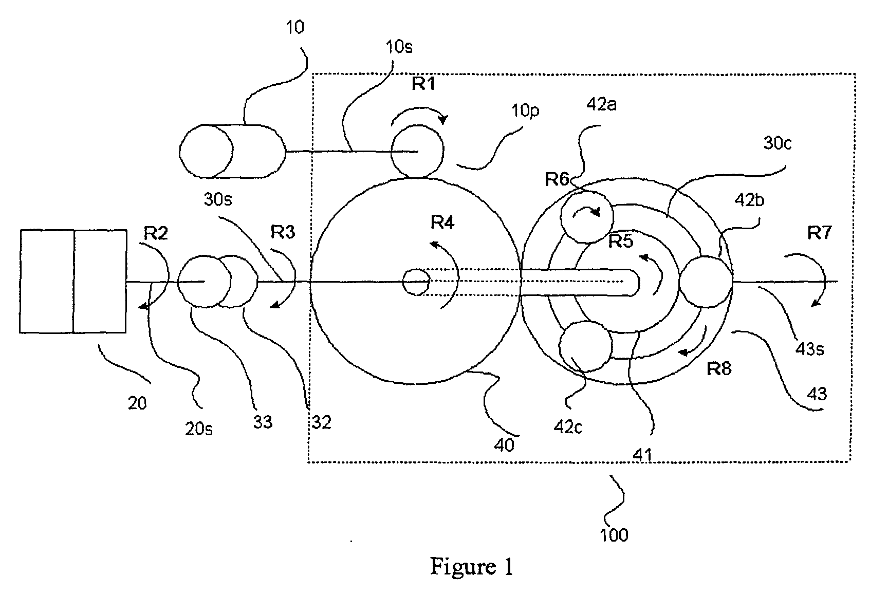
- Figure 1 is a schematic illustration a power combining apparatus according to an embodiment of the present invention.
- Figure 2 is a more detailed cross sectional view of a power combining apparatus according to an embodiment of the present invention wherein two variable power sources are utilized.
- Figure 3A is a top view schematic of the power combining apparatus embodied in a parallel hybrid electric truck configuration.
- Figure 3B is a more detailed schematic view of the output side of the gearbox assembly of Figure 3A.
- Figure 3C is a more detailed schematic view of the input side of the collection transmission box assembly of Figure 3A.
- Figure 4 is a graphical representation of the speed of rotation of each component in the planetary gear system through the different modes according to an aspect of the present invention.
- Figure 5 is a schematic cross sectional view of an in-line parallel hybrid electric vehicle transmission incorporating a power combining apparatus according to an alternate embodiment of the present invention.
- Figure 6 is a schematic cross sectional view of an in-line parallel hybrid electric vehicle transmission incorporating a power combining apparatus according to a second alternate embodiment of the present invention.
- Figure 7 is a schematic cross sectional view of an in-line parallel hybrid electric vehicle transmission incorporating a power combining apparatus according to a third alternate embodiment of the present invention.
- Figure 8 is a schematic cross sectional view of an in-line parallel hybrid electric vehicle transmission incorporating a power combining apparatus according to a fourth alternate embodiment of the present invention.
- Figure 9 is a schematic cross sectional view of an in-line parallel hybrid electric vehicle transmission incorporating a power combining apparatus according to a fifth alternate embodiment of the present invention.
-
- As described herein, the collection transmission system of the present invention utilizes a planetary gear set to combine and transmit power from multiple inputs through to a single output. The gear set is enclosed in a case that can accept the output shaft of one or more variable power supplies and an output shaft from a constant power source. The output of this system is in the form of a shaft that can be adapted to drive various loads. The entire system is supported through mounting sockets on the case.
- Referring now to the drawings, wherein like reference numerals indicate like parts, and in particular to Figure 1, there is shown a schematic illustration of a power combining
collection transmission system 100 according to an embodiment of the present invention. As shown in Figure 1, thesystem 100 comprises a planetary gear set comprising asun gear 41, aring gear 43 directly connected to an output shaft 43s, a plurality ofplanet gears carrier assembly 30c rotatably supporting the plurality ofplanet gears 42a-c journaled with thesun gear 41 andring gear 43. A torque transmitting arrangement comprisespinion gear 10p andbull gear 40.Bull gear 40 is operatively coupled to the sun gear and to thepinion gear 10p which acceptsshaft 10s ofvariable power source 10 such as a reversible electric motor for influencing rotation of the sun gear according to the rotation of the variable power supply shaft. This in turn influences rotation ofring gear 43 and output shaft 43s coupled thereto. Thecarrier assembly 30c of the planetary gear arrangement is operatively connected tocarrier shaft 30s which runs coaxial withsun gear 41. Thecarrier assembly 30c is selectively connectable toshaft 20s ofconstant power source 20 such as an internal combustion engine viaclutch mechanism 33 for selectively influencing rotation of the carrier assembly of the planetary gears and the ring gear, thereby influencing rotation of output drive shaft 43s. - As one can ascertain from the above description, the transmission system of Figure 1 preferably uses one or more reversible electric motors as its
variable power source 10. The motor is connected directly to the gear case and drives throughpinion 10p that meshes withsingle bull gear 40. Thebull gear 40 is fixed directly to and meshes withsun gear 41 of the planetary set. Theconstant power source 20 is preferably in the form of an internal combustion engine that runs at a constant speed with limited torque feedback.Constant power source 20 is connected to the carrier throughclutch mechanism 33. - Operation of the above system is as follows. In order to produce power at the output 43s of
collection transmission 100, an input power must be provided fromconstant power source 20,variable power source 10, or both. As shown in Figure 1,constant power source 20 transmits its power through itsshaft 20s toclutch mechanism 33 comprisingconventional clutch member 33 andbrake member 32 to thecarrier 30c of the planetary set. The clutch, which may be a fluid-operated clutch, and brake are conventional control devices used with power transmissions. In Figure 1, the rotation R2 of theshaft 20s ofconstant power supply 20 creates a rotation R3 ofcarrier shaft 30s. This rotation R3 is transmitted to thecarrier 30c viacarrier shaft 30s to produce rotation R8 which is combined with rotation R5 ofsun gear 41 to produce rotation R7. The power is then transmitted through thering gear 43 directly connected to output shaft 43s. In a preferred embodiment, the ratio between these components (i.e the carrier and the ring gear) is approximately a 1.3 to 1 decrease in torque. - The
variable power supply 10 transmits its power through itsshaft 10s to thepinion gear 10p into thebull gear 40 directly connected tosun gear 41. In Figure 1, a specific rotation R1 of the shaft ofvariable power supply 10 causes a rotation R4 of thebull gear 40 which is directly transmitted tosun gear 41. This rotation causes theplanet gears 42a-c to rotate in direction R6, thus creating the rotation R7 ofring gear 43. In a preferred embodiment, this results in a speed reduction of approximately 5:1 and an increase in torque. The input power is then transmitted throughplanet gears 42a-c toring gear 43 connected to the output. Preferably, the speed ratio between the sun gear and ring gear is approximately 3 to 1. - This system of the present invention can operate in three different modes, the first of which uses the variable power source to provide the total power output. With clutch 33 disengaged and
brake 32 engaged in the clutch/brake mechanism, it is possible to stop the rotation of theshaft 30s and thecarrier 30c by providing a defined amount of reaction torque dependent on the ratios of the gears in the planet set 42a-c and relative to the torque applied by the variable power supply. The power then moves through thebull gear 40 to thesun gear 41, then from thesun gear 41 through the planets to ringgear 43, which is directly connected to the output drive shaft 43s. - The second mode utilizes the
constant power supply 20 to provide the output power to drive shaft 43s. With thevariable power supply 10 producing enough torque on the system to stop thesun gear 41 from rotating, the power path for theconstant power supply 20 is isolated and the power is transmitted throughclutch mechanism 33 to thecarrier 30c. Thecarrier 30c cooperates withsun gear 41 to pass the power through theplanets 42a-c to thering gear 43 to drive output shaft 43s. In this mode the clutch is engaged and the brake disengaged so as to establish a drive path for transmitting the power fromconstant power source 20 to output drive shaft 43s through the combining planetary gear set. - The third mode of operation combines power contributions from both the
constant power supply 20 andvariable power supply 10. In this mode, the clutch 33 is engaged and thebrake 32 is off in the clutch/brake mechanism. The power then flows from each component as described in the previous two modes until they reach the planet set which splits the torque contributions for each depending on the assigned ratios. The speed of rotation of each component in the planetary gear system through the different modes is illustrated in Figure 4. - A further advantageous feature of the system according to the present invention is that the
variable power supply 10 is driven to a point of a synchronizing speed when the transmission changes modes. This allows the mode change point to be selected such that the majority of the power is supplied by the fixed speed ormechanical power source 20. The less efficient variable speed power source supplies a smaller percentage of the power but is still available to assist in situations where more power is required such as passing and climbing grades at high speed. This enables the system to run at its most efficient power transmission point where the system spends most of its time and provides a means of generating the torque required to accelerate the vehicle without using a multi-gear ratio transmission. - In a particular embodiment, when the vehicle is accelerated to a predetermined speed, for example, 52mph, the brake holding the
carrier 30c fixed is released. This allows the carrier components to spin up to speed to match the engine output shaft. This is accomplished by driving the electric motor(s) to a synchronizing speed for synchronizing with the fixed power source. In a particular embodiment, this is accomplished by transitioning the electric motor(s) from a given speed/rotation (e.g. 15000 rpm) to a second speed/rotation (e.g. -1300 rpm), for example, to limit clutch slippage. When the motor(s) reach the synchronizing speed, the carrier is at the engine operating speed. The ring gear is connected to the output drive shaft and to the axles via a final drive such that the vehicle momentum is used to turn the ring gear, thereby helping to synchronize the speed. Once the traction motor(s) are at the synchronizing speed, the clutch can be locked to provide a direct drive between the engine and the rear axle. The carrier, the ring gear and the motor are linked via the planetary gear set so that knowledge of two of the components of the system enables one to determine the third component. - As one can ascertain, three major events occur during the transfer between the source of power from variable to mechanical. First, the brake in the clutch/brake mechanism between the constant power source and the planetary gear set is disengaged. Second, the variable power source is driven to a synchronizing speed so that the power before and after the transfer is as close to the same value as possible. Finally, the constant power supply is speed synchronized with the carrier of the planetary set as closely as possible to limit clutch slip as the clutch in the aforementioned clutch/brake mechanism is engaged.
- The collection transmission can be employed with one or more
variable power sources 10 connected to thebull gear 40 so long as the power sources are matched such that the output speeds are synchronous. Figure 2 illustrates such a configuration. As shown in Figure 2, twoelectric traction motors bull gear 40 via pinions 10pa and 10pb, respectively and speed synchronized to provide the variable power source to thecollection transmission 100.Internal combustion engine 20, coupled toconventional gear box 24, is used to provide power for theelectric motors generator 22 as well as providing a direct or parallel path of power to the final drive of the vehicle via drive shaft 43s. The gear case can be made of a suitable material such as a metal, for example, that will be strong enough to support the internal components and have mounting sockets located such that the gear case can be attached in a known manner to a stationary object. Preferably, the gear case housing the collection transmission system is bolted directly to the engine. - In stop and go traffic, a parallel HEV that incorporates the present invention may, for example, operate in the first "electrical only" mode of operation approximately 33% of the time. The generators are used to supply power to the motor or motors. A battery or batteries (not shown) may also be used and coupled to the electric motors to absorb power during acceleration. During deceleration, the energy normally dissipated as heat in the brakes may be re-routed and stored in the batteries thereby providing additional fuel economy, less engine cycling and enhanced efficiency. Moreover, in conventional transmission systems such as a typical eight speed transmission, eight different gear ratios are needed, with only the top two gear ratios typically used for highway travel. The remaining gear ratios are used in stop and go traffic to accelerate/decelerate the vehicle. In the present invention, the electric motors may be used to accelerate the vehicle up to highway speeds (e.g. about 50 mph) before switching over to a parallel combination of electrical and mechanical power, and then ultimately transitioning completely over to mechanical power.
- Figure 3A shows a block diagram of the embodiment shown in Figure 2 incorporated within a parallel hybrid electric vehicle configuration such as a line haul truck. As shown in Figure 3A,
internal combustion engine 20 such as a diesel engine is operatively coupled toclutch mechanism 33 viagear box 24 andshaft 20s.Gear box 24 also operatively connectsinternal combustion engine 20 togenerator 22. The gear box operates in conventional fashion by having an input for the IC engine output and providing an output forgenerator 22 and an output forshaft 20s upstream ofclutch 33 via a gear reduction mechanism. Reversibleelectric motors inputs 54 and 56 (see Figure 3B) ofcollection transmission system 100. The system includes input 52 (see Figure 3C) coupled toclutch mechanism 33 viacarrier shaft 30s for receiving power from the constant power source. The output 58 (see Figure 3C) ofcollection transmission system 100 is adapted to accommodate output drive shaft 43s for connection to final drive 55. Final drive 55 is in turn operatively connected via differential 99 towheel axle shaft 72 for drivingvehicle wheels 13. In a preferred embodiment, thevariable power source 10 represented byelectric motors - Figures 5-9 illustrate schematic diagrams of alternative embodiments of the power combining apparatus of the present invention. These embodiments employ configurations that utilize coaxial shafts that create an inline envelope for the entire system. This is advantageous in that these configurations provide a package that will fit into the space occupied by conventional vehicle transmission systems, thereby making it easier for manufacturers to integrate a hybrid drive system into a current production vehicle. The embodiment illustrated in Figure 5 uses a
variable power source 10 that is tuned to provide the torque and speed characteristics required to produce the desired output from the planetary gearbox. The embodiments depicted in Figures 6-9 utilize a reduction scheme to incorporate a variable power supply for adaptation to a particular application. Each of these figures illustrates a hybrid electric power train depicting a generator, motor, and collection transmission. - The embodiment shown in Figure 5 illustrates the in-line configuration where the
rotor shaft 11 of a suitable motor is mounted rigidly to thesun gear 41 of the collection transmission or combininggearbox 100. A singlehollow rotor motor 10 is used to pass thecarrier shaft 30s directly through thesun gear 41 without the need for pinion and bull gears. Thegenerator 22 includesrotor 23 andstator 25. Therotor 23 of the generator is rigidly mounted to theoutput shaft 20s from the torsional damper (not shown) on the engine.Clutch 30 is used to engage and disengage thecarrier drive shaft 30s, andbrake 32 has been incorporated to ground thecarrier 30c to the external wall of the transmission. - Figures 6, 7, and 8 provide additional embodiments for accommodating a motor that is not optimally sized to the vehicle horsepower requirements associated with a particular HEV. The embodiment shown in Figure 6 is similar to Figure 5 but utilizes an additional
planetary reduction assembly 60 that includes aring gear 61 fixed to the external wall of the casing,planetary gears 62a-62c journaled tocarrier 64, andsun gear 63 coupled to therotor shaft 11 ofmotor 10. Themotor rotor 11 drives into theplanetary reduction assembly 60 through thesun gear 63. Thecarrier 64 of the planetary reduction assembly drives thesun gear 41 of thecollector transmission 100. - An alternative embodiment shown in Figure 7 is similar to the previous embodiment shown in Figure 6 in that it uses a planetary reduction gear set 60 with a grounded
carrier 64 to produce acceptable speed input for the combininggearbox 100. - The embodiments shown in Figures 8 and 9 use planetary gearbox 97 to act as a speed increaser. This is accomplished in two ways. By driving the
motor rotor 11 into thecarrier 64 and grounding thering gear 61 it is possible to use a motor turning at a lower speed to drive thesun gear 63 to drive the collectortransmission sun gear 41. This is shown in figure 8. As shown in Figure 9, if themotor rotor 11 is used to drive thering gear 61 and thecarrier 64 is grounded a slower motor can be used to drive the combining gearbox. The different embodiments do not affect the modes of operation and as stated previously will allow for a more traditional installation in a vehicle. - Although the invention has been described and pictured in preferred form with a certain degree of particularity, it is understood that the present disclosure of the preferred form has been made only by way of example, and that numerous changes in the details of construction and combination and arrangement of parts may be made without departing from the spirit and scope of the invention as hereinafter claimed. It is intended that the patent shall cover by suitable expression in the appended claims, whatever features of patentable novelty exist in the invention disclosed.
Claims (21)
- A vehicle transmission system adapted for receiving inputs from variable and constant power sources for driving an output shaft comprising:a combining planetary gear arrangement having a plurality of members and operatively coupled to a rotatable shaft of said variable power source, a rotatable shaft of said constant power source, and to said output shaft;a torque transmitting arrangement coupled to a member of said combining planetary gear arrangement and responsive to said variable power source for influencing rotation of said output shaft according to rotation of said shaft of said variable power source; anda clutch for selectively connecting the constant power source with another member of the combining planetary gear arrangement for establishing a drive path between said constant power source and said combining planetary gear arrangement for influencing rotation of the output shaft according to rotation of the constant power source shaft.
- The system according to claim 1, wherein said plurality of members of said combining planetary gear arrangement include a sun gear, a ring gear, a plurality of planet gears, and a carrier assembly rotatably supporting the plurality of planet gears journaled with said sun and ring gears.
- The system according to claims 1 or 2, wherein said ring gear is directly coupled to said output shaft.
- The system according to any one of claims 1-3, wherein said member coupled to said torque transmitting arrangement is said sun gear.
- The system according to any one of claims 1-4, wherein said another member of said combining planetary gear arrangement is said carrier.
- The system according to any one of claims 1-5, wherein said torque transmitting arrangement comprises a bull gear connected to a pinion gear.
- The system according to any one of claims 1-6, wherein said variable power source comprises an at least one electric motor.
- The system according to claim 6, wherein said wherein said at least one electric motor is a reversible motor.
- The system according to any one of claims 1-8, wherein said constant power source comprises an internal combustion engine operating at a constant speed.
- The system according to any one of claims 1-9, further comprising a brake for selectively grounding said another member of said planetary gear arrangement and said constant power source connected therewith for preventing operation of said output shaft from influence by rotation of said shaft of said constant power supply.
- The system according to claim 10, wherein said system is operative in a first mode such that said output shaft is driven by said mechanical power source, in a second mode such that said output shaft is driven by said variable power source, and in a third mode such that said output shaft is driven by the combination of said variable and constant power sources.
- The system according to claim 9, wherein said variable power supply is driven to substantially a synchronizing speed to cause said transmission system to change modes.
- A vehicle transmission system comprising:wherein the carrier assembly of said planetary gear arrangement is selectively connectable to said constant power source for selectively influencing rotation of said carrier assembly of said planetary gears and said ring gear, to thereby influence rotation of said output shaft.a planetary gear set comprising a sun gear, a ring gear connected to an output shaft, a plurality of planet gears, and a carrier assembly rotatably supporting the plurality of planet gears journaled with said sun and ring gears; anda torque transmitting arrangement coupled to said sun gear and to the shaft of said variable power source for influencing rotation of said sun gear according to the rotation of said variable power supply shaft for causing rotation of said sun gear, thereby influencing rotation of said ring gear and said output shaft;
- The system according to claim 13, wherein said torque transmitting arrangement comprises a pinion gear connected to a bull gear.
- The system according to claim 14, wherein said bull gear is directly connected to said sun gear.
- The system according to any one of claims 13-15, further comprising a clutch for selectively connecting the carrier assembly of said planetary gear arrangement to said constant power source.
- The system according to claim 16, further comprising a brake for selectively grounding said carrier assembly and said constant power source connected therewith for preventing operation of said output shaft from influence by rotation of said shaft of said constant power source.
- A vehicle transmission system having a drive shaft which can be driven continuously or at varying speeds and operable in a first mechanical mode, a second electrical mode, or a third combined mode of operation, comprising:a combining planetary gear arrangement having a plurality of members and operatively coupled to a rotatable shaft of a variable power source, a rotatable shaft of a constant power source, and to said output drive shaft;a clutch and brake mechanism operable in said first and third modes for connecting said constant power source with a member of said combining planetary gear arrangement for establishing a drive path between said combining planetary gear arrangement and said constant power source for influencing rotation of said output shaft according to a rotation direction of the constant power source shaft, and in said second mode for grounding said member of said combining planetary gear arrangement for preventing rotation of said output drive shaft from being influenced by the constant power source; anda torque transmitting arrangement coupled to another member of said combining planetary gear arrangement and responsive to said variable power source for influencing rotation of said output shaft according to a rotation direction of said shaft of said variable power source in said second and third modes of operation, and in said first mode of operation, for producing sufficient torque to prevent rotation of said another member for preventing rotation of said output drive shaft from being influenced by the variable power source.
- The system according to claim 18, wherein said variable power supply is driven to substantially a synchronizing speed to cause said transmission system to change modes.
- The system according to claims 18 or 19, wherein said planetary gear arrangement comprises a sun gear, a ring gear connected to said output shaft, a plurality of planet gears, and a carrier assembly rotatably supporting the plurality of planet gears journaled with said sun and ring gears.
- The system according to claim 20, wherein said torque transmitting arrangement comprises a pinion connected to a bull gear, and wherein said variable power source comprises one or more reversible electric motors speed synchronized and connected through said pinion and bull gear to said combining planetary gear arrangement via said sun gear.
Applications Claiming Priority (2)
| Application Number | Priority Date | Filing Date | Title |
|---|---|---|---|
| US09/782,836 US6455947B1 (en) | 2001-02-14 | 2001-02-14 | Power combining apparatus for hybrid electric vehicle |
| US782836 | 2007-07-25 |
Publications (3)
| Publication Number | Publication Date |
|---|---|
| EP1232892A2 true EP1232892A2 (en) | 2002-08-21 |
| EP1232892A3 EP1232892A3 (en) | 2005-10-26 |
| EP1232892B1 EP1232892B1 (en) | 2009-02-25 |
Family
ID=25127319
Family Applications (1)
| Application Number | Title | Priority Date | Filing Date |
|---|---|---|---|
| EP01130079A Expired - Lifetime EP1232892B1 (en) | 2001-02-14 | 2001-12-18 | Power combining apparatus for hybrid electric vehicle |
Country Status (13)
| Country | Link |
|---|---|
| US (2) | US6455947B1 (en) |
| EP (1) | EP1232892B1 (en) |
| JP (2) | JP3949966B2 (en) |
| KR (1) | KR100803533B1 (en) |
| CN (1) | CN1289327C (en) |
| AR (1) | AR032234A1 (en) |
| AT (1) | ATE423697T1 (en) |
| BR (2) | BR0216068B1 (en) |
| CA (1) | CA2365053C (en) |
| DE (1) | DE60137753D1 (en) |
| ES (1) | ES2321275T3 (en) |
| MX (1) | MXPA02001602A (en) |
| TW (1) | TW519525B (en) |
Cited By (11)
| Publication number | Priority date | Publication date | Assignee | Title |
|---|---|---|---|---|
| WO2005090108A1 (en) * | 2004-03-15 | 2005-09-29 | Deere & Company | Drive system for a vehicle |
| WO2007031399A1 (en) * | 2005-09-15 | 2007-03-22 | Deere & Company | Drive system for an agricultural or industrial utility vehicle |
| WO2007031397A1 (en) * | 2005-09-15 | 2007-03-22 | Deere & Company | Drive system for an agricultural or industrial utility vehicle and method for operating a drive system |
| FR3038278A1 (en) * | 2015-06-30 | 2017-01-06 | Ifp Energies Now | HYBRID VEHICLE COMPRISING TORQUE BREAKING TO SINGLE PROPULSION MODE CHANGES |
| WO2017100258A1 (en) * | 2015-12-07 | 2017-06-15 | Dana Heavy Vehicle Systems Group, Llc | Distributed drivetrain architectures for commercial vehicles with a hybrid electric powertrain and dual range disconnect axles |
| US10486521B2 (en) | 2015-12-07 | 2019-11-26 | Dana Heavy Vehicle Systems Group, Llc | Distributed drivetrain architectures for commercial vehicles with a hybrid electric powertrain |
| US10807466B1 (en) | 2016-03-28 | 2020-10-20 | Dana Heavy Vehicle Systems Group, Llc | Electric drivetrain axles with multi-speed gearboxes |
| US10857881B2 (en) | 2016-11-15 | 2020-12-08 | Dana Heavy Vehicle Systems Group, Llc | Electric drivetrain for a tandem drive axle |
| US11054009B2 (en) | 2016-03-28 | 2021-07-06 | Dana Heavy Vehicle Systems Group, Llc | Single electric motor drive axle with multiple ratios |
| EP4242029A1 (en) * | 2022-03-11 | 2023-09-13 | Kubota Corporation | Work vehicle |
| JP2023132982A (en) * | 2022-03-11 | 2023-09-22 | 株式会社クボタ | work vehicle |
Families Citing this family (79)
| Publication number | Priority date | Publication date | Assignee | Title |
|---|---|---|---|---|
| IT1309008B1 (en) * | 1999-02-24 | 2002-01-15 | Vf Venieri S P A | PROPULSION GROUP FOR FOUR-WHEEL ELECTRIC VEHICLES FOR EARTH-MOVING AND AGRICULTURE |
| JP3578451B2 (en) * | 2001-07-23 | 2004-10-20 | 日産自動車株式会社 | Drive |
| US7223200B2 (en) * | 2001-10-22 | 2007-05-29 | Toyota Jidosha Kabushiki Kaisha | Hybrid-vehicle drive system and operation method with a transmission |
| EP1918150B1 (en) * | 2001-12-26 | 2012-11-21 | Toyota Jidosha Kabushiki Kaisha | Drive apparatus for hybrid vehicle |
| AU2003209341A1 (en) * | 2002-01-18 | 2003-09-02 | Dennis W. Aukon | Hydroelectric generator |
| US6962545B2 (en) * | 2002-09-23 | 2005-11-08 | Bae Systems Onctrols | Multi-range parallel-hybrid continuously variable transmission |
| US7315090B2 (en) * | 2003-02-12 | 2008-01-01 | Tai-Her Yang | Series-parallel dual power hybrid driving system |
| US7196430B2 (en) * | 2003-02-12 | 2007-03-27 | Tai-Her Yang | Partial-powered series hybrid driving system |
| DE10315937A1 (en) * | 2003-04-08 | 2004-11-11 | Deere & Company, Moline | Drive device for driving accessories for a vehicle |
| CA2430157A1 (en) * | 2003-05-30 | 2004-11-30 | Tm4 Inc. | Electric vehicle traction system |
| US7101307B2 (en) * | 2003-07-14 | 2006-09-05 | Luke W. Clauson | Methods and devices for altering the transmission ratio of a drive system |
| JP3887361B2 (en) * | 2003-08-18 | 2007-02-28 | 本田技研工業株式会社 | Hybrid vehicle |
| JP4000529B2 (en) * | 2003-12-10 | 2007-10-31 | アイシン・エィ・ダブリュ株式会社 | Hybrid drive device |
| US7500687B2 (en) * | 2004-01-31 | 2009-03-10 | Lockheed Martin Corporation | Vehicle suspension systems |
| JP3812570B2 (en) * | 2004-02-25 | 2006-08-23 | 日産自動車株式会社 | Drive device for hybrid vehicle |
| JP2005323425A (en) * | 2004-05-07 | 2005-11-17 | Denso Corp | Vehicle power generation system |
| US7264071B2 (en) * | 2004-05-12 | 2007-09-04 | General Motors Corporation | Hybrid powertrain |
| US7465251B2 (en) * | 2004-07-10 | 2008-12-16 | Lingling Zhang | Hybrid electric vehicle |
| US7766778B2 (en) * | 2004-09-14 | 2010-08-03 | Toyota Jidosha Kabushiki Kaisha | Drive device for vehicle |
| WO2006035981A1 (en) * | 2004-09-27 | 2006-04-06 | Toyota Jidosha Kabushiki Kaisha | Drive device for vehicle |
| DE112005002356B4 (en) * | 2004-09-27 | 2018-09-06 | Toyota Jidosha Kabushiki Kaisha | Drive unit for a vehicle |
| JP4059876B2 (en) * | 2004-10-14 | 2008-03-12 | トヨタ自動車株式会社 | Hybrid drive device |
| WO2006090796A1 (en) | 2005-02-24 | 2006-08-31 | Mitsubishi Heavy Industries, Ltd. | Torque transmission structure, traction drive transmission device, and steering device for vehicle |
| KR101028402B1 (en) | 2005-04-11 | 2011-04-13 | 현대다이모스(주) | Power train of hybrid electric vehicle |
| KR101028401B1 (en) | 2005-04-11 | 2011-04-13 | 현대다이모스(주) | Power train of hybrid electric vehicle |
| KR101028400B1 (en) | 2005-04-11 | 2011-04-13 | 현대다이모스(주) | Hybrid-driven continuously variable transmission and hybrid vehicle |
| KR101085977B1 (en) | 2005-04-12 | 2011-11-22 | 현대다이모스(주) | Power train of hybrid electric vehicle |
| KR101085976B1 (en) | 2005-04-12 | 2011-11-22 | 현대다이모스(주) | Power train of hybrid electric vehicle |
| US7497286B2 (en) * | 2005-07-29 | 2009-03-03 | Borgwarner Inc. | Auxiliary electric drive assembly |
| KR100642596B1 (en) * | 2005-08-24 | 2006-11-10 | 다이모스(주) | Power Train of Hybrid Electric Vehicle |
| JP4234710B2 (en) * | 2005-10-26 | 2009-03-04 | トヨタ自動車株式会社 | Electric vehicle drive control device and control method thereof |
| US7513349B2 (en) * | 2005-11-30 | 2009-04-07 | Tm4 Inc. | Multi-position clutch |
| KR100726222B1 (en) * | 2006-01-04 | 2007-06-11 | 현대자동차주식회사 | Power train for continuously variable speed and planetary gear hybrid vehicle |
| JP4972988B2 (en) * | 2006-05-02 | 2012-07-11 | 日産自動車株式会社 | Hybrid vehicle transmission state switching control device |
| US7393065B2 (en) * | 2006-06-01 | 2008-07-01 | Lockheed Martin Corporation | Redundant braking system |
| CN100567768C (en) * | 2006-07-13 | 2009-12-09 | 同济大学 | Powertrain for Hybrid Vehicles |
| KR100802692B1 (en) | 2006-08-08 | 2008-02-12 | 현대자동차주식회사 | Power Train of Hybrid Electric Vehicle |
| US7594868B1 (en) | 2006-08-25 | 2009-09-29 | Sauer-Danfoss Inc. | Split-power transmission with mode shift |
| US20080066613A1 (en) * | 2006-09-15 | 2008-03-20 | Lockheed Martin Corporation | Perforated hull for vehicle blast shield |
| US20080173167A1 (en) | 2006-09-15 | 2008-07-24 | Armor Holdings | Vehicular based mine blast energy mitigation structure |
| KR100774657B1 (en) | 2006-10-13 | 2007-11-08 | 현대자동차주식회사 | Hybrid train powertrain |
| KR100820401B1 (en) | 2006-10-18 | 2008-04-08 | 현대자동차주식회사 | Hybrid train powertrain |
| KR100820402B1 (en) * | 2006-10-23 | 2008-04-08 | 현대자동차주식회사 | Hybrid powertrain |
| KR100932285B1 (en) * | 2007-07-09 | 2009-12-16 | 하태환 | Power train |
| US8197384B2 (en) * | 2007-07-09 | 2012-06-12 | Toyota Jidosha Kabushiki Kaisha | Engine start-up device for hybrid vehicle power transmitting device |
| US7980340B2 (en) * | 2007-12-27 | 2011-07-19 | Byd Co. Ltd. | Hybrid vehicle having power assembly arranged transversely in engine compartment |
| DE102008051199A1 (en) * | 2008-10-14 | 2010-04-29 | Maamar Bouchareb | Method and arrangement for fan control |
| JP5432279B2 (en) * | 2008-12-08 | 2014-03-05 | ルノー・トラックス | Method for controlling the operation of a hybrid vehicle and a vehicle adapted to the method |
| JP2012519809A (en) | 2009-03-06 | 2012-08-30 | ディーティーアイ グループ ビー.ブイ. | Electric or hybrid drive transmission |
| US8414436B2 (en) * | 2009-04-30 | 2013-04-09 | GM Global Technology Operations LLC | Hybrid powertrain and method of operating same |
| US9550412B2 (en) * | 2009-05-21 | 2017-01-24 | Mtu America Inc. | Power generation system and method for assembling the same |
| US8167062B2 (en) * | 2009-05-21 | 2012-05-01 | Tognum America Inc. | Power generation system and method for assembling the same |
| IT1395448B1 (en) * | 2009-09-03 | 2012-09-21 | Ferrari Spa | METHOD OF STARTING A THERMAL ENGINE OF A VEHICLE WITH A HYBRID PROPULSION |
| TWI401858B (en) * | 2009-10-05 | 2013-07-11 | Chin Lien Hong | Electric vehicle and its energy saving module power plant |
| WO2012009744A1 (en) * | 2010-07-22 | 2012-01-26 | Nt Consulting International Pty Limited | Vehicle drivetrain |
| WO2012053361A1 (en) * | 2010-10-21 | 2012-04-26 | 本田技研工業株式会社 | Drive device for hybrid vehicle |
| WO2013005593A1 (en) * | 2011-07-01 | 2013-01-10 | ジヤトコ株式会社 | Vehicle control device |
| JP2013147235A (en) * | 2012-01-23 | 2013-08-01 | Hino Motors Ltd | Driving device for hybrid vehicle |
| CA2810938C (en) | 2012-03-26 | 2018-08-14 | Enedym Inc. | Powertrain system for hybrid vehicles having compound and split modes of operation |
| US9421855B2 (en) | 2012-03-26 | 2016-08-23 | Mcmaster University | Powertrain system for hybrid vehicles having multiple modes of operation |
| DE112014001387B4 (en) * | 2013-03-15 | 2017-07-20 | Remy Technologies Llc | Generator / engine start arrangement with a gear reduction system |
| JP2016533960A (en) * | 2013-08-29 | 2016-11-04 | ケーピーアイティ テクノロジーズ リミテッド | Retrofit system for converting a vehicle into one of a hybrid electric vehicle and an electric vehicle (EV) |
| FR3014773B1 (en) * | 2013-12-17 | 2017-05-19 | Ifp Energies Now | POWERTRAIN UNIT WITH A VARIABLE SPEED TRANSMISSION DEVICE, ESPECIALLY FOR A HYBRID VEHICLE. |
| KR101550627B1 (en) | 2014-01-02 | 2015-09-07 | 현대자동차 주식회사 | Power transmission system of hybrid electric vehicle |
| CN105082974B (en) * | 2014-04-16 | 2017-12-12 | 比亚迪股份有限公司 | Power drive system and the vehicle with the power drive system |
| DE102014016172A1 (en) * | 2014-11-03 | 2016-05-04 | Audi Ag | Drive device for a hybrid-powered motor vehicle |
| US20170126159A1 (en) * | 2015-10-29 | 2017-05-04 | Hamilton Sundstrand Corporation | Generation system with braking mechanism |
| US10293808B2 (en) | 2017-03-03 | 2019-05-21 | Toyota Motor Engineering & Manufacturing North America, Inc. | Constant power control |
| KR101886387B1 (en) * | 2017-06-09 | 2018-08-09 | (주)젠아트 | Rotating apparatus capable of rapid accelerating having high torque |
| US10619707B2 (en) * | 2017-09-28 | 2020-04-14 | The Regents Of The University Of Michigan | Multi-mode power split hybrid transmission with two planetary gear mechanisms |
| CN108006170A (en) * | 2017-12-04 | 2018-05-08 | 安徽未来机电科技有限公司 | A kind of planetary reduction gear of multi-change speed |
| DE102019208479A1 (en) * | 2019-06-11 | 2020-12-17 | Zf Friedrichshafen Ag | Transmission for a motor vehicle |
| CN111845317B (en) * | 2020-07-29 | 2022-07-19 | 重庆青山工业有限责任公司 | Hybrid power system |
| CN112696468A (en) * | 2020-12-25 | 2021-04-23 | 中国船舶重工集团公司第七0三研究所 | Horizontal eccentric external meshing and planetary compound transmission loading device |
| CN114475217B (en) * | 2022-03-25 | 2023-10-10 | 中国重汽集团济南动力有限公司 | A three-power source coupling hybrid system suitable for heavy-duty trucks |
| CN116461318B (en) * | 2023-04-24 | 2025-09-02 | 江苏大学 | A high-horsepower hybrid tractor drive system and control method |
| CN117639375B (en) * | 2023-11-17 | 2025-01-24 | 内蒙古科技大学 | A permanent magnet synchronous generator with built-in rotor |
| US12313153B1 (en) | 2024-01-11 | 2025-05-27 | Dana Heavy Vehicle Systems Group, Llc | Planetary pinion input electric drive unit |
| US20250233478A1 (en) * | 2024-01-11 | 2025-07-17 | Dana Heavy Vehicle Systems Group, Llc | Planetary pinion input electric drive unit |
Family Cites Families (46)
| Publication number | Priority date | Publication date | Assignee | Title |
|---|---|---|---|---|
| US4588040A (en) | 1983-12-22 | 1986-05-13 | Albright Jr Harold D | Hybrid power system for driving a motor vehicle |
| DE3625141A1 (en) | 1986-07-25 | 1988-02-04 | Man Nutzfahrzeuge Gmbh | DRIVING DEVICE FOR A VEHICLE WITH EMERGENCY DEVICE UNIT |
| US4862009A (en) | 1988-03-22 | 1989-08-29 | General Electric Company | Combined electric starter and alternator system using a permanent magnet synchronous machine |
| JP3083310B2 (en) | 1990-01-26 | 2000-09-04 | 三菱電機株式会社 | Engine power transmission with start function |
| US5193634A (en) | 1990-03-08 | 1993-03-16 | Piaggio Veicoli Europei S.P.A. | Hybrid propulsion system for vehicles, in particular for road vehicles |
| US5120282A (en) | 1990-10-16 | 1992-06-09 | Fjaellstroem Bengt | Vehicle transmission system |
| DE4202083C2 (en) | 1992-01-25 | 1994-01-20 | Daimler Benz Ag | Hybrid drive for a motor vehicle |
| JP3221118B2 (en) | 1992-11-27 | 2001-10-22 | 株式会社エクォス・リサーチ | Power transmission device for hybrid vehicle |
| US5509491A (en) * | 1994-04-18 | 1996-04-23 | General Motors Corporation | Dual-motor electric drive system for vehicles |
| JP3291916B2 (en) | 1994-06-06 | 2002-06-17 | 株式会社エクォス・リサーチ | Hybrid vehicle |
| US5558175A (en) | 1994-12-13 | 1996-09-24 | General Motors Corporation | Hybrid power transmission |
| JP3414059B2 (en) | 1995-07-19 | 2003-06-09 | アイシン・エィ・ダブリュ株式会社 | Vehicle drive system |
| US5577973A (en) | 1995-07-20 | 1996-11-26 | General Motors Corporation | Two-mode, split power, electro-mechanical transmission |
| US5881559A (en) | 1995-07-28 | 1999-03-16 | Isuzu Ceramics Research Institute Co., Ltd. | Hybrid electric vehicle |
| JP3409523B2 (en) | 1995-08-02 | 2003-05-26 | アイシン・エィ・ダブリュ株式会社 | Control device for vehicle drive unit |
| US5603671A (en) | 1995-08-08 | 1997-02-18 | General Motors Corporation | Three prime mover bus transmission |
| JP3610687B2 (en) * | 1995-12-12 | 2005-01-19 | トヨタ自動車株式会社 | Start control device for internal combustion engine and control method thereof |
| US5637987A (en) | 1995-12-18 | 1997-06-10 | General Motors Corporation | Regenerative vehicle launch |
| US6155364A (en) * | 1996-02-21 | 2000-12-05 | Toyota Jidosha Kabushiki Kaisha | Hybrid drive system wherein planetary gear mechanism is disposed radially inwardly of stator coil of motor/generator |
| JPH09277847A (en) * | 1996-04-11 | 1997-10-28 | Toyota Motor Corp | Engine brake control device for hybrid vehicle |
| US5982045A (en) * | 1996-04-19 | 1999-11-09 | Toyota Jidosha Kabushiki Kaisha | Hybrid vehicle drive system adapted to prevent concurrent mode change and transmission shifting or torque distribution ratio change |
| US5669842A (en) * | 1996-04-29 | 1997-09-23 | General Motors Corporation | Hybrid power transmission with power take-off apparatus |
| US5813488A (en) * | 1996-06-14 | 1998-09-29 | Deere & Company | Electric wheel drive for a utility vehicle |
| US5730676A (en) * | 1996-10-22 | 1998-03-24 | General Motors Corporation | Three-mode, input-split hybrid transmission |
| DE59710076D1 (en) * | 1996-11-30 | 2003-06-18 | Volkswagen Ag | Continuously adjustable step change gear |
| JP3536581B2 (en) | 1997-04-16 | 2004-06-14 | 日産自動車株式会社 | Power generation control device for hybrid electric vehicle |
| DE69821750T2 (en) * | 1997-04-18 | 2006-06-22 | Transport Energy Systems Pty. Ltd., Holland Park | Hybrid drive system for use in vehicle operation |
| JP3354074B2 (en) | 1997-04-25 | 2002-12-09 | ジヤトコ株式会社 | Control device for parallel hybrid vehicle |
| JP3775012B2 (en) * | 1997-08-29 | 2006-05-17 | アイシン・エィ・ダブリュ株式会社 | Hybrid drive device for vehicle |
| JP3777751B2 (en) * | 1997-10-22 | 2006-05-24 | トヨタ自動車株式会社 | Engine starting and power generator |
| US5869950A (en) | 1997-10-30 | 1999-02-09 | Lockheed Martin Corp. | Method for equalizing the voltage of traction battery modules of a hybrid electric vehicle |
| US5950752A (en) | 1997-11-21 | 1999-09-14 | Lockheed Martin Corp. | Heating system for a hybrid electric vehicle |
| US5929595A (en) | 1997-11-21 | 1999-07-27 | Lockheed Martin Corporation | Hybrid electric vehicle with traction motor drive allocated between battery and auxiliary source depending upon battery charge state |
| US5910722A (en) | 1997-11-21 | 1999-06-08 | Lockheed Martin Corp. | Hybrid electric vehicle with reduced auxiliary power to batteries during regenerative braking |
| US5959420A (en) | 1997-12-01 | 1999-09-28 | Chrysler Corporation | Heat engine and electric motor torque distribution strategy for a hybrid electric vehicle |
| US5943918A (en) | 1997-12-01 | 1999-08-31 | Chrysler Corporation | Powertrain system for a hybrid electric vehicle |
| WO1999029533A1 (en) | 1997-12-05 | 1999-06-17 | Toyota Jidosha Kabushiki Kaisha | Hybrid driver |
| US5935035A (en) | 1998-06-24 | 1999-08-10 | General Motors Corporation | Electro-mechanical powertrain |
| US6022048A (en) | 1998-07-02 | 2000-02-08 | Navistar International Transportation Corp | Hybrid electric vehicle drive motor mounting module |
| JP3870576B2 (en) * | 1998-09-07 | 2007-01-17 | トヨタ自動車株式会社 | Hybrid drive device |
| WO2000032433A1 (en) | 1998-12-01 | 2000-06-08 | Hitachi, Ltd. | Drive device and vehicle |
| US6592484B1 (en) | 1999-08-09 | 2003-07-15 | Gregory A. Schultz | Transmission gearbox for parallel hybrid electric vehicles |
| JP3458795B2 (en) | 1999-10-08 | 2003-10-20 | トヨタ自動車株式会社 | Hybrid drive |
| JP3327262B2 (en) | 1999-10-08 | 2002-09-24 | トヨタ自動車株式会社 | Reverse travel device for vehicles |
| US20020003610A1 (en) * | 2000-06-26 | 2002-01-10 | Samsung Electro-Mechanics Co., Ltd. | Projection type display system using a polarizing beam splitter |
| US6491599B1 (en) | 2000-09-15 | 2002-12-10 | General Motors Corporation | Two-mode, compound-split, electro-mechanical, vehicular transmission particulary adapted for track-laying vehicles |
-
2001
- 2001-02-14 US US09/782,836 patent/US6455947B1/en not_active Ceased
- 2001-12-07 TW TW090130381A patent/TW519525B/en not_active IP Right Cessation
- 2001-12-17 CA CA002365053A patent/CA2365053C/en not_active Expired - Lifetime
- 2001-12-18 AT AT01130079T patent/ATE423697T1/en not_active IP Right Cessation
- 2001-12-18 EP EP01130079A patent/EP1232892B1/en not_active Expired - Lifetime
- 2001-12-18 ES ES01130079T patent/ES2321275T3/en not_active Expired - Lifetime
- 2001-12-18 DE DE60137753T patent/DE60137753D1/en not_active Expired - Lifetime
- 2001-12-28 KR KR1020010086639A patent/KR100803533B1/en not_active Expired - Fee Related
-
2002
- 2002-01-08 JP JP2002001153A patent/JP3949966B2/en not_active Expired - Fee Related
- 2002-01-09 AR ARP020100057A patent/AR032234A1/en active IP Right Grant
- 2002-01-22 BR BRPI0216068-4A patent/BR0216068B1/en not_active IP Right Cessation
- 2002-01-22 BR BRPI0200161-6A patent/BR0200161B1/en not_active IP Right Cessation
- 2002-02-10 CN CNB021046689A patent/CN1289327C/en not_active Expired - Lifetime
- 2002-02-14 MX MXPA02001602A patent/MXPA02001602A/en active IP Right Grant
-
2007
- 2007-01-18 JP JP2007009426A patent/JP2007182223A/en not_active Withdrawn
- 2007-02-13 US US11/705,797 patent/USRE41034E1/en not_active Expired - Lifetime
Non-Patent Citations (1)
| Title |
|---|
| None |
Cited By (18)
| Publication number | Priority date | Publication date | Assignee | Title |
|---|---|---|---|---|
| US8660724B2 (en) | 2004-03-15 | 2014-02-25 | Deere & Company | Drive system for a vehicle |
| WO2005090108A1 (en) * | 2004-03-15 | 2005-09-29 | Deere & Company | Drive system for a vehicle |
| WO2007031399A1 (en) * | 2005-09-15 | 2007-03-22 | Deere & Company | Drive system for an agricultural or industrial utility vehicle |
| WO2007031397A1 (en) * | 2005-09-15 | 2007-03-22 | Deere & Company | Drive system for an agricultural or industrial utility vehicle and method for operating a drive system |
| US8469127B2 (en) | 2005-09-15 | 2013-06-25 | Deere & Company | Drive system for an agricultural or industrial utility vehicle and method for operating a drive system |
| FR3038278A1 (en) * | 2015-06-30 | 2017-01-06 | Ifp Energies Now | HYBRID VEHICLE COMPRISING TORQUE BREAKING TO SINGLE PROPULSION MODE CHANGES |
| US11001134B2 (en) | 2015-12-07 | 2021-05-11 | Dana Heavy Vehicle Systems Group, Llc | Distributed drivetrain architectures for commercial vehicles with a hybrid electric powertrain and dual range disconnect axles |
| WO2017100258A1 (en) * | 2015-12-07 | 2017-06-15 | Dana Heavy Vehicle Systems Group, Llc | Distributed drivetrain architectures for commercial vehicles with a hybrid electric powertrain and dual range disconnect axles |
| US10486521B2 (en) | 2015-12-07 | 2019-11-26 | Dana Heavy Vehicle Systems Group, Llc | Distributed drivetrain architectures for commercial vehicles with a hybrid electric powertrain |
| US11639094B2 (en) | 2015-12-07 | 2023-05-02 | Dana Heavy Vehicle Systems Group, Llc | Distributed drivetrain architectures for commercial vehicles with a hybrid electric powertrain and dual range disconnect axles |
| US10807466B1 (en) | 2016-03-28 | 2020-10-20 | Dana Heavy Vehicle Systems Group, Llc | Electric drivetrain axles with multi-speed gearboxes |
| US11054009B2 (en) | 2016-03-28 | 2021-07-06 | Dana Heavy Vehicle Systems Group, Llc | Single electric motor drive axle with multiple ratios |
| US11460096B2 (en) | 2016-03-28 | 2022-10-04 | Dana Heavy Vehicle Systems Group, Llc | Single electric motor drive axle with multiple ratios |
| US10857881B2 (en) | 2016-11-15 | 2020-12-08 | Dana Heavy Vehicle Systems Group, Llc | Electric drivetrain for a tandem drive axle |
| EP4242029A1 (en) * | 2022-03-11 | 2023-09-13 | Kubota Corporation | Work vehicle |
| JP2023132982A (en) * | 2022-03-11 | 2023-09-22 | 株式会社クボタ | work vehicle |
| US12434549B2 (en) | 2022-03-11 | 2025-10-07 | Kubota Corporation | Work vehicle |
| EP4671023A3 (en) * | 2022-03-11 | 2026-04-15 | Kubota Corporation | Work vehicle |
Also Published As
| Publication number | Publication date |
|---|---|
| US6455947B1 (en) | 2002-09-24 |
| EP1232892B1 (en) | 2009-02-25 |
| USRE41034E1 (en) | 2009-12-15 |
| KR100803533B1 (en) | 2008-02-15 |
| BR0216068B1 (en) | 2011-09-06 |
| ES2321275T3 (en) | 2009-06-04 |
| JP2007182223A (en) | 2007-07-19 |
| EP1232892A3 (en) | 2005-10-26 |
| CN1289327C (en) | 2006-12-13 |
| MXPA02001602A (en) | 2004-11-12 |
| TW519525B (en) | 2003-02-01 |
| ATE423697T1 (en) | 2009-03-15 |
| CA2365053A1 (en) | 2002-08-14 |
| US20020109357A1 (en) | 2002-08-15 |
| AR032234A1 (en) | 2003-10-29 |
| JP3949966B2 (en) | 2007-07-25 |
| BR0200161A (en) | 2002-10-22 |
| CN1370696A (en) | 2002-09-25 |
| CA2365053C (en) | 2009-12-01 |
| BR0200161B1 (en) | 2010-12-14 |
| DE60137753D1 (en) | 2009-04-09 |
| JP2002293147A (en) | 2002-10-09 |
| KR20020066949A (en) | 2002-08-21 |
Similar Documents
| Publication | Publication Date | Title |
|---|---|---|
| EP1232892B1 (en) | Power combining apparatus for hybrid electric vehicle | |
| US7214154B2 (en) | Electrically variable transmission having six fixed speed ratios | |
| US5571058A (en) | Four-mode, input-split, paralell, hybrid transmission | |
| US5935035A (en) | Electro-mechanical powertrain | |
| US7261660B2 (en) | Electrically variable transmission arrangement with transfer gear between gear sets and clutches | |
| JP3220115B2 (en) | Two-mode compound split electromechanical transmission | |
| US7282003B2 (en) | Powertrain including input disconnect and accessory drive system for an electrically variable transmission | |
| US5558595A (en) | One-mode, input-split, parallel, hybrid transmission | |
| US7264071B2 (en) | Hybrid powertrain | |
| US7367910B2 (en) | One-mode input-split electro-mechanical transmission with two fixed speed ratios | |
| US6371878B1 (en) | Electric continuously variable transmission | |
| US7220200B2 (en) | Electrically variable transmission arrangement with spaced-apart simple planetary gear sets | |
| CN101182873B (en) | Hybrid powertrain having three planetary gearsets and brakes | |
| US7238132B2 (en) | Electrically variable transmission arrangement with transfer gear between motor/generators | |
| US7235029B2 (en) | Integrated motor clutch for electrically variable transmissions | |
| KR101459466B1 (en) | Power transmission system of hybrid electric vehicle | |
| CN103402804A (en) | Gearbox unit | |
| JPH0767208A (en) | Drive mechanism in hybrid vehicle | |
| JPH0796759A (en) | Drive mechanism in hybrid vehicle | |
| KR101085977B1 (en) | Power train of hybrid electric vehicle | |
| US20070187159A1 (en) | Power transmission apparatus for hybrid vehicle | |
| KR101085976B1 (en) | Power train of hybrid electric vehicle |
Legal Events
| Date | Code | Title | Description |
|---|---|---|---|
| PUAI | Public reference made under article 153(3) epc to a published international application that has entered the european phase |
Free format text: ORIGINAL CODE: 0009012 |
|
| AK | Designated contracting states |
Kind code of ref document: A2 Designated state(s): AT BE CH CY DE DK ES FI FR GB GR IE IT LI LU MC NL PT SE TR |
|
| AX | Request for extension of the european patent |
Free format text: AL;LT;LV;MK;RO;SI |
|
| PUAL | Search report despatched |
Free format text: ORIGINAL CODE: 0009013 |
|
| AK | Designated contracting states |
Kind code of ref document: A3 Designated state(s): AT BE CH CY DE DK ES FI FR GB GR IE IT LI LU MC NL PT SE TR |
|
| AX | Request for extension of the european patent |
Extension state: AL LT LV MK RO SI |
|
| 17P | Request for examination filed |
Effective date: 20060327 |
|
| AKX | Designation fees paid |
Designated state(s): AT BE CH CY DE DK ES FI FR GB GR IE IT LI LU MC NL PT SE TR |
|
| GRAP | Despatch of communication of intention to grant a patent |
Free format text: ORIGINAL CODE: EPIDOSNIGR1 |
|
| RIC1 | Information provided on ipc code assigned before grant |
Ipc: B60K 17/36 20060101ALI20080904BHEP Ipc: B60K 6/365 20071001AFI20080904BHEP Ipc: B66F 9/06 20060101ALI20080904BHEP Ipc: F16H 3/72 20060101ALI20080904BHEP |
|
| GRAS | Grant fee paid |
Free format text: ORIGINAL CODE: EPIDOSNIGR3 |
|
| GRAA | (expected) grant |
Free format text: ORIGINAL CODE: 0009210 |
|
| AK | Designated contracting states |
Kind code of ref document: B1 Designated state(s): AT BE CH CY DE DK ES FI FR GB GR IE IT LI LU MC NL PT SE TR |
|
| REG | Reference to a national code |
Ref country code: GB Ref legal event code: FG4D |
|
| REG | Reference to a national code |
Ref country code: CH Ref legal event code: EP |
|
| REG | Reference to a national code |
Ref country code: IE Ref legal event code: FG4D |
|
| REF | Corresponds to: |
Ref document number: 60137753 Country of ref document: DE Date of ref document: 20090409 Kind code of ref document: P |
|
| REG | Reference to a national code |
Ref country code: SE Ref legal event code: TRGR |
|
| REG | Reference to a national code |
Ref country code: ES Ref legal event code: FG2A Ref document number: 2321275 Country of ref document: ES Kind code of ref document: T3 |
|
| PG25 | Lapsed in a contracting state [announced via postgrant information from national office to epo] |
Ref country code: FI Free format text: LAPSE BECAUSE OF FAILURE TO SUBMIT A TRANSLATION OF THE DESCRIPTION OR TO PAY THE FEE WITHIN THE PRESCRIBED TIME-LIMIT Effective date: 20090225 |
|
| PG25 | Lapsed in a contracting state [announced via postgrant information from national office to epo] |
Ref country code: AT Free format text: LAPSE BECAUSE OF FAILURE TO SUBMIT A TRANSLATION OF THE DESCRIPTION OR TO PAY THE FEE WITHIN THE PRESCRIBED TIME-LIMIT Effective date: 20090225 |
|
| PG25 | Lapsed in a contracting state [announced via postgrant information from national office to epo] |
Ref country code: PT Free format text: LAPSE BECAUSE OF FAILURE TO SUBMIT A TRANSLATION OF THE DESCRIPTION OR TO PAY THE FEE WITHIN THE PRESCRIBED TIME-LIMIT Effective date: 20090812 Ref country code: DK Free format text: LAPSE BECAUSE OF FAILURE TO SUBMIT A TRANSLATION OF THE DESCRIPTION OR TO PAY THE FEE WITHIN THE PRESCRIBED TIME-LIMIT Effective date: 20090225 |
|
| PLBE | No opposition filed within time limit |
Free format text: ORIGINAL CODE: 0009261 |
|
| STAA | Information on the status of an ep patent application or granted ep patent |
Free format text: STATUS: NO OPPOSITION FILED WITHIN TIME LIMIT |
|
| 26N | No opposition filed |
Effective date: 20091126 |
|
| PG25 | Lapsed in a contracting state [announced via postgrant information from national office to epo] |
Ref country code: MC Free format text: LAPSE BECAUSE OF NON-PAYMENT OF DUE FEES Effective date: 20100701 |
|
| REG | Reference to a national code |
Ref country code: CH Ref legal event code: PL |
|
| REG | Reference to a national code |
Ref country code: IE Ref legal event code: MM4A |
|
| PG25 | Lapsed in a contracting state [announced via postgrant information from national office to epo] |
Ref country code: CH Free format text: LAPSE BECAUSE OF NON-PAYMENT OF DUE FEES Effective date: 20091231 Ref country code: IE Free format text: LAPSE BECAUSE OF NON-PAYMENT OF DUE FEES Effective date: 20091218 Ref country code: GR Free format text: LAPSE BECAUSE OF FAILURE TO SUBMIT A TRANSLATION OF THE DESCRIPTION OR TO PAY THE FEE WITHIN THE PRESCRIBED TIME-LIMIT Effective date: 20090526 Ref country code: LI Free format text: LAPSE BECAUSE OF NON-PAYMENT OF DUE FEES Effective date: 20091231 |
|
| PG25 | Lapsed in a contracting state [announced via postgrant information from national office to epo] |
Ref country code: LU Free format text: LAPSE BECAUSE OF NON-PAYMENT OF DUE FEES Effective date: 20091218 |
|
| PG25 | Lapsed in a contracting state [announced via postgrant information from national office to epo] |
Ref country code: TR Free format text: LAPSE BECAUSE OF FAILURE TO SUBMIT A TRANSLATION OF THE DESCRIPTION OR TO PAY THE FEE WITHIN THE PRESCRIBED TIME-LIMIT Effective date: 20090225 |
|
| PG25 | Lapsed in a contracting state [announced via postgrant information from national office to epo] |
Ref country code: CY Free format text: LAPSE BECAUSE OF FAILURE TO SUBMIT A TRANSLATION OF THE DESCRIPTION OR TO PAY THE FEE WITHIN THE PRESCRIBED TIME-LIMIT Effective date: 20090225 |
|
| PGFP | Annual fee paid to national office [announced via postgrant information from national office to epo] |
Ref country code: SE Payment date: 20150102 Year of fee payment: 14 |
|
| REG | Reference to a national code |
Ref country code: FR Ref legal event code: PLFP Year of fee payment: 15 |
|
| REG | Reference to a national code |
Ref country code: SE Ref legal event code: EUG |
|
| PG25 | Lapsed in a contracting state [announced via postgrant information from national office to epo] |
Ref country code: SE Free format text: LAPSE BECAUSE OF NON-PAYMENT OF DUE FEES Effective date: 20151219 |
|
| REG | Reference to a national code |
Ref country code: FR Ref legal event code: PLFP Year of fee payment: 16 |
|
| REG | Reference to a national code |
Ref country code: FR Ref legal event code: PLFP Year of fee payment: 17 |
|
| PGFP | Annual fee paid to national office [announced via postgrant information from national office to epo] |
Ref country code: FR Payment date: 20201227 Year of fee payment: 20 Ref country code: GB Payment date: 20201228 Year of fee payment: 20 |
|
| PGFP | Annual fee paid to national office [announced via postgrant information from national office to epo] |
Ref country code: BE Payment date: 20201228 Year of fee payment: 20 |
|
| PGFP | Annual fee paid to national office [announced via postgrant information from national office to epo] |
Ref country code: NL Payment date: 20201226 Year of fee payment: 20 |
|
| PGFP | Annual fee paid to national office [announced via postgrant information from national office to epo] |
Ref country code: DE Payment date: 20201229 Year of fee payment: 20 Ref country code: ES Payment date: 20210104 Year of fee payment: 20 |
|
| PGFP | Annual fee paid to national office [announced via postgrant information from national office to epo] |
Ref country code: IT Payment date: 20201221 Year of fee payment: 20 |
|
| REG | Reference to a national code |
Ref country code: DE Ref legal event code: R071 Ref document number: 60137753 Country of ref document: DE |
|
| REG | Reference to a national code |
Ref country code: NL Ref legal event code: MK Effective date: 20211217 |
|
| REG | Reference to a national code |
Ref country code: GB Ref legal event code: PE20 Expiry date: 20211217 |
|
| PG25 | Lapsed in a contracting state [announced via postgrant information from national office to epo] |
Ref country code: GB Free format text: LAPSE BECAUSE OF EXPIRATION OF PROTECTION Effective date: 20211217 |
|
| REG | Reference to a national code |
Ref country code: BE Ref legal event code: MK Effective date: 20211218 |
|
| REG | Reference to a national code |
Ref country code: ES Ref legal event code: FD2A Effective date: 20220406 |
|
| PG25 | Lapsed in a contracting state [announced via postgrant information from national office to epo] |
Ref country code: ES Free format text: LAPSE BECAUSE OF EXPIRATION OF PROTECTION Effective date: 20211219 |