EP1232882A2 - Hydropneumatic suspension for vehicles with highly varying axle loads - Google Patents
Hydropneumatic suspension for vehicles with highly varying axle loads Download PDFInfo
- Publication number
- EP1232882A2 EP1232882A2 EP02000848A EP02000848A EP1232882A2 EP 1232882 A2 EP1232882 A2 EP 1232882A2 EP 02000848 A EP02000848 A EP 02000848A EP 02000848 A EP02000848 A EP 02000848A EP 1232882 A2 EP1232882 A2 EP 1232882A2
- Authority
- EP
- European Patent Office
- Prior art keywords
- pressure
- line
- valve
- suspension
- control valve
- Prior art date
- Legal status (The legal status is an assumption and is not a legal conclusion. Google has not performed a legal analysis and makes no representation as to the accuracy of the status listed.)
- Withdrawn
Links
- 239000000725 suspension Substances 0.000 title claims abstract description 18
- 230000001105 regulatory effect Effects 0.000 abstract description 4
- 230000006399 behavior Effects 0.000 description 4
- 230000006870 function Effects 0.000 description 4
- 238000010586 diagram Methods 0.000 description 2
- 230000006978 adaptation Effects 0.000 description 1
- 238000000137 annealing Methods 0.000 description 1
- 230000003828 downregulation Effects 0.000 description 1
- 238000009499 grossing Methods 0.000 description 1
- 238000012544 monitoring process Methods 0.000 description 1
- 230000003068 static effect Effects 0.000 description 1
- 230000003827 upregulation Effects 0.000 description 1
Images

Classifications
-
- B—PERFORMING OPERATIONS; TRANSPORTING
- B60—VEHICLES IN GENERAL
- B60G—VEHICLE SUSPENSION ARRANGEMENTS
- B60G17/00—Resilient suspensions having means for adjusting the spring or vibration-damper characteristics, for regulating the distance between a supporting surface and a sprung part of vehicle or for locking suspension during use to meet varying vehicular or surface conditions, e.g. due to speed or load
- B60G17/02—Spring characteristics, e.g. mechanical springs and mechanical adjusting means
- B60G17/04—Spring characteristics, e.g. mechanical springs and mechanical adjusting means fluid spring characteristics
- B60G17/0408—Spring characteristics, e.g. mechanical springs and mechanical adjusting means fluid spring characteristics details, e.g. antifreeze for suspension fluid, pumps, retarding means per se
-
- B—PERFORMING OPERATIONS; TRANSPORTING
- B60—VEHICLES IN GENERAL
- B60G—VEHICLE SUSPENSION ARRANGEMENTS
- B60G17/00—Resilient suspensions having means for adjusting the spring or vibration-damper characteristics, for regulating the distance between a supporting surface and a sprung part of vehicle or for locking suspension during use to meet varying vehicular or surface conditions, e.g. due to speed or load
- B60G17/02—Spring characteristics, e.g. mechanical springs and mechanical adjusting means
- B60G17/04—Spring characteristics, e.g. mechanical springs and mechanical adjusting means fluid spring characteristics
- B60G17/056—Regulating distributors or valves for hydropneumatic systems
-
- B—PERFORMING OPERATIONS; TRANSPORTING
- B60—VEHICLES IN GENERAL
- B60G—VEHICLE SUSPENSION ARRANGEMENTS
- B60G21/00—Interconnection systems for two or more resiliently-suspended wheels, e.g. for stabilising a vehicle body with respect to acceleration, deceleration or centrifugal forces
- B60G21/02—Interconnection systems for two or more resiliently-suspended wheels, e.g. for stabilising a vehicle body with respect to acceleration, deceleration or centrifugal forces permanently interconnected
- B60G21/06—Interconnection systems for two or more resiliently-suspended wheels, e.g. for stabilising a vehicle body with respect to acceleration, deceleration or centrifugal forces permanently interconnected fluid
-
- B—PERFORMING OPERATIONS; TRANSPORTING
- B60—VEHICLES IN GENERAL
- B60G—VEHICLE SUSPENSION ARRANGEMENTS
- B60G2202/00—Indexing codes relating to the type of spring, damper or actuator
- B60G2202/40—Type of actuator
- B60G2202/41—Fluid actuator
- B60G2202/413—Hydraulic actuator
-
- B—PERFORMING OPERATIONS; TRANSPORTING
- B60—VEHICLES IN GENERAL
- B60G—VEHICLE SUSPENSION ARRANGEMENTS
- B60G2300/00—Indexing codes relating to the type of vehicle
- B60G2300/08—Agricultural vehicles
-
- B—PERFORMING OPERATIONS; TRANSPORTING
- B60—VEHICLES IN GENERAL
- B60G—VEHICLE SUSPENSION ARRANGEMENTS
- B60G2400/00—Indexing codes relating to detected, measured or calculated conditions or factors
- B60G2400/50—Pressure
- B60G2400/51—Pressure in suspension unit
Definitions
- DE 41 20 758 A1 is a hydropneumatic suspension for Motor vehicles with large axle load spread become known at double-acting hydraulic cylinders are used, the cylinder spaces with a memory and the piston rod-side annular spaces with another Pressure accumulator are connected.
- a level control valve regulates the altitude and a pressure controlled valve a predetermined pressure ratio between Pressing the first and the second memory depending on the Load on the hydropneumatic actuators. It will pressure controlled valve both from pressure in the pressure line to the Cylinder spaces as well as from the pressure of the pressure line to the annular spaces actuated.
- a particularly good solution with regard to driving comfort is one Device according to DE 197 19 077 A1 achieved that as Pressure control valve uses a load-adjusted two-stage pressure control valve becomes. This makes it possible to regulate even larger load conditions and adapt the suspension to the load cases. A change in Annulus pressure between the lower and the upper limit possible depending on the load.
- the device according to DE 197 19 076 A1 differs from that DE 197 19 077 A1 through the use of an electrical height regulator, control its electronically processed control signals solenoid valves.
- the invention has for its object to provide a control that it allows comfort and driving behavior of the tractor optimally to the to be able to adapt to the respective operating conditions
- the suspension behavior should not show any sudden changes.
- the driver should be with everyone conceivable driving a sufficiently soft suspension with as possible feel constant amplitudes.
- the solution to the problem is a hydropneumatic Suspension for vehicles with strongly changing axle loads, especially on Tractors with hydraulic spring cylinders, which have supply lines with a Pressure medium feed pump can be connected, with a pressure control valve in the Supply to the annular spaces of the spring cylinders is used, achieved according to the invention in that the pressure control valve is proportional regulated valve is that of a control current from an electrical Control unit that controls the measured signals of a pressure sensor, which is connected to the piston chambers of the spring cylinders, electronically processed or with further function data or with external control signals is linked from the working hydraulics.
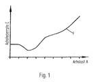
- the course of a spring identification line F is entered in FIG as the axle spring rate C depending on the axle load A on the front axle of a vehicle as is possible using the invention.
- the steady Monitoring the pressure in the piston chambers of the spring cylinder, and the Processing of the measured signals in an electrical control unit, which continuously regulates the pressure control valve enables suspension behavior without sudden changes in the spring identification line F. This makes everyone Any course of the spring identification line F is possible.
- the spring cylinders 1 and 2 are not between the unsprung and sprung masses shown. she have the piston spaces 3 and 4 by the pistons 5 and 6 of the Annuli 7 and 8 are separated.
- the piston rods 9 and 10 are sealed to the outside.
- the two annular spaces 7 and 8 are through Connection line 11 connected to each other and to the hydraulic accumulator 12 connected.
- the piston spaces 3 and 4 are via the connecting line 13 connected to one another via the line 14 with the hydraulic accumulator 15 communicated.
- the 3/2-way valve 61 connects to line 14 incoming supply line 16.
- In the feed line 16 is the throttle 63 and that unlockable check valve 17 inserted. Between the throttle 63 and the Check valve 17 connects control line 70 to supply line 16.
- the one coming from the 3/2-way valve 62 opens into the connecting line 11 Supply line 19, which also has an unlockable check valve 21 and the throttle 64 is equipped. Between the directional valve 62 and the throttle 64, the proportionally regulated pressure control valve 65 is used.
- the Control line 66 of the pressure control valve 65 is at the regulated pressure range the feed line 19 connected.
- the pressure control valve 65 has the electrical Servomotor 67, which receives the control signals from the electrical control unit 18.
- the pressure sensor 68 engages the pressure in the cylinder chambers 3 and 4 Connection line 13 from. About the electrical lines 69 are Signals from sensor 68 are transmitted to control unit 18 and there processed electronically and then passed on to the servomotor 67.
- the Control line 70 leads to the shuttle valve 71 and from there into the Control line 72 to the load-sensing pump.
- the second control line 73 of the Shuttle valve 71 is on the feed line 19 after the pressure control valve 65 connected.
- the control line 24 for unlocking the check valves 17 and 21 is on the feed line 19 between the level control valve 62 and the Pressure control valve 65 connected.
- the control unit 18 has the task of springing the vehicle smoothing alternating electrical signals from the pressure sensor so that Pressure control valve 65 a reassured control signal can be transmitted.
- the control unit 18 is advantageously designed so that it is additionally Control signals depending on work functions can link what with the control lines above the control unit was indicated.
- the pressure sensor 68 is connected directly to the control line 20 Connection line 13 of the piston chambers 3 and 4 connected so that the Pressure values can be tapped in an unadulterated manner.
- the circuit is also with the pressure relief valve 31 and Service valves 29 and 30 equipped.
Abstract
Description
Für den Fahrkomfort von Fahrzeugen mit stark wechselnden Achslasten ist eine Anpassung des Federungsverhaltens der Vorderachse an die sich verändernden Achslasten erwünscht. Abhängig vom Arbeitseinsatz kann die Vorderachse eines solchen Fahrzeugs sehr niedrigen und sehr hohen statischen Belastungen ausgesetzt sein. Bei den hydropneumatischen Federungseinrichtungen werden Niveauregler eingesetzt, die durch entsprechendes Öffnen und Schließen von Wegeventilen einen Niveauausgleich der gefederten Massen zu den ungefederten Massen bewirken. Durch entsprechendes Auf- beziehungsweise Abregeln werden bei den eingesetzten doppeltwirkenden Hydraulikzylindern der Federungseinrichtung deren Kolben auf einem mittleren Niveau gehalten.For the driving comfort of vehicles with strongly changing axle loads an adaptation of the suspension behavior of the front axle to itself changing axle loads desired. Depending on the work, the The front axle of such a vehicle is very low and very high exposed to static loads. With the hydropneumatic Suspension devices are used by level regulators Appropriate opening and closing of directional control valves Level compensation of the sprung masses to the unsprung masses cause. By appropriate up or down regulation the double-acting hydraulic cylinders used Suspension device whose pistons are kept at a medium level.
Durch DE 41 20 758 A1 ist eine hydropneumatische Federung für Kraftfahrzeuge mit großen Achslastenspreizungen bekannt geworden, bei der doppeltwirkende Hydraulikzylinder eingesetzt werden, deren Zylinderräume mit einem Speicher und der kolbenstangenseitigen Ringräume mit einem weiteren Druckspeicher verbunden sind. Ein Niveauregelventil regelt die Höhenlage und ein druckgesteuertes Ventil ein vorgegebenes Druckverhältnis zwischen Drücken des ersten und des zweiten Speichers in Abhängigkeit von der Belastung der hydropneumatischen Stellglieder. Dabei wird das druckgesteuerte Ventil sowohl vom Druck in der Druckleitung zu den Zylinderräumen als auch vom Druck der Druckleitung zu den Ringräumen betätigt.DE 41 20 758 A1 is a hydropneumatic suspension for Motor vehicles with large axle load spread become known at double-acting hydraulic cylinders are used, the cylinder spaces with a memory and the piston rod-side annular spaces with another Pressure accumulator are connected. A level control valve regulates the altitude and a pressure controlled valve a predetermined pressure ratio between Pressing the first and the second memory depending on the Load on the hydropneumatic actuators. It will pressure controlled valve both from pressure in the pressure line to the Cylinder spaces as well as from the pressure of the pressure line to the annular spaces actuated.
Eine andere Möglichkeit der Druckregelung ist in der DE 42 42 448 C1 enthalten mit dem Vorteil, dass dort Load-Sensing-Pumpen eingesetzt werden können. Dabei kommt ein Druckregelventil zum Einsatz, welches das Druckniveau im Ringraumfederkreis konstant hält. Der jeweiligen Schlepperbelastung wird das entsprechende Druckniveau zugeordnet.Another possibility of pressure control is in DE 42 42 448 C1 included with the advantage that load-sensing pumps are used there can. A pressure control valve is used, which the Pressure level in the annular space spring circuit remains constant. The respective Tractor load is assigned the corresponding pressure level.
Eine besonders gute Lösung hinsichtlich des Fahrkomforts wird bei einer Einrichtung nach der DE 197 19 077 A1 dadurch erreicht, dass als Druckregelventil ein lastangepasstes Zwei-Stufen-Druckregelventil verwendet wird. Hierdurch ist es möglich, auch größere Lastverhältnisse auszuregeln und die Federung den Belastungsfällen anzupassen. Eine Änderung des Ringraumdrucks zwischen dem unteren und dem oberen Grenzwert ist lastabhängig möglich.A particularly good solution with regard to driving comfort is one Device according to DE 197 19 077 A1 achieved that as Pressure control valve uses a load-adjusted two-stage pressure control valve becomes. This makes it possible to regulate even larger load conditions and adapt the suspension to the load cases. A change in Annulus pressure between the lower and the upper limit possible depending on the load.
Die Einrichtung nach DE 197 19 076 A1 unterscheidet sich von derjenigen aus der DE 197 19 077 A1 durch den Einsatz eines elektrischen Höhenreglers, dessen elektronisch verarbeiteten Steuersignale Magnetventile ansteuern.The device according to DE 197 19 076 A1 differs from that DE 197 19 077 A1 through the use of an electrical height regulator, control its electronically processed control signals solenoid valves.
Die Erfahrung zeigt, dass bei Federungsanlagen in Schleppern allgemein die Komfortabstimmung mittels eines 2-Stufen-Druckregelventils ausreicht. Wird jedoch eine sensiblere Abstimmung unter Berücksichtigung weiterer Abhängigkeiten gewünscht, so ist ein mehrstufiges Druckregelventil gefordert, welches sich nach dem bekannten Funktionsprinzip nur sehr aufwendig darstellen lässt.Experience shows that in suspension systems in tractors in general Comfort adjustment using a 2-stage pressure control valve is sufficient. Becomes however, a more sensitive coordination taking into account further ones Dependencies, a multi-stage pressure control valve is required, which is only very complex according to the known functional principle can be represented.
Der Erfindung liegt die Aufgabe zugrunde eine Steuerung zu schaffen, die es ermöglicht, Komfort und Fahrverhalten des Schleppers optimal an die jeweiligen Einsatzbedingungen anpassen zu können. Das Federungsverhalten soll keine sprunghaften Änderungen aufweisen. Der Fahrer soll bei allen denkbaren Fahrvorgängen eine ausreichend weiche Federung mit möglichst gleichbleibenden Amplituden verspüren.The invention has for its object to provide a control that it allows comfort and driving behavior of the tractor optimally to the to be able to adapt to the respective operating conditions The suspension behavior should not show any sudden changes. The driver should be with everyone conceivable driving a sufficiently soft suspension with as possible feel constant amplitudes.
Die Lösung der gestellten Aufgabe wird bei einer hydropneumatischen Federung für Fahrzeuge mit stark wechselnden Achslasten, insbesondere an Schleppern mit hydraulischen Federzylindern, die über Zuleitungen mit einer Druckmittelförderpumpe verbindbar sind, wobei ein Druckregelventil in die Zuleitung zu den Ringräumen der Federzylinder eingesetzt ist, erfindungsgemäß dadurch erreicht, dass das Druckregelventil ein proportional geregeltes Ventil ist, das von einem Steuerstrom aus einem elektrischen Steuergerät gesteuert wird, das die gemessenen Signale eines Drucksensors, der mit den Kolbenräumen der Federzylinder verbunden ist, elektronisch verarbeitet oder mit weiteren Funktionsdaten oder mit externen Steuersignalen aus der Arbeitshydraulik verknüpft ist.The solution to the problem is a hydropneumatic Suspension for vehicles with strongly changing axle loads, especially on Tractors with hydraulic spring cylinders, which have supply lines with a Pressure medium feed pump can be connected, with a pressure control valve in the Supply to the annular spaces of the spring cylinders is used, achieved according to the invention in that the pressure control valve is proportional regulated valve is that of a control current from an electrical Control unit that controls the measured signals of a pressure sensor, which is connected to the piston chambers of the spring cylinders, electronically processed or with further function data or with external control signals is linked from the working hydraulics.
Eine solche Lösung bietet neben der guten Anpassbarkeit der Federrate den Vorteil, bisher übliche Steuerelemente und Verbindungsleitungen für die Funktion des Druckregelventils nicht mehr zu benötigen. Der ganz besondere Vorteil liegt aber darin, dass die Achsfederrate an die gefederte Achslast kontinuierlich ohne Unterbrechung angepasst wird und auf diese Weise jeder beliebige Kurvenverlauf der Achsfederrate in Abhängigkeit von Achslast und sonstigen Betriebzuständen gewählt werden kann. Durch die vom Stellmotor vorgenommene Verstellung des Druckregelventils wird dessen Regelfeder ständig an den in der Zuleitung zu den Kolbenräumen der Federzylinder herrschenden Druck angepasst, wodurch eine ständige Druckregelung in den Ringräumen der Federzylinder erfolgt.Such a solution offers not only the good adaptability of the spring rate Advantage, previously common controls and connecting lines for the Function of the pressure control valve no longer required. The very special one The advantage, however, is that the axle spring rate depends on the spring-loaded axle load is continuously adjusted without interruption and in this way everyone any curve of the axle spring rate depending on the axle load and other operating conditions can be selected. By the from the servomotor adjustment of the pressure control valve becomes its control spring constantly on the in the supply line to the piston chambers of the spring cylinder prevailing pressure adjusted, which ensures constant pressure control in the Annealing of the spring cylinders takes place.
Anhand eines in der Zeichnung dargestellten Ausführungsbeispiels wird die Erfindung nachstehend näher erläutert.Using an embodiment shown in the drawing Invention explained in more detail below.
Es zeigt:
- Fig. 1
- den Verlauf einer Federungskennlinie, in dem die Achsfederrate in Abhängigkeit von der Achslast aufgetragen ist und
- Fig. 2
- einen Schaltplan für die hydropneumatische Federung mit einem Druckregelventil mit einem elektromagnetischen Stellmotor.
- Fig. 1
- the course of a suspension characteristic curve, in which the axle spring rate is plotted as a function of the axle load, and
- Fig. 2
- a circuit diagram for the hydropneumatic suspension with a pressure control valve with an electromagnetic actuator.
In der Fig. 1 ist der Verlauf einer Federkennungslinie F eingetragen und zwar als Achsfederrate C in Abhängigkeit von der Achslast A an der Vorderachse eines Fahrzeugs wie sie bei Anwendung der Erfindung möglich ist. Die stetige Überwachung des Drucks in den Kolbenräumen der Federzylinder, und die Verarbeitung der gemessenen Signale in einem elektrischen Steuergerät, welches das Druckregelventil stetig regelt, ermöglicht ein Federungsverhalten ohne sprunghafte Änderungen in der Federkennungslinie F. Dadurch ist jeder beliebige Verlauf der Federkennungslinie F möglich.The course of a spring identification line F is entered in FIG as the axle spring rate C depending on the axle load A on the front axle of a vehicle as is possible using the invention. The steady Monitoring the pressure in the piston chambers of the spring cylinder, and the Processing of the measured signals in an electrical control unit, which continuously regulates the pressure control valve enables suspension behavior without sudden changes in the spring identification line F. This makes everyone Any course of the spring identification line F is possible.
In der Fig. 2 ist der Schaltplan für die Vorderachsfederung eines
Schlepperfahrzeugs gezeigt. Die Federzylinder 1 und 2 sind zwischen den nicht
näher dargestellten ungefederten und gefederten Massen angeordnet. Sie
besitzen die Kolbenräume 3 und 4, die durch die Kolben 5 und 6 von den
Ringräumen 7 und 8 getrennt sind. Die Kolbenstangen 9 und 10 sind
abgedichtet nach außen geführt. Die beiden Ringräume 7 und 8 sind durch die
Verbindungsleitung 11 miteinander verbunden und an den Hydrospeicher 12
angeschlossen. Die Kolbenräume 3 und 4 sind über die Verbindungsleitung 13
miteinander verbunden, die über die Leitung 14 mit dem Hydrospeicher 15
kommuniziert. An die Leitung 14 schließt die vom 3/2-Wegeventil 61
kommende Zuleitung 16 an. In die Zuleitung 16 ist die Drossel 63 und das
entsperrbare Rückschlagventil 17 eingefügt. Zwischen der Drossel 63 und dem
Rückschlagventil 17 schließt die Steuerleitung 70 an die Zuleitung 16 an.2 is the circuit diagram for the front axle suspension one
Tractor vehicle shown. The spring cylinders 1 and 2 are not between the
unsprung and sprung masses shown. she
have the
In die Verbindungsleitung 11 mündet die vom 3/2-Wegeventil 62 kommende
Zuleitung 19, die ebenfalls mit einem entsperrbaren Rückschlagventil 21 und
der Drossel 64 ausgestattet ist. Zwischen dem Wegeventil 62 und der Drossel
64 ist das proportional geregelte Druckregelventil 65 eingesetzt. Die
Steuerleitung 66 des Druckregelventils 65 ist an dem geregelten Druckbereich
der Zuleitung 19 angeschlossen. Das Druckregelventil 65 hat den elektrischen
Stellmotor 67, der die Steuersignale vom elektrischen Steuergerät 18 erhält.
Der Drucksensor 68 greift den Druck in den Zylinderräumen 3 und 4 an der
Verbindungsleitung 13 ab. Über die elektrischen Leitungen 69 werden die
Signale des Sensors 68 an das Steuergerät 18 übertragen und dort
elektronisch verarbeitet und dann weiter an den Stellmotor 67 geleitet. Die
Steuerleitung 70 führt zu dem Wechselventil 71 und von dort in die
Steuerleitung 72 zur Load-Sensing-Pumpe. Die zweite Steuerleitung 73 des
Wechselventils 71 ist an die Zuleitung 19 nach dem Druckregelventil 65
angeschlossen. Die Steuerleitung 24 für die Entsperrung der Rückschlagventile
17 und 21 ist an der Zuleitung 19 zwischen dem Niveauregelventil 62 und dem
Druckregelventil 65 angeschlossen.The one coming from the 3/2-
Das Steuergerät 18 hat die Aufgabe, die beim Federn des Fahrzeugs
wechselnden elektrischen Signale des Drucksensors zu glätten, damit dem
Druckregelventil 65 ein beruhigtes Steuersignal übermittelt werden kann. In
vorteilhafter Weise ist das Steuergerät 18 so konzipiert, dass es zusätzlich
Steuersignale in Abhängigkeit von Arbeitsfunktionen verknüpfen kann, was mit
den Steuerleitungen oberhalb des Steuergeräts angedeutet wurde.The
Der Drucksensor 68 ist über die Steuerleitung 20 unmittelbar an die
Verbindungsleitung 13 der Kolbenräume 3 und 4 angeschlossen, damit die
Druckwerte unverfälscht abgreifbar sind.The
Die Schaltung ist außerdem noch mit dem Überdruckventil 31 und den
Serviceventilen 29 und 30 ausgestattet.The circuit is also with the
Claims (3)
Applications Claiming Priority (2)
| Application Number | Priority Date | Filing Date | Title |
|---|---|---|---|
| DE10107644A DE10107644B4 (en) | 2001-02-15 | 2001-02-15 | Hydropneumatic suspension for vehicles with heavily varying axle loads |
| DE10107644 | 2001-02-15 |
Publications (2)
| Publication Number | Publication Date |
|---|---|
| EP1232882A2 true EP1232882A2 (en) | 2002-08-21 |
| EP1232882A3 EP1232882A3 (en) | 2004-11-24 |
Family
ID=7674518
Family Applications (1)
| Application Number | Title | Priority Date | Filing Date |
|---|---|---|---|
| EP02000848A Withdrawn EP1232882A3 (en) | 2001-02-15 | 2002-01-15 | Hydropneumatic suspension for vehicles with highly varying axle loads |
Country Status (3)
| Country | Link |
|---|---|
| US (1) | US6644096B2 (en) |
| EP (1) | EP1232882A3 (en) |
| DE (1) | DE10107644B4 (en) |
Cited By (2)
| Publication number | Priority date | Publication date | Assignee | Title |
|---|---|---|---|---|
| WO2007073786A3 (en) * | 2005-12-24 | 2007-10-11 | Hydac System Gmbh | Hydropneumatic axle suspension for vehicles |
| ITUB20160745A1 (en) * | 2016-02-15 | 2017-08-15 | Cnh Ind Italia Spa | A PROCESS OF CONTROL FOR THE SUSPENSIONS OF A VEHICLE |
Families Citing this family (8)
| Publication number | Priority date | Publication date | Assignee | Title |
|---|---|---|---|---|
| DE10232769B4 (en) | 2002-07-18 | 2005-08-25 | Carl Freudenberg Kg | Hydro-pneumatic axle suspension for vehicles with heavily changing axle loads |
| JP4492123B2 (en) * | 2004-01-05 | 2010-06-30 | 旭硝子株式会社 | Silica glass |
| DE102004040636A1 (en) * | 2004-08-21 | 2006-02-23 | Hydac System Gmbh | suspension device |
| DE102012106185B3 (en) | 2012-07-10 | 2013-11-21 | Fsp Fluid Systems Partners Holding Ag | Control arrangement for a hydropneumatic suspension system and hydropneumatic suspension system with such a control arrangement |
| DE102013102069A1 (en) | 2013-03-01 | 2014-09-04 | Fsp Fluid Systems Partners Holding Ag | Proportional directional valve and hydraulic circuit and hydropneumatic suspension system with such a valve |
| DE102013222254B4 (en) * | 2013-10-31 | 2022-06-02 | Deere & Company | Harvester with suspended rear axle arrangement |
| EP2875975B1 (en) | 2013-11-22 | 2019-05-22 | Weber-Hydraulik GmbH | Hydraulic circuit and use of same |
| US11358430B2 (en) * | 2020-06-16 | 2022-06-14 | Deere & Company | Suspension system with variable roll resistance |
Citations (4)
| Publication number | Priority date | Publication date | Assignee | Title |
|---|---|---|---|---|
| DE4120758A1 (en) | 1990-06-28 | 1992-01-02 | Zahnradfabrik Friedrichshafen | HYDROPNEUMATIC SUSPENSION FOR VEHICLES |
| DE4242448C1 (en) | 1992-12-16 | 1994-03-31 | Integral Hydraulik Co | Hydropneumatic spring mechanism for tractor - uses three-way valve combination and load sensing pump. |
| DE19719077A1 (en) | 1997-05-06 | 1998-11-12 | Integral Hydraulik Gmbh & Co F | Hydropneumatic vehicle suspension |
| DE19719076A1 (en) | 1997-05-06 | 1998-11-12 | Integral Hydraulik Gmbh & Co F | Hydropneumatic vehicle suspension |
Family Cites Families (6)
| Publication number | Priority date | Publication date | Assignee | Title |
|---|---|---|---|---|
| FR92847E (en) * | 1967-03-29 | 1969-01-03 | Ind Dev Company Establishments | Hydropneumatic suspension at constant load. |
| DE2304728C3 (en) * | 1973-01-31 | 1975-07-31 | Pietzsch, Ludwig, Dr.-Ing., 7500 Karlsruhe | Suspension system for off-road vehicles |
| JPS521770B2 (en) * | 1973-07-04 | 1977-01-18 | ||
| JPS5317053Y2 (en) * | 1974-03-04 | 1978-05-08 | ||
| SU1243964A1 (en) * | 1985-01-14 | 1986-07-15 | Рижское Высшее Военно-Политическое Краснознаменное Училище Им.Бирюзова С.С. | Active air-oil suspension of vehicle |
| US5137299A (en) * | 1991-04-26 | 1992-08-11 | Trw Inc. | Active suspension system |
-
2001
- 2001-02-15 DE DE10107644A patent/DE10107644B4/en not_active Expired - Fee Related
-
2002
- 2002-01-15 EP EP02000848A patent/EP1232882A3/en not_active Withdrawn
- 2002-02-13 US US10/075,550 patent/US6644096B2/en not_active Expired - Fee Related
Patent Citations (4)
| Publication number | Priority date | Publication date | Assignee | Title |
|---|---|---|---|---|
| DE4120758A1 (en) | 1990-06-28 | 1992-01-02 | Zahnradfabrik Friedrichshafen | HYDROPNEUMATIC SUSPENSION FOR VEHICLES |
| DE4242448C1 (en) | 1992-12-16 | 1994-03-31 | Integral Hydraulik Co | Hydropneumatic spring mechanism for tractor - uses three-way valve combination and load sensing pump. |
| DE19719077A1 (en) | 1997-05-06 | 1998-11-12 | Integral Hydraulik Gmbh & Co F | Hydropneumatic vehicle suspension |
| DE19719076A1 (en) | 1997-05-06 | 1998-11-12 | Integral Hydraulik Gmbh & Co F | Hydropneumatic vehicle suspension |
Cited By (3)
| Publication number | Priority date | Publication date | Assignee | Title |
|---|---|---|---|---|
| WO2007073786A3 (en) * | 2005-12-24 | 2007-10-11 | Hydac System Gmbh | Hydropneumatic axle suspension for vehicles |
| US8096568B2 (en) | 2005-12-24 | 2012-01-17 | Hydac System Gmbh | Hydropneumatic axle suspension for vehicles |
| ITUB20160745A1 (en) * | 2016-02-15 | 2017-08-15 | Cnh Ind Italia Spa | A PROCESS OF CONTROL FOR THE SUSPENSIONS OF A VEHICLE |
Also Published As
| Publication number | Publication date |
|---|---|
| US6644096B2 (en) | 2003-11-11 |
| EP1232882A3 (en) | 2004-11-24 |
| DE10107644A1 (en) | 2002-09-05 |
| DE10107644B4 (en) | 2005-02-10 |
| US20020157451A1 (en) | 2002-10-31 |
Similar Documents
| Publication | Publication Date | Title |
|---|---|---|
| EP1963118B1 (en) | Hydropneumatic axle suspension for vehicles | |
| EP1778508A1 (en) | Suspension system | |
| EP1232883B1 (en) | Hydropneumatic vehicle suspension system | |
| EP1508461A1 (en) | Hydopneumatic suspension | |
| DE10307346A1 (en) | valve assembly | |
| DE10232769B4 (en) | Hydro-pneumatic axle suspension for vehicles with heavily changing axle loads | |
| DE20208577U1 (en) | Electro-hydraulic lift control device for industrial trucks | |
| DE10111551A1 (en) | Active chassis system of a vehicle | |
| DE10107644B4 (en) | Hydropneumatic suspension for vehicles with heavily varying axle loads | |
| EP3444482B1 (en) | Device for controlling the charge state of at least one pressure accumulator | |
| EP3914463B1 (en) | Spring-damper system | |
| DE19719076C2 (en) | Hydropneumatic suspension device for vehicles with high load conditions | |
| DE102018114495A1 (en) | Load signal control of an implement's working hydraulics | |
| DE102006004423A1 (en) | Valve arrangement for controlling double action lifting gear or add-on device of agricultural utility vehicle, has direction control, and pressure suspended at pressure limiting valve is adjustable with increase of flow rate | |
| DE4308004C2 (en) | Hydraulic control device for multiple consumers | |
| DE3300662A1 (en) | Level control device for vehicles | |
| DE4035313C2 (en) | System for controlling a chassis | |
| EP2466154B1 (en) | Electrohydraulic control device | |
| DE19709958B4 (en) | Hydrostatic drive system | |
| EP2157320B1 (en) | Hydraulic device for a hydro motor | |
| EP3398418A1 (en) | Hydraulic system of a machine usable in agriculture or civil engineering | |
| DE19719075B4 (en) | Double-acting valve for influencing the current, in particular for hydro-pneumatic suspension devices for vehicles with high load ratios | |
| WO2005093263A1 (en) | Hydraulic control system | |
| DE4313250C2 (en) | Hydraulic control device | |
| DE4118822C2 (en) |
Legal Events
| Date | Code | Title | Description |
|---|---|---|---|
| PUAI | Public reference made under article 153(3) epc to a published international application that has entered the european phase |
Free format text: ORIGINAL CODE: 0009012 |
|
| AK | Designated contracting states |
Kind code of ref document: A2 Designated state(s): AT BE CH CY DE DK ES FI FR GB GR IE IT LI LU MC NL PT SE TR |
|
| AX | Request for extension of the european patent |
Free format text: AL;LT;LV;MK;RO;SI |
|
| PUAL | Search report despatched |
Free format text: ORIGINAL CODE: 0009013 |
|
| AK | Designated contracting states |
Kind code of ref document: A3 Designated state(s): AT BE CH CY DE DK ES FI FR GB GR IE IT LI LU MC NL PT SE TR |
|
| AX | Request for extension of the european patent |
Extension state: AL LT LV MK RO SI |
|
| AKX | Designation fees paid | ||
| REG | Reference to a national code |
Ref country code: DE Ref legal event code: 8566 |
|
| STAA | Information on the status of an ep patent application or granted ep patent |
Free format text: STATUS: THE APPLICATION IS DEEMED TO BE WITHDRAWN |
|
| 18D | Application deemed to be withdrawn |
Effective date: 20050802 |