EP1232441B1 - Verfahren zum datenaustausch bei einem mehrprozessorsystem - Google Patents
Verfahren zum datenaustausch bei einem mehrprozessorsystem Download PDFInfo
- Publication number
- EP1232441B1 EP1232441B1 EP00988579A EP00988579A EP1232441B1 EP 1232441 B1 EP1232441 B1 EP 1232441B1 EP 00988579 A EP00988579 A EP 00988579A EP 00988579 A EP00988579 A EP 00988579A EP 1232441 B1 EP1232441 B1 EP 1232441B1
- Authority
- EP
- European Patent Office
- Prior art keywords
- data
- subprocessor
- message
- block
- standard
- Prior art date
- Legal status (The legal status is an assumption and is not a legal conclusion. Google has not performed a legal analysis and makes no representation as to the accuracy of the status listed.)
- Expired - Lifetime
Links
Images


Classifications
-
- G—PHYSICS
- G05—CONTROLLING; REGULATING
- G05B—CONTROL OR REGULATING SYSTEMS IN GENERAL; FUNCTIONAL ELEMENTS OF SUCH SYSTEMS; MONITORING OR TESTING ARRANGEMENTS FOR SUCH SYSTEMS OR ELEMENTS
- G05B19/00—Program-control systems
- G05B19/02—Program-control systems electric
- G05B19/04—Program control other than numerical control, i.e. in sequence controllers or logic controllers
- G05B19/042—Program control other than numerical control, i.e. in sequence controllers or logic controllers using digital processors
- G05B19/0421—Multiprocessor system
Definitions
- the invention relates to a method for data exchange a multiprocessor system that has an upper processor and at least has a subprocessor, which is via a system bus communicate with each other, using the multiprocessor system via an interface to the main processor for data exchange with an external system.
- the subprocessor carries out control tasks on a system.
- Such a multi-processor system is often used in motor vehicles used to perform various control tasks with one to accomplish as a multi-processor control unit.
- the multiprocessor system has predefined application data, which are accessed during operation, and Operating data that are processed within the system and each according to the operating state of the controlled system, for example of the vehicle.
- Application When designing such a multiprocessor system you have to Select the data record with application data appropriately. this will referred to as "application”. The later are constant Application data in the memory of the multiprocessor system changed and the reactions observed to optimize to be able to perform.
- An example application date for a The multi-processor system controlling the internal combustion engine is the one at ignition angle to be selected at a specific load point.
- Multi-processor systems now have the disadvantage in application that the user must manage the individual processors.
- a communication network is known from EP 0 562 333 A2, where a central control node and distributed control nodes communicate with each other.
- the network is with a serial Bus designed and speaks the distributed control nodes periodically after a predetermined number of time cycles.
- Each control node is assigned one to determine the sequence Ordinal number assigned.
- a standard message within the system Communication is provided that is downward, i.e. from the main processor to the subprocessor, or upward, i.e. from the subprocessor to the main processor. Any standard message is sent over the system bus and exists from several data blocks. Downward standard messages exist at least one of the addressed subprocessors identifying address block, a counter block containing the number of a subsequent application data block, at least one operating data block that is relevant for the current Operation of the subprocessor contains relevant operating data and at least one application data block.
- This application data block can during the application of the system, i.e. while the user is designing an external one Application system the later constant application data specifies different application data for each downward transmission contain.
- a query command is transmitted to the multiprocessor system instructs the current value of a specific operating date to transmit.
- the multiprocessor system sets that Query command in the next standard downward message the addressed subprocessor, which then updates the current one Value transmitted to the main processor, from where it to the Application system is sent.
- upward standard messages used in a return communication can be sent to the standard downward messages and are also made up of several data blocks.
- a Standard upward message consists of at least one operational data block and a display data block that matches the Query command contains queried date.
- the subprocessors have no non-volatile memory.
- initialization messages which are also like standard messages from data blocks are built, among other things, the message identification block characterizing the initialization message and comprise at least one application data block, which is the one required for further operation Application data at least partially contains. Is the number the application data so large that it does not have an initialization message can be transferred, also several Initialization messages are provided on the the necessary application data are distributed. At this The standard messages are also advantageous upstream of an identification block, which they use as standard messages features.
- the invention finds a particularly advantageous use when controlling an electromechanically actuated valve train by means of a multiprocessor system. It is about an example of a multi-processor system in vehicle use with small amounts of data to be transferred.
- a multi-processor system in vehicle use with small amounts of data to be transferred.
- This Multiprocessor system there is an internal bus connection, for example through an SPI bus between the main processor, which is a communication computer, and the subprocessors, which, for example, from touchdown regulators, the individual electromechanically address actuated gas exchange valves.
- the communication computer is usually from the outside via a CAN bus addressed. This bus is used during the application the connection between the application system and the Gateway.
- the advantage of the method according to the invention is then, among other things, that not every landing computer requires a connection to the CAN bus, and that the application by simply addressing the communication computer can be done via the CAN bus.
- the default is existing communication between the computers of the Multi-processor system by the inventive method in their functionality expanded so that a simplified application is possible.
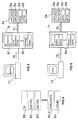
- a multiprocessor system is shown schematically in FIG. It consists of an upper processor 1a and several Among processors. In this example there are three Subprocessors 2a, 2b and 2c. Processor 1a and subprocessors 2a, 2b and 2c are via an internal bus 11 connected to each other. The entire multiprocessor system 10 is via an external connection 12 to an application system 13 connectable.
- the upper processor 1a communicates with the subprocessors 2a, 2b, 2c via the intrinsic bus 11.
- the subprocessors 2a, 2b, 2c for example, perform a control task on a Plant through. You need application data for this control task. This is fixed data, which, for example, the response of the subprocessor play a certain operating state. Further edited each subprocessor 2a, 2b, 2c so-called operating data, that change during operation of the multiprocessor system 10 can. With such an operating date it can be act, for example, as a measured variable of a controlled system.
- Each subprocessor 2a, 2b, 2c has memory cells Sa and Sd, in which the application data and the operating data are filed. For simplicity, only one is shown in FIG. 1 Memory cell Sa and a memory cell Sd and this only shown for the subprocessor 2a. Realiter is natural a large number of memory cells are present in each subprocessor.
- FIG. 7 An example of such a multi-processor system 10, which in the the following will be described in more detail at Control of electromagnetic gas exchange valves of an internal combustion engine.
- Such a multiprocessor system is shown in FIG. 7 shown.
- the circuit of FIG. 7 is used to control electromechanically driven gas exchange valves 5a, 5b, 6a, 6b.
- electromechanically driven gas exchange valves 5a, 5b, 6a, 6b On is such an electromechanically driven gas exchange valve for example in German utility model 297 12 502 U1 described.
- this invention is included only essential; that the electromechanically operated gas exchange valve is actuated by energizing two coils, one coil for closing, the other for opening of the gas exchange valve is responsible.
- Fig. 7 is the circuit for a four-cylinder internal combustion engine schematically shown, however, this number of cylinders to be understood only as an example.
- a cylinder has in In this example, two inlet valves 5a, 5b and two outlet valves 6a, 6b.
- For the intake and exhaust valves 5a, 5b or 6a, 6b is a respective landing regulator 2 or 3 intended.
- These touchdown controllers are subprocessors of the Multi-processor system to be described in more detail.
- the touchdown controller 2, 3 controls output stages, which energize the the respective coils of the gas exchange valve 5a, 5b, 6a, 6b. There is, for example, one for each coil own power amplifier provided.
- the placement controller 2, 3 controls the output stages of a valve 5, 6 depending on a timing signal indicating when open or close the valve. For the intake and the exhaust valves of each cylinder have their own Timing signal.
- the timing signal is sent to the touchdown controller 2, 3 via a u-directional Communication line 4 from a communication computer 1 fed.
- This is the main processor 1a of the multiprocessor system 10.
- the touchdown controller 2, 3 has a digital processor that powers the coils regulated by the output stages so that the valve 5a, 5b, 6a, 6b touches down gently in the desired end position.
- the touchdown controller 2, 3 is via a serial SPI bus Interface connected to the communication computer 1 and reports the status of the valves 5a, 5b, 6a, 6b or a possible one Valve failure via this interface. The function this interface will be explained later.
- the communication computer 1 is connected to a CAN bus 8 and uses it to communicate with the operating control unit 9 of the internal combustion engine.
- a CAN bus 8 uses it to communicate with the operating control unit 9 of the internal combustion engine.
- Such BUS connection is, for example, in W. Lawrenz, CAN controller Area Network, Hüthig Verlag, 1994, ISBN 3-7785-2263-7 described.
- the CAN bus 8 is an exemplary implementation of the external one Connection 12 between an application system 13 and the multiprocessor system 10.
- the communication computer 1 is in this embodiment, the main processor 1a, and the individual touchdown controllers 2, 3 the subprocessors.
- the intrinsic Bus 11 of this multiprocessor system 10 is an SPI bus 7 trained.
- the internal communication via the SPI bus 7 now runs as follows: With the start of the multiprocessor system 10 the communication computer 1 automatically sends initialization messages to all add-on controllers. Such an initialization message is shown schematically in Fig. 3. She consists of different blocks B0 to Bn. The block size is 8 bits, but each is also any other Block size conceivable. However, the block size should be at least have the size of the data type used, so a Individual dates do not have to be divided into two blocks.
- the first block B0 of the initialization message is an identification block BI, the initialization message as characterizes such.
- the second block B1 is a counting block which instructs where the following application data in the corresponding Memory cells Sa of the subprocessor concerned are to be discarded.
- the initialization message is completed by a block Bn, which is a test block CSUM is, by means of, for example, a checksum it can be checked whether the initialization message is correct was obtained.
- the counting block BC thus shows in for a single subprocessor successive initialization messages the memory cell Sa, on which the data subsequently transmitted are transmitted Application data APPLDATA1 to APPLDATAx must be stored. Addressing is also carried out in identification block BI of the affected subprocessor or touchdown controller.
- the subprocessors 2a, 2b, 2c, i.e. touchdown controllers 2 and 3 remain in the initialization state until they have all of their application data records received completely and correctly. Each touchdown controller 2, 3 checks whether it has all the required application data had received. If one is missing, the person is waiting Lift controller until it has this required application date gets transferred. It is only then ready for operation. How this application date can be transferred will be explained later.
- a touchdown controller recognizes from the test block that a Block or message should have arrived incorrectly becomes the communications computer in a manner to be described 1 or head processor 1a communicated that the data is not have arrived correctly and that a repeated broadcast is required is. The communication computer 1 then repeats this initialization message for this subprocessor to ensure correct transmission.
- Downward standard messages from the gateway 1 are directed to the ride-on controller 2, 3 and standard upward messages in the opposite direction.
- Such Downward standard message is shown schematically in Fig. 2. It consists of several blocks B0 to Bn, their data format preferably that of the blocks of the initialization message equivalent.
- the first block B0 is again an identification block, on the one hand the message as a standard message identifies and on the other hand the affected Lift controller addressed.
- the next block is B1 again a counter block BC, to which the touchdown controller is addressed can see at which memory cell Sa a later in the Classify application date transmitted downward standard message is.
- This downward standard message enables application data to inform the affected touchdown controller. This can be done in two cases may be necessary: First, the communication computer shares 1 touchdown controller 2, 3 still missing Application data with, if this despite repeated initialization messages about a still to be described The standard upward message signaled that he was not all Application data received. On the other hand, during the application the user gives the communication computer 1 new application data pretend. The communication computer 1 determines then the affected controller and shares it with them relevant new application data in several downward standard messages With.
- the standard upward message starts again with a first Block B0, which is in the identification block BI.
- This identifies the message as an upward standard message and contains, for example, a status message from the respective subprocessor.
- This is followed by a series of blocks B2, B3, ... on, the operating data DATA1, DATA2 of the touchdown controller contain.
- the other described the existing counter block BC itself in the standard upward messages.
- To the operating data is followed by a block Bn-1, which contains the current value ONLDATA indicates an operating date.
- a CSUM test block completes the upward standard message in block Bn.
- Block Bn-1 with the current value ONLDATA becomes an application of the multiprocessor system used as follows.
- the multiprocessor system 10 is for application via an external Connection 12, in this case the CAN-8 with an application system 13 connected.
- the application system 13 On the application system 13, as mentioned, the user enters and reads out data.
- the The user proceeds by doing a certain sentence Prescribes application data, and then the behavior of the multiprocessor system 10 or one of them regulated internal combustion engine supervised. To do this, he would like to display certain operating data to have.
- the procedure shown in FIG. 5 shown schema a query command for a date DATAn discontinued. This is in the direction of arrow 16 Transfer CAN bus 8 to communication computer 1.
- the communication computer 1 thereupon as the main processor 1a determines in which of the touchdown controller or subprocessors this Date available, or in which memory cell Sd it is is located there.
- the communication computer 1 sets a query command SHOW @ n in the next standard downward message to the affected subprocessor 2a in the block Bn-1 a.
- This message is sent in the direction of arrow 17 transmit the SPI bus 7 to the subprocessor 2a.
- subprocessor 2a transmits in the following Standard upward message in the direction of arrow 18 the content of the queried memory cell via the SPI bus 7 as current value ONLDATA. In this case it is about the content DATAn.
- the communication computer 1 takes out as the main processor 1a after receiving this standard upward message this content to block Bn-1 and sends it via the CAN bus 8 in the direction of arrow 19 to the application system 13 where it is displayed.
Landscapes
- Physics & Mathematics (AREA)
- General Physics & Mathematics (AREA)
- Engineering & Computer Science (AREA)
- Automation & Control Theory (AREA)
- Multi Processors (AREA)
Description
Claims (6)
- Verfahren zum Datenaustausch bei einem Mehrprozessorsystem, das einen Oberprozessor und mindestens einen eine Regelaufgabe an einer Anlage durchführenden Unterprozessor aufweist, wobei Ober- und Unterprozessor über einen Systembus miteinander kommunizieren, und am Oberprozessor eine Schnittstelle zum Datenaustausch mit einem externen System vorgesehen ist, bei welchem Verfahrena) wiederkehrende Abwärts-Standardbotschaften vom Oberprozessor zum Unterprozessor über den Systembus geschickt werden,b) auf jede Abwärts-Standardbotschaft der Unterprozessor mit einer Aufwärts-Standardbotschaft vom Unterprozessor zum Oberprozessor antwortet,die Abwärts-Standardbotschaften mehrere Datenblöcke mit mindestensa1) einem den adressierten Unterprozessor kennzeichenden Adreßblock,a2) einem Zählerblock, der die Nummer eines in der Abwärts-Standardbotschaft folgenden Applikationsdatenblockes bezeichnet,a3) mindestens einem Betriebsdatenblock, der für den aktuellen Betrieb des Unterprozessors vorgegebene Betriebsdaten enthält, unda4) mindestens einem Applikationsdatenblock, der für den gesamten Betrieb des Unterprozessors relevante Applikationsdaten enthält, wobei als Applikationsdatum auch ein Abfragebefehl für ein aktuell im Unterprozessor vorhandenes Datum gegeben werden kann, unddie Aufwärts-Standardbotschaften mehrere Datenblöcke mitaufzuweisen,b1) mindestens einem Betriebsdatenblock, der im aktuellen Betrieb des Unterprozessors verwendete Betriebsdaten enthält, undb2) einem Anzeigedatenblock, der das zuletzt mit einem Abfragebefehl abgefragte Datum enthält,wobei der Unterprozessor ein zuletzt mit einer Abwärts-Standardbotschaft abgefragtes Datum so lange wiederholt im Anzeigedatenblock seiner Aufwärts-Standardbotschaft übermittelt, bis ein neues Datum abgefragt wird.
- Verfahren nach Anspruch 1,
dadurch gekennzeichnet, daß vor Schritt a) mit Inbetriebnahme mindestens eine Initialisierungsbotschaft vom Oberprozessor zu jedem Unterprozessor geschickt wird, die aus mehreren Datenblöcken mit mindestens einem Applikationsdatenblock, der für den folgenden Betrieb der Unterprozessoren relevante Applikationsdaten enthält, besteht, und daß jeder Botschaft ein sie als Initialisierungs- oder Standardbotschaft kennzeichnender Identifikationsblock vorangestellt wird, der vorzugsweise auch den Adreßblock beinhaltet. - Verfahren nach Anspruch 1 oder 2,
dadurch gekennzeichnet, daß bei einem eine Anlage, insbesondere eine Brennkraftmaschine steuernden Mehrprozessorsystem zuerst ein erster Applikationsdatensatz vorgegeben wird, während der Anlagensteuerung über Abwärts-Standardbotschaften Applikationsdaten dieses Datensatzes verändert werden und mittels geeigneter Abfragebefehle in Abwärts-Standardbotschaften die Abfrage von aktuellen Daten bewirkt und deren Anzeige veranlaßt wird, um den Applikationsdatensatz zu optimieren. - Verfahren nach einem der vorherigen Ansprüche,
dadurch gekennzeichnet, daß der Abfragebefehl eine Speicheradresse im Unterprozessor angibt, an der das abgefragte Datum liegt. - Verfahren nach Anspruch 2,
dadurch gekennzeichnet, daß der Unterprozessor während der Inbetriebnahme überprüft, ob er mit der mindestens einen Initialisierungsbotschaft alle Applikationsdaten erhalten hat und erst dann mit einer Aufwärts-Standardbotschaft antwortet. - Verfahren nach einem der vorherigen Ansprüche,
dadurch gekennzeichnet, daß sich an jede Botschaft ein Prüfblock anschließt, der eine Überprüfung der Botschaft auf Übertragungsfehler ermöglicht, und daß der Unterprozessor beim Empfang einer fehlerhaften Botschaft diese verwirft und mit den bislang vorliegenden Applikationsdaten weiterarbeitet, bis er wieder eine gültige Botschaft mit neuen Applikationsdaten empfängt.
Applications Claiming Priority (3)
| Application Number | Priority Date | Filing Date | Title |
|---|---|---|---|
| DE19955092A DE19955092C2 (de) | 1999-11-16 | 1999-11-16 | Verfahren zum Datenaustausch bei einem Mehrprozessorsystem |
| DE19955092 | 1999-11-16 | ||
| PCT/DE2000/003939 WO2001037100A2 (de) | 1999-11-16 | 2000-11-10 | Verfahren zum datenaustausch bei einem mehrprozessorsystem |
Publications (2)
| Publication Number | Publication Date |
|---|---|
| EP1232441A2 EP1232441A2 (de) | 2002-08-21 |
| EP1232441B1 true EP1232441B1 (de) | 2003-06-04 |
Family
ID=7929217
Family Applications (1)
| Application Number | Title | Priority Date | Filing Date |
|---|---|---|---|
| EP00988579A Expired - Lifetime EP1232441B1 (de) | 1999-11-16 | 2000-11-10 | Verfahren zum datenaustausch bei einem mehrprozessorsystem |
Country Status (4)
| Country | Link |
|---|---|
| US (1) | US6948167B1 (de) |
| EP (1) | EP1232441B1 (de) |
| DE (2) | DE19955092C2 (de) |
| WO (1) | WO2001037100A2 (de) |
Families Citing this family (2)
| Publication number | Priority date | Publication date | Assignee | Title |
|---|---|---|---|---|
| US7594226B2 (en) * | 2004-08-16 | 2009-09-22 | National Instruments Corporation | Implementation of packet-based communications in a reconfigurable hardware element |
| US8255901B2 (en) * | 2005-12-16 | 2012-08-28 | Sap Ag | Methods and systems for configuring software applications |
Family Cites Families (13)
| Publication number | Priority date | Publication date | Assignee | Title |
|---|---|---|---|---|
| DE3538214C2 (de) * | 1984-10-30 | 1994-06-16 | Mitsubishi Electric Corp | Multiprozessorsystem |
| US4805137A (en) * | 1987-01-08 | 1989-02-14 | United Technologies Corporation | Bus controller command block processing system |
| US4805187A (en) * | 1987-10-15 | 1989-02-14 | General Electric Company | Determination of substrate temperature used during oxygen implantation of SIMOX wafer |
| US5390351A (en) * | 1992-03-06 | 1995-02-14 | Pitney Bowes Inc. | System for communicating with plural nodes in predetermined intervals depended on integers assigned and changed based upon configuration thereof |
| US5835911A (en) * | 1994-02-08 | 1998-11-10 | Fujitsu Limited | Software distribution and maintenance system and method |
| DE4408488A1 (de) * | 1994-03-14 | 1995-09-21 | Bosch Gmbh Robert | Verfahren zur zyklischen Übertragung von Daten zwischen mindestens zwei verteilt arbeitenden Steuergeräten |
| JP2771951B2 (ja) * | 1994-11-10 | 1998-07-02 | インターナショナル・ビジネス・マシーンズ・コーポレイション | リアクティブ・システムのためのプログラム作成装置 |
| US6151620A (en) * | 1997-10-22 | 2000-11-21 | Novell, Inc. | Conference messaging system |
| US6324692B1 (en) * | 1999-07-28 | 2001-11-27 | Data General Corporation | Upgrade of a program |
| US6715145B1 (en) * | 1999-08-31 | 2004-03-30 | Accenture Llp | Processing pipeline in a base services pattern environment |
| US6854009B1 (en) * | 1999-12-22 | 2005-02-08 | Tacit Networks, Inc. | Networked computer system |
| US6754738B2 (en) * | 2001-09-28 | 2004-06-22 | International Business Machines Corporation | Low overhead I/O interrupt |
| US6748460B2 (en) * | 2001-09-28 | 2004-06-08 | International Business Machines Corporation | Initiative passing in an I/O operation without the overhead of an interrupt |
-
1999
- 1999-11-16 DE DE19955092A patent/DE19955092C2/de not_active Expired - Fee Related
-
2000
- 2000-11-10 US US10/130,452 patent/US6948167B1/en not_active Expired - Fee Related
- 2000-11-10 DE DE50002495T patent/DE50002495D1/de not_active Expired - Fee Related
- 2000-11-10 WO PCT/DE2000/003939 patent/WO2001037100A2/de not_active Ceased
- 2000-11-10 EP EP00988579A patent/EP1232441B1/de not_active Expired - Lifetime
Also Published As
| Publication number | Publication date |
|---|---|
| WO2001037100A2 (de) | 2001-05-25 |
| EP1232441A2 (de) | 2002-08-21 |
| DE19955092A1 (de) | 2001-05-23 |
| WO2001037100A3 (de) | 2001-12-13 |
| US6948167B1 (en) | 2005-09-20 |
| DE19955092C2 (de) | 2002-11-28 |
| DE50002495D1 (de) | 2003-07-10 |
Similar Documents
| Publication | Publication Date | Title |
|---|---|---|
| EP0577919B1 (de) | Zugriffssteuerung für gekoppelte maskenprogrammierte Mikrocontroller | |
| DE69809254T2 (de) | Architektur eines hybriden echzeitsteuerungssystems und verfahren zu seinem betrieb | |
| DE60200210T2 (de) | Über das World-Wide-Web zugängliche, eingebettete Programmier-Software | |
| DE69921446T2 (de) | Übertragungsstruktur für industrielle prozesssteuerungssysteme | |
| WO1992017962A1 (de) | Verfahren zum aufbau von botschaften für den datenaustausch und/oder für die synchronisation von prozessen in datenverarbeitungsanlagen | |
| EP0951682A1 (de) | IO- UND SPEICHERBUSSYSTEM FÜR DFPs SOWIE BAUSTEINE MIT ZWEI- ODER MEHRDIMENSIONALEN PROGRAMMIERBAREN ZELLSTRUKTUREN | |
| EP0524344A1 (de) | Konfigurierbare Werkzeugmaschinensteuerung | |
| EP2825921B1 (de) | Steuerungsvorrichtung zum steuern von sicherheitskritischen prozessen in einer automatisierten anlage und verfahren zur parameterierung der steuerungsvorrichtung | |
| DE10317390A1 (de) | Datenübertragungseinrichtung und elektronische Steuereinheit | |
| DE10254010A1 (de) | Verfahren und Datennetzwerk zur automatischen Konfiguration einer Parametrieroberfläche von Werkzeugmaschinen oder Produktionsmaschinen | |
| DE69122142T2 (de) | Steuerungsanlage für ein Mehrprozessorsystem | |
| EP3019920B1 (de) | Datenerfassungseinheit und automatisierungssystem | |
| EP2957075B1 (de) | Master-busgerät für einen fahrzeugkommunikationsbus eines kraftwagens | |
| EP4170443A1 (de) | Steuerungseinrichtung und verfahren zum umschalten von ein-/ausgabeeinheiten einer steuerungseinrichtung | |
| DE60012241T2 (de) | Fahrzeugsteuerungseinrichtung und Methode zur Verteilung der Steuerungsdaten | |
| DE19860069B4 (de) | Programmierbare Steuereinrichtung | |
| EP0360135B1 (de) | Verfahren zur Interruptverarbeitung in einer Datentverarbeitungsanlage | |
| EP0509114B1 (de) | Verfahren zum Übertragen von Daten an mehrere Datenstationen | |
| EP4309033B1 (de) | Computerimplementiertes verfahren und vorrichtung zur automatisierten aktualisierung einer kommunikationseinheit einer steuereinheit eines fahrzeugs | |
| DE3938517C2 (de) | ||
| DE19955092C2 (de) | Verfahren zum Datenaustausch bei einem Mehrprozessorsystem | |
| DE69409268T2 (de) | Steuerungssystem mit einer Vielzahl von Steuerungsgeräten | |
| DE10229575B4 (de) | Verfahren zum Betrieb mehrerer Luftklappensteller | |
| EP0503256A1 (de) | Programmierbare Steuer- und Regeleinrichtung | |
| EP0936515B1 (de) | Mehrprozessor-Steuervorrichtung |
Legal Events
| Date | Code | Title | Description |
|---|---|---|---|
| PUAI | Public reference made under article 153(3) epc to a published international application that has entered the european phase |
Free format text: ORIGINAL CODE: 0009012 |
|
| 17P | Request for examination filed |
Effective date: 20020416 |
|
| AK | Designated contracting states |
Kind code of ref document: A2 Designated state(s): AT BE CH CY DE DK ES FI FR GB GR IE IT LI LU MC NL PT SE TR |
|
| GRAH | Despatch of communication of intention to grant a patent |
Free format text: ORIGINAL CODE: EPIDOS IGRA |
|
| GRAH | Despatch of communication of intention to grant a patent |
Free format text: ORIGINAL CODE: EPIDOS IGRA |
|
| GRAA | (expected) grant |
Free format text: ORIGINAL CODE: 0009210 |
|
| AK | Designated contracting states |
Designated state(s): DE FR GB SE |
|
| REG | Reference to a national code |
Ref country code: GB Ref legal event code: FG4D Free format text: NOT ENGLISH |
|
| GBT | Gb: translation of ep patent filed (gb section 77(6)(a)/1977) | ||
| REG | Reference to a national code |
Ref country code: IE Ref legal event code: FG4D Free format text: GERMAN |
|
| REF | Corresponds to: |
Ref document number: 50002495 Country of ref document: DE Date of ref document: 20030710 Kind code of ref document: P |
|
| REG | Reference to a national code |
Ref country code: SE Ref legal event code: TRGR |
|
| REG | Reference to a national code |
Ref country code: IE Ref legal event code: FD4D |
|
| ET | Fr: translation filed | ||
| PLBE | No opposition filed within time limit |
Free format text: ORIGINAL CODE: 0009261 |
|
| STAA | Information on the status of an ep patent application or granted ep patent |
Free format text: STATUS: NO OPPOSITION FILED WITHIN TIME LIMIT |
|
| 26N | No opposition filed |
Effective date: 20040305 |
|
| PGFP | Annual fee paid to national office [announced via postgrant information from national office to epo] |
Ref country code: DE Payment date: 20081121 Year of fee payment: 9 |
|
| PGFP | Annual fee paid to national office [announced via postgrant information from national office to epo] |
Ref country code: SE Payment date: 20081114 Year of fee payment: 9 |
|
| PGFP | Annual fee paid to national office [announced via postgrant information from national office to epo] |
Ref country code: FR Payment date: 20081113 Year of fee payment: 9 |
|
| PGFP | Annual fee paid to national office [announced via postgrant information from national office to epo] |
Ref country code: GB Payment date: 20081117 Year of fee payment: 9 |
|
| EUG | Se: european patent has lapsed | ||
| GBPC | Gb: european patent ceased through non-payment of renewal fee |
Effective date: 20091110 |
|
| REG | Reference to a national code |
Ref country code: FR Ref legal event code: ST Effective date: 20100730 |
|
| PG25 | Lapsed in a contracting state [announced via postgrant information from national office to epo] |
Ref country code: FR Free format text: LAPSE BECAUSE OF NON-PAYMENT OF DUE FEES Effective date: 20091130 |
|
| PG25 | Lapsed in a contracting state [announced via postgrant information from national office to epo] |
Ref country code: DE Free format text: LAPSE BECAUSE OF NON-PAYMENT OF DUE FEES Effective date: 20100601 |
|
| PG25 | Lapsed in a contracting state [announced via postgrant information from national office to epo] |
Ref country code: GB Free format text: LAPSE BECAUSE OF NON-PAYMENT OF DUE FEES Effective date: 20091110 |
|
| PG25 | Lapsed in a contracting state [announced via postgrant information from national office to epo] |
Ref country code: SE Free format text: LAPSE BECAUSE OF NON-PAYMENT OF DUE FEES Effective date: 20091111 |