EP1232037B1 - Laser beam guide - Google Patents
Laser beam guide Download PDFInfo
- Publication number
- EP1232037B1 EP1232037B1 EP00969754A EP00969754A EP1232037B1 EP 1232037 B1 EP1232037 B1 EP 1232037B1 EP 00969754 A EP00969754 A EP 00969754A EP 00969754 A EP00969754 A EP 00969754A EP 1232037 B1 EP1232037 B1 EP 1232037B1
- Authority
- EP
- European Patent Office
- Prior art keywords
- laser beam
- guide
- cover
- cutting head
- laser
- Prior art date
- Legal status (The legal status is an assumption and is not a legal conclusion. Google has not performed a legal analysis and makes no representation as to the accuracy of the status listed.)
- Expired - Lifetime
Links
Images
Classifications
-
- B—PERFORMING OPERATIONS; TRANSPORTING
- B23—MACHINE TOOLS; METAL-WORKING NOT OTHERWISE PROVIDED FOR
- B23K—SOLDERING OR UNSOLDERING; WELDING; CLADDING OR PLATING BY SOLDERING OR WELDING; CUTTING BY APPLYING HEAT LOCALLY, e.g. FLAME CUTTING; WORKING BY LASER BEAM
- B23K26/00—Working by laser beam, e.g. welding, cutting or boring
- B23K26/12—Working by laser beam, e.g. welding, cutting or boring in a special environment or atmosphere, e.g. in an enclosure
- B23K26/127—Working by laser beam, e.g. welding, cutting or boring in a special environment or atmosphere, e.g. in an enclosure in an enclosure
- B23K26/128—Laser beam path enclosures
-
- B—PERFORMING OPERATIONS; TRANSPORTING
- B23—MACHINE TOOLS; METAL-WORKING NOT OTHERWISE PROVIDED FOR
- B23K—SOLDERING OR UNSOLDERING; WELDING; CLADDING OR PLATING BY SOLDERING OR WELDING; CUTTING BY APPLYING HEAT LOCALLY, e.g. FLAME CUTTING; WORKING BY LASER BEAM
- B23K26/00—Working by laser beam, e.g. welding, cutting or boring
- B23K26/08—Devices involving relative movement between laser beam and workpiece
- B23K26/10—Devices involving relative movement between laser beam and workpiece using a fixed support, i.e. involving moving the laser beam
-
- B—PERFORMING OPERATIONS; TRANSPORTING
- B23—MACHINE TOOLS; METAL-WORKING NOT OTHERWISE PROVIDED FOR
- B23K—SOLDERING OR UNSOLDERING; WELDING; CLADDING OR PLATING BY SOLDERING OR WELDING; CUTTING BY APPLYING HEAT LOCALLY, e.g. FLAME CUTTING; WORKING BY LASER BEAM
- B23K26/00—Working by laser beam, e.g. welding, cutting or boring
- B23K26/12—Working by laser beam, e.g. welding, cutting or boring in a special environment or atmosphere, e.g. in an enclosure
-
- Y—GENERAL TAGGING OF NEW TECHNOLOGICAL DEVELOPMENTS; GENERAL TAGGING OF CROSS-SECTIONAL TECHNOLOGIES SPANNING OVER SEVERAL SECTIONS OF THE IPC; TECHNICAL SUBJECTS COVERED BY FORMER USPC CROSS-REFERENCE ART COLLECTIONS [XRACs] AND DIGESTS
- Y10—TECHNICAL SUBJECTS COVERED BY FORMER USPC
- Y10T—TECHNICAL SUBJECTS COVERED BY FORMER US CLASSIFICATION
- Y10T74/00—Machine element or mechanism
- Y10T74/18—Mechanical movements
- Y10T74/18568—Reciprocating or oscillating to or from alternating rotary
- Y10T74/18832—Reciprocating or oscillating to or from alternating rotary including flexible drive connector [e.g., belt, chain, strand, etc.]
Definitions
- the present invention relates to laser cutting machines and more particularly to a laser cutter where the laser cutting head is mounted to the underside of a cross beam and how the laser beam generated from the laser beam generator can be accurately conveyed to such cutting head.
- the laser beam guide of the instant invention has a guide tube that extends from the laser beam generator.
- An open channel is formed on the side of the guide channel that faces the carriage that carries the laser cutting head movably mounted to the underside of the cross beam of the laser machine.
- the channel opening is covered by a sheet of flexible non-magnetic ferrous or synthetic material that includes for example a stainless steel metallic plate or a Teflon-fiberglas roll or mat, respectively.
- the cover sheet is movably fitted to an upper bracket and a lower bracket mounted to the upper edge and the lower edge, respectively, of the opening of the tubular beam guide, with each end of the cover sheet forming a coil that is spring biased at the respective ends of the tubular guide.
- An aperture is formed approximately at the middle portion of the cover sheet, so that, as the cover sheet is slidably moved along the tubular guide, the aperture is moved therealong.
- a connection mechanism preferably in the form of a tube or conduit, connects the aperture at the cover plate with the laser cutting head mounted to the underside of the cross beam of the laser cutter machine. Since the cross beam is positioned in parallel to the tubular beam guide, as the laser cutting head is moved along the longitudinal axis of the cross beam, by means of the conduit that connects it to the aperture of the cover sheet, the cover sheet, and particularly the aperture thereof, is moved in lockstep with the laser cutting head.
- a reflecting mechanism such as for example a laser mirror is positioned inside the tubular guide so as to move along the path of the laser beam.
- the reflective mirror is further positioned relative to the aperture so that as it moves along the inside of the tubular guide, it intercepts the laser beam and reflects it through the conduit to the laser cutter head. Additional reflecting mechanisms in the laser cutting head redirect the thus reflected laser beam to the tip of the cutting head so as to fabricate a sheet of material placed thereunder on the worktable of the laser cutting machine.
- non-magnetic ferrous material or non-magnetic synthetic material cover sheet is slidably moved along the open channel of the tubular guide with the respective end coils thereof providing any additional or taking in any excess of the cover sheet, a stable environment is maintained within the inside of the tubular guide.
- no vacuum is created inside the tubular guide by the movement of the cover sheet.
- no dirt or dust is suctioned into the tubular guide to create any disturbance to the laser beam.
- the laser beam reflected by the mirror to the laser head accordingly stays focused, with no substantial loss of power.
- a laser cutting machine 2 such as that described in the aforenoted related applications, the respective disclosures of which being incorporated by reference herein, is shown.
- Such laser cutting machine has an upper cross beam 4 mounted above two side supports 6 and 8.
- a cutting head assembly 10 which movement is effected by driving mechanisms such as linear drives (not shown) mounted to the underside of cross beam 4.
- the laser cutting head that is mounted to laser assembly 10 in turn is driven by servomechanisms positioned in laser cutting head assembly 10. Consequently, the laser cutting head is movable in both the x and y directions as indicated by directional arrows 12 and 14, respectively.
- the laser cutting head can be moved in a z direction as indicated by directional arrows 16.
- a laser generator (not shown but described in the aforenoted referenced applications) is provided inside a laser generator housing 18 that is positioned adjacent to side support 6 of laser machine 2.
- An enclosure in the form of a tubular guide 20 extends from housing 18 in parallel relationship to cross beam 4.
- the other end of beam guide 20 is secured to side support 8.
- tubular beam guide 20 consists of a tube that is rectangular in the exemplar embodiment shown.
- beam guide 20 can have other tubular configurations.
- tubular beam guide 20 has one of its sides, namely the side that faces laser cutting head assembly 10, open.
- an open channel 22 extends substantially along the length of beam guide 20.
- a semi-exposed plan view of beam guide 20 is illustrated in Fig. 2 .
- a cover sheet 24 which may be made of a non-magnetic ferrous material such as for example stainless steel.
- a non-magnetic synthetic material such as for example a Teflon-fiberglas based roll or mat, or other kinds of materials that are resistant to the heat from the laser beam traversing inside beam guide 20 may also be used.
- cover sheet 24 has an opening or aperture 26 at a particular location thereat.
- a mount piece 28 is formed over aperture 26.
- a gasket preferably made of rubber or other sealing material, is fitted to the edge of aperture 26.
- a guide hole 32 is also formed in mount piece 28.
- cover sheet 24 is flexible, to ensure that it maintains some rigidity so as to prevent vacuum from being created inside guide beam 20 as cover sheet moves along the x direction, the respective ends of cover sheet 24 are rolled into corresponding coils 34 and 36.
- the respective portions of the cover sheet at coils 34 and 36 will correspondingly coil or uncoil so as to increase or decrease the number of rolls thereat. For example, if aperture 26 were to move in the direction as indicated by directional arrow 12a, then roll 36 would coil so as to roll up the excess portion of cover sheet 24 that is being moved.
- coil 34 uncoils so as to release the requisite amount of cover sheet 24 for maintaining coverage of opening 22.
- aperture 26 were to move in the direction as indicated by directional arrow 12b, then coil 34 would coil so as to form additional rolls thereat while coil 36 would uncoil. Cover sheet 24 therefore continuously cover channel opening 22.
- an upper mounting member 38 is fixedly coupled to the edge of beam guide 20 that forms the upper edge of opening 22.
- a lower mounting member is fixedly coupled to the edge of beam guide 20 that forms the lower periphery of opening 22.
- These upper and lower mounting members 38 and 40 are each made from a plastic material such as for example Ertalan and are shown cross-sectionally in Fig. 5 . Insofar as both upper mounting member 38 and lower mounting member 40 are the same, for the sake of simplicity, only upper mounting member 38 is shown in Fig. 5 .
- mounting member 38 has a notch 42 that allows it to be matingly coupled to the edge of beam guide 20 that forms the upper periphery of open channel 22.
- Mounting member 38 also has a first groove 44 and a second groove 46 separated by a mid section 48.
- the biasing force applied by mid-section 48 against cover sheet 24 is such that cover sheet 24, or more accurately an edge thereof, is held sufficiently sealingly tight within groove 44 so as to prevent the laser beam from escaping from beam guide 20 and yet at the same time provide sufficient slack to enable cover sheet 24 to move relative to groove 44.
- a wire 52 is wound about spindles 54 and 56.
- Spindles 54 and 56 in turn are connected to the rollers that hold coils 34 and 36, respectively, of cover sheet 24.
- slacks are taken out from coils 34 and 36.
- a tube or conduit 58 extends from laser cutting head assembly 10 to mate with aperture 26, and to extend into beam guide 20.
- tube 58 forms a seal tight relationship with cover sheet 24.
- a mirror assembly 60 that has its laser mirror 62 in alignment with the laser beam output from the laser generator that travels along the axis designated as 64.
- Mirror 62 is positioned relative to tube 58 so that it reflects the intercepted laser beam to tube 58, and therefore to laser assembly 10. The redirecting the laser beam in laser cutting head assembly 10 to the laser cutting head is described in the above-referenced application and therefore will not discussed herein.
- a guide pin 66 matingly couples laser cutting head assembly 10 to mounting plate 28 by means of guide hole 32.
- tube 58 is moved in lockstep therewith.
- cover sheet 24 is slidably moved with coils 34 and 36 to provide or take up the slack at either ends of cover sheet 24.
- cover sheet 24 The same principle with which beam guide 20 is covered by cover sheet 24 to reduce the possibility that dust and dirt may be sucked into beam guide 20 is equally applicable to the movement of laser head assembly 10 and the movement of the laser head relative to laser head assembly 10.
- laser cutting head assembly 10 is mounted to the underside 68 of cross beam 4.
- the movement of laser cutting head assembly 10 is effected by servomechanisms such as for example linear drives (not shown) that are mounted to the underside of cross beam 4.
- a cover sheet 70 which may be made of the same material and work the same way as previously described, is superposed over underside 68 so as to isolate the linear drive mechanisms from the dust and dirt.
- bevel-like cover may also be used. It is possible to use bevel-like cover 70 in this instance because there is a sufficient large opening at both ends of cross beam 4 to which laser cutting head assembly 10 would never reach so that there is scant possibility that a vacuum could be created in cross beam 4.
- a laser cutting head 72 is mounted under laser cutting head assembly 10 for movement along the y direction as indicated.
- laser cutting head 72 is also driven by a linear drive mechanism such as 74, to insulate that linear drive mechanism from exposure to dust and dirt, a cover that operates by using the same principle as discussed previously may also be placed over drive mechanism 74.
- a linear drive mechanism such as 74
- beam guide 22 and laser generator housing 18 are not shown.
Landscapes
- Physics & Mathematics (AREA)
- Optics & Photonics (AREA)
- Engineering & Computer Science (AREA)
- Plasma & Fusion (AREA)
- Mechanical Engineering (AREA)
- Laser Beam Processing (AREA)
- Laser Surgery Devices (AREA)
- Electrochromic Elements, Electrophoresis, Or Variable Reflection Or Absorption Elements (AREA)
- Lasers (AREA)
- Optical Modulation, Optical Deflection, Nonlinear Optics, Optical Demodulation, Optical Logic Elements (AREA)
Abstract
Description
- The present invention relates to laser cutting machines and more particularly to a laser cutter where the laser cutting head is mounted to the underside of a cross beam and how the laser beam generated from the laser beam generator can be accurately conveyed to such cutting head.
- Most laser cutting machines of the gantry type utilize bellows type covers for protecting the mechanism that supports and drives the laser cutting head carriage. One such system is disclosed in
U. S. patent 5,854,460 . However, the use of such bellows type cover for enclosing a laser beam guide tends to have detrimental effects on the accuracy of the laser beam. This is due to the fact that such bellows type cover in essence acts the same as an accordion so that, when the laser head carriage moves, some portions of the coverwould compress while other portions of it would expand. And when that happens, a vacuum is created inside the beam guide so that dirt and dust tend to be sucked into the beam guide. Such dirt and dust then create a disturbance to the laser beam, and therefore affect its accuracy. - Other known laser cutting machines and laser beam guides are disclosed in
U.S. patent 5,051,558 and in publicationBE 1010446 - To overcome such shortcomings, a new type of beam guide that allows the laser cutting head to freely move and yet at the same time not create any vacuum is needed.
- The laser beam guide of the instant invention has a guide tube that extends from the laser beam generator. An open channel is formed on the side of the guide channel that faces the carriage that carries the laser cutting head movably mounted to the underside of the cross beam of the laser machine. The channel opening is covered by a sheet of flexible non-magnetic ferrous or synthetic material that includes for example a stainless steel metallic plate or a Teflon-fiberglas roll or mat, respectively. The cover sheet is movably fitted to an upper bracket and a lower bracket mounted to the upper edge and the lower edge, respectively, of the opening of the tubular beam guide, with each end of the cover sheet forming a coil that is spring biased at the respective ends of the tubular guide. An aperture is formed approximately at the middle portion of the cover sheet, so that, as the cover sheet is slidably moved along the tubular guide, the aperture is moved therealong.
- More accurately, the laser beam guide according to the invention is presented in the appended claim 1.
- A connection mechanism, preferably in the form of a tube or conduit, connects the aperture at the cover plate with the laser cutting head mounted to the underside of the cross beam of the laser cutter machine. Since the cross beam is positioned in parallel to the tubular beam guide, as the laser cutting head is moved along the longitudinal axis of the cross beam, by means of the conduit that connects it to the aperture of the cover sheet, the cover sheet, and particularly the aperture thereof, is moved in lockstep with the laser cutting head.
- A reflecting mechanism such as for example a laser mirror is positioned inside the tubular guide so as to move along the path of the laser beam. The reflective mirror is further positioned relative to the aperture so that as it moves along the inside of the tubular guide, it intercepts the laser beam and reflects it through the conduit to the laser cutter head. Additional reflecting mechanisms in the laser cutting head redirect the thus reflected laser beam to the tip of the cutting head so as to fabricate a sheet of material placed thereunder on the worktable of the laser cutting machine.
- Inasmuch as the non-magnetic ferrous material or non-magnetic synthetic material cover sheet is slidably moved along the open channel of the tubular guide with the respective end coils thereof providing any additional or taking in any excess of the cover sheet, a stable environment is maintained within the inside of the tubular guide. Thus, no vacuum is created inside the tubular guide by the movement of the cover sheet. Accordingly, no dirt or dust is suctioned into the tubular guide to create any disturbance to the laser beam. The laser beam reflected by the mirror to the laser head accordingly stays focused, with no substantial loss of power.
- It is therefore an objective of the present invention to provide a guide for a laser beam that does not create any vacuum as the laser beam is being reflected out of the beam guide to a laser cutting head.
- It is another objective of the present invention to provide a laser beam guide that is readily adaptable to be used with a laser cutting head that is movably mounted to the underside of a cross beam of a laser cutting machine.
- The above-mentioned objectives and advantages of the present invention will become apparent and the invention itself will be best understood by reference to the following description of an embodiment of the invention taken in conjunction with the accompanying drawings, wherein:
-
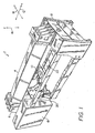
Fig. 1 is a perspective view of a laser cutting machine that has incorporated thereto the beam guide of the instant invention; -
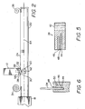
Fig. 2 is an semi-exposed top view of the guide beam of the instant invention; -
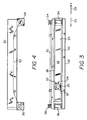
Fig. 3 is a side view of the guide beam ofFig. 2 with the aperture of the cover sheet particularly shown; -
Fig. 4 is a top view of the guide beam ofFig. 3 ; -
Fig. 5 is a cross-sectional view of the mechanism that couples the cover sheet to the open channel of the guide beam of the instant invention; -
Fig. 6 is a cross-sectional view of the grooves of the mounting mechanism ofFig. 4 with a portion of the cover sheet being shown to be movably inserted into one of the grooves of the mounting mechanism; and -
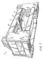
Fig. 7 is a perspective view of the laser cutting machine of the instant invention illustrating with particularity the underside of the cross beam to which the laser cutting head is movably mounted. - With reference to
Fig. 1 , alaser cutting machine 2 such as that described in the aforenoted related applications, the respective disclosures of which being incorporated by reference herein, is shown. Such laser cutting machine has anupper cross beam 4 mounted above two side supports 6 and 8. Mounted underneath the lower surface ofcross beam 4 is acutting head assembly 10 which movement is effected by driving mechanisms such as linear drives (not shown) mounted to the underside ofcross beam 4. As has been fully described in the aforenoted incorporated by reference applications, the laser cutting head that is mounted tolaser assembly 10 in turn is driven by servomechanisms positioned in lasercutting head assembly 10. Consequently, the laser cutting head is movable in both the x and y directions as indicated bydirectional arrows 12 and 14, respectively. In addition, by means of another servomechanism, the laser cutting head can be moved in a z direction as indicated bydirectional arrows 16. - To generate the laser beam for fabricating a worksheet, a laser generator (not shown but described in the aforenoted referenced applications) is provided inside a
laser generator housing 18 that is positioned adjacent toside support 6 oflaser machine 2. An enclosure in the form of atubular guide 20 extends fromhousing 18 in parallel relationship tocross beam 4. The other end ofbeam guide 20 is secured toside support 8. As best illustrated inFig. 1 ,tubular beam guide 20 consists of a tube that is rectangular in the exemplar embodiment shown. Of course,beam guide 20 can have other tubular configurations. In any event,tubular beam guide 20 has one of its sides, namely the side that faces lasercutting head assembly 10, open. Thus, anopen channel 22 extends substantially along the length ofbeam guide 20. - A semi-exposed plan view of
beam guide 20 is illustrated inFig. 2 . As shown, movably mounted overopen channel 22 is acover sheet 24 which may be made of a non-magnetic ferrous material such as for example stainless steel. Alternatively, a non-magnetic synthetic material, such as for example a Teflon-fiberglas based roll or mat, or other kinds of materials that are resistant to the heat from the laser beam traversing insidebeam guide 20 may also be used. - As best shown in
Fig. 3 ,cover sheet 24 has an opening oraperture 26 at a particular location thereat. To ensure rigidity, amount piece 28 is formed overaperture 26. A gasket, preferably made of rubber or other sealing material, is fitted to the edge ofaperture 26. Also formed inmount piece 28 is aguide hole 32. - Insofar as
cover sheet 24 is flexible, to ensure that it maintains some rigidity so as to prevent vacuum from being created insideguide beam 20 as cover sheet moves along the x direction, the respective ends ofcover sheet 24 are rolled intocorresponding coils aperture 26 is moved along the x direction, depending on whichway aperture 26 is being moved, the respective portions of the cover sheet atcoils aperture 26 were to move in the direction as indicated by directional arrow 12a, thenroll 36 would coil so as to roll up the excess portion ofcover sheet 24 that is being moved. At the same time, coil 34 uncoils so as to release the requisite amount ofcover sheet 24 for maintaining coverage of opening 22. Conversely, ifaperture 26 were to move in the direction as indicated by directional arrow 12b, thencoil 34 would coil so as to form additional rolls thereat whilecoil 36 would uncoil.Cover sheet 24 therefore continuously cover channel opening 22. - To ensure that
cover sheet 24 tightly coversopening 22, an upper mountingmember 38 is fixedly coupled to the edge ofbeam guide 20 that forms the upper edge ofopening 22. Similarly, a lower mounting member is fixedly coupled to the edge ofbeam guide 20 that forms the lower periphery ofopening 22. These upper and lower mountingmembers Fig. 5 . Insofar as both upper mountingmember 38 and lower mountingmember 40 are the same, for the sake of simplicity, only upper mountingmember 38 is shown inFig. 5 . - In particular, mounting
member 38 has anotch 42 that allows it to be matingly coupled to the edge ofbeam guide 20 that forms the upper periphery ofopen channel 22. Mountingmember 38 also has afirst groove 44 and asecond groove 46 separated by amid section 48. Once mountingmember 38 is fixedly mounted to the upper edge ofbeam guide 20 that forms the upper periphery ofopen channel 22,cover sheet 24 is slidably inserted intofirst groove 44. To provide the requisite friction for maintainingcover sheet 24 ingroove 44, arod 50 that may be made of rubber and which has a sufficient cross-sectional dimension is inserted intogroove 46 to thereby bias mid-section 48 againstcover sheet 24. The biasing force applied bymid-section 48 againstcover sheet 24 is such thatcover sheet 24, or more accurately an edge thereof, is held sufficiently sealingly tight withingroove 44 so as to prevent the laser beam from escaping frombeam guide 20 and yet at the same time provide sufficient slack to enablecover sheet 24 to move relative to groove 44. - Refer to
Figs. 3 and 4 . To maintaincoils wire 52 is wound aboutspindles Spindles cover sheet 24. Thus, by keeping a certain pretension inwire 52, slacks are taken out fromcoils - The coupling of laser cutting assembly to
beam guide 20 is best illustrated with reference toFig. 2 . As shown, a tube orconduit 58 extends from laser cuttinghead assembly 10 to mate withaperture 26, and to extend intobeam guide 20. By means ofgasket 30,tube 58 forms a seal tight relationship withcover sheet 24. Coupled totube 58 is amirror assembly 60 that has itslaser mirror 62 in alignment with the laser beam output from the laser generator that travels along the axis designated as 64.Mirror 62 is positioned relative totube 58 so that it reflects the intercepted laser beam totube 58, and therefore tolaser assembly 10. The redirecting the laser beam in laser cuttinghead assembly 10 to the laser cutting head is described in the above-referenced application and therefore will not discussed herein. To effect movement oftube 58 and therefore the sliding movement ofcover sheet 24 alongopen channel 22, aguide pin 66 matingly couples laser cuttinghead assembly 10 to mountingplate 28 by means ofguide hole 32. Thus, as laser cuttinghead assembly 10 is driven alongcross beam 4,tube 58 is moved in lockstep therewith. At the same time,cover sheet 24 is slidably moved withcoils cover sheet 24. - The same principle with which beam guide 20 is covered by
cover sheet 24 to reduce the possibility that dust and dirt may be sucked intobeam guide 20 is equally applicable to the movement oflaser head assembly 10 and the movement of the laser head relative tolaser head assembly 10. As shown in the perspective view oflaser cutting machine 2 ofFig. 7 , laser cuttinghead assembly 10 is mounted to theunderside 68 ofcross beam 4. As was mentioned previously, the movement of laser cuttinghead assembly 10 is effected by servomechanisms such as for example linear drives (not shown) that are mounted to the underside ofcross beam 4. To prevent dirt from accumulating onto the linear drives, acover sheet 70, which may be made of the same material and work the same way as previously described, is superposed overunderside 68 so as to isolate the linear drive mechanisms from the dust and dirt. Alternatively, a bevel-like cover may also be used. It is possible to use bevel-like cover 70 in this instance because there is a sufficient large opening at both ends ofcross beam 4 to which laser cuttinghead assembly 10 would never reach so that there is scant possibility that a vacuum could be created incross beam 4. - As further shown in
Fig. 7 , alaser cutting head 72 is mounted under laser cuttinghead assembly 10 for movement along the y direction as indicated. Insofar aslaser cutting head 72 is also driven by a linear drive mechanism such as 74, to insulate that linear drive mechanism from exposure to dust and dirt, a cover that operates by using the same principle as discussed previously may also be placed overdrive mechanism 74. InFig. 7 , for the sake of simplicity,beam guide 22 andlaser generator housing 18 are not shown. - Inasmuch as the present invention is subject to many variations, modifications and changes in detail, it is intended that all matter described throughout this specification and shown in the accompanying drawings be interpreted as illustrative only and not in a limiting sense. Accordingly, it is intended that the invention is limited only by the scope of the hereto appended claims.
Claims (10)
- A laser beam guide, comprising:a tubular guide (20) for providing a path along which a laser beam traverses, said guide having one open side along its length,a movable cover (24) slidably mounted to upper and lower members (38, 40) fixedly coupled to the respective upper and lower edges of the opening (22) of said open side so as to cover the open side of said guide to prevent dusts or other contaminants from entering said guide, said cover movable bidirectionally over said open side, said cover having an aperture (26) through which said laser beam is passable out of said guide, a mount (28) for connecting a laser cutting head (10) to said aperture to enable said laser beam to be output from said cutting head, said aperture and said cover movable with the movement of said cutting head bidirectionally along the travel length confined to said path so that said laser beam continues to pass through said aperture to said cutting head irrespective of where along said travel length said cutting head moves,characterized in that both ends of said cover are rolled into respective coils (34, 36); and wherein said coils are placed outside said guide (20) away from said path of said laser beam inside said guide (20).
- The laser beam guide according to claim 1, further comprising:a laser resonator for generating said laser beam;wherein said guide comprises a tube (20) extending along substantially the entire travel length of said cutting head; and
wherein said cover comprises a sheet of non-magnetic ferrous material covering the open side of said tube along which said cutting head moves. - The laser beam guide according to claim 1, wherein both ends of said cover are rolled into respective coils (34, 36); and
wherein as said cover is moved relative to said guide, one of said respective coils unrolls while the other of said coils increases the number of rolls thereat so that the length of said cover relative to said travel length remains constant. - The laser beam guide according to claim 1, further comprising:at least one mounting means (38, 40) positioned along the length of said guide, said cover being movably secured to said mounting means so that the movement of said cover is confined with respect to said guide.
- The laser beam guide according to claim 4, wherein said guide comprises a tube (20); and
wherein said mounting means comprises a section coupled longitudinally to said tube, said section having at least one groove (44) extending longitudinally along substantially the entire length thereof, said cover being movably fitted edgewise into said groove so as to be movable relative to said section, said groove providing sufficiently seal tight contact with said section for confining said laser beam within said tube. - The laser beam guide according to claim 5, wherein said section further includes an other groove (46) formed substantially in parallel to said one groove so that a mid-section (48) is formed between said grooves, said laser beam guide further comprising:a body of a sufficient cross sectional dimension (50) fitted into said other groove to force said mid-section towards said one groove to thereby sealingly hold the edge of said cover within said one groove to prevent said laser beam from escaping from said tube but yet with enough slack to allow said cover to move relative to said one groove.
- The laser beam guide according to claim 1, further comprising:two mounting sections (38, 40) each positioned longitudinally along said guide, said mounting sections being spaced from each other for accepting said cover therebetween, each edge of said cover movably secured by a corresponding one of said mounting sections so that said cover is movable between said mounting sections relative to said guide.
- The laser beam guide according to claim 1, further comprising:a rubber gasket (32) mounted to said aperture for providing a seal tight passage through which said laser beam passes.
- The laser beam guide according to claim 1, further comprising:a mirror (62) mounted relative to said mount and movable along the path of said laser beam for redirecting said laser beam from said guide to said cutting head through said mount.
- The laser beam guide according to claim 1, wherein said cover comprises a sheet of non-magnetic ferrous material covering the open side of said guide along which said cutting head moves.
Applications Claiming Priority (3)
| Application Number | Priority Date | Filing Date | Title |
|---|---|---|---|
| US09/433,966 US6310317B1 (en) | 1999-11-04 | 1999-11-04 | Laser beam guide |
| US433966 | 1999-11-04 | ||
| PCT/IB2000/001584 WO2001032350A1 (en) | 1999-11-04 | 2000-11-02 | Laser beam guide |
Publications (2)
| Publication Number | Publication Date |
|---|---|
| EP1232037A1 EP1232037A1 (en) | 2002-08-21 |
| EP1232037B1 true EP1232037B1 (en) | 2009-03-18 |
Family
ID=23722285
Family Applications (1)
| Application Number | Title | Priority Date | Filing Date |
|---|---|---|---|
| EP00969754A Expired - Lifetime EP1232037B1 (en) | 1999-11-04 | 2000-11-02 | Laser beam guide |
Country Status (7)
| Country | Link |
|---|---|
| US (1) | US6310317B1 (en) |
| EP (1) | EP1232037B1 (en) |
| AT (1) | ATE425838T1 (en) |
| AU (1) | AU7940100A (en) |
| DE (1) | DE60041828D1 (en) |
| DK (1) | DK1232037T3 (en) |
| WO (1) | WO2001032350A1 (en) |
Families Citing this family (7)
| Publication number | Priority date | Publication date | Assignee | Title |
|---|---|---|---|---|
| JP4527415B2 (en) * | 2004-02-18 | 2010-08-18 | ヤマザキマザック株式会社 | Laser processing machine |
| JP5014614B2 (en) * | 2005-10-26 | 2012-08-29 | ヤマザキマザック株式会社 | Laser processing machine optical path system sealing device |
| JP5014615B2 (en) * | 2005-10-31 | 2012-08-29 | ヤマザキマザック株式会社 | Laser processing machine dust path system |
| EP2346641B1 (en) * | 2008-11-18 | 2018-04-11 | L'Air Liquide Société Anonyme pour l'Etude et l'Exploitation des Procédés Georges Claude | Support table frame for high speed laser blanking |
| EP2355951A1 (en) | 2008-11-19 | 2011-08-17 | L'Air Liquide Société Anonyme pour l'Etude et l'Exploitation des Procédés Georges Claude | A process for laser cutting a metal plate |
| CN103394916B (en) * | 2013-08-07 | 2016-03-02 | 吴振泉 | Adopt uncoiling blanking production equipment and the processing method of laser cutting technique |
| US10026540B2 (en) * | 2014-04-02 | 2018-07-17 | Vishay Dale Electronics, Llc | Magnetic components and methods for making same |
Citations (3)
| Publication number | Priority date | Publication date | Assignee | Title |
|---|---|---|---|---|
| US2190213A (en) * | 1937-12-15 | 1940-02-13 | Henry F Meyer | Way guard for machine tools |
| US4694733A (en) * | 1985-11-08 | 1987-09-22 | Greenco Corporation | Cable shield for a rodless cylinder |
| US5427619A (en) * | 1993-10-06 | 1995-06-27 | Sames S.A. | Coating product sprayer device forming an overhead or lateral machine |
Family Cites Families (6)
| Publication number | Priority date | Publication date | Assignee | Title |
|---|---|---|---|---|
| GB1235653A (en) * | 1969-01-10 | 1971-06-16 | Nat Res Dev | Improvements relating to cutting processes employing a laser |
| US5051558A (en) | 1989-03-20 | 1991-09-24 | Sukhman Yefim P | Laser material processing apparatus and method therefore |
| US4973819A (en) * | 1989-09-26 | 1990-11-27 | Mcdonnell Douglas Corporation | Gantry with a laser mounted numerically controlled carriage |
| US5915823A (en) * | 1995-10-19 | 1999-06-29 | Simon; Jerome H. | Central source light distribution system and components for maintaining beam continuity to adjustably positionable remote illumination directors |
| US5854460A (en) | 1996-05-07 | 1998-12-29 | Cincinnati Incorporated | Linear motor driven laser cutting machine |
| BE1010446A3 (en) | 1996-07-31 | 1998-08-04 | Engineering Support Nv | Casing for transferring a laser bundle across a variable distance |
-
1999
- 1999-11-04 US US09/433,966 patent/US6310317B1/en not_active Expired - Lifetime
-
2000
- 2000-11-02 DK DK00969754T patent/DK1232037T3/en active
- 2000-11-02 WO PCT/IB2000/001584 patent/WO2001032350A1/en not_active Ceased
- 2000-11-02 DE DE60041828T patent/DE60041828D1/en not_active Expired - Lifetime
- 2000-11-02 AT AT00969754T patent/ATE425838T1/en not_active IP Right Cessation
- 2000-11-02 EP EP00969754A patent/EP1232037B1/en not_active Expired - Lifetime
- 2000-11-02 AU AU79401/00A patent/AU7940100A/en not_active Abandoned
Patent Citations (3)
| Publication number | Priority date | Publication date | Assignee | Title |
|---|---|---|---|---|
| US2190213A (en) * | 1937-12-15 | 1940-02-13 | Henry F Meyer | Way guard for machine tools |
| US4694733A (en) * | 1985-11-08 | 1987-09-22 | Greenco Corporation | Cable shield for a rodless cylinder |
| US5427619A (en) * | 1993-10-06 | 1995-06-27 | Sames S.A. | Coating product sprayer device forming an overhead or lateral machine |
Also Published As
| Publication number | Publication date |
|---|---|
| WO2001032350A1 (en) | 2001-05-10 |
| DK1232037T3 (en) | 2009-06-15 |
| DE60041828D1 (en) | 2009-04-30 |
| AU7940100A (en) | 2001-05-14 |
| EP1232037A1 (en) | 2002-08-21 |
| US6310317B1 (en) | 2001-10-30 |
| ATE425838T1 (en) | 2009-04-15 |
Similar Documents
| Publication | Publication Date | Title |
|---|---|---|
| US6310317B1 (en) | Laser beam guide | |
| US5539987A (en) | X-Y carriage moving system | |
| JP3261741B2 (en) | Door device | |
| JP7113629B2 (en) | Cable transfer device | |
| US20130032580A1 (en) | Optical path structure of laser processing machine | |
| EP1566235B1 (en) | Laser beam working machine with first and second beam guide portions for shortening the length of the optical path, the latter being held constant during laser processing | |
| EP1162046A2 (en) | X-Y axes cutting machine | |
| EP1779959B1 (en) | Seal device of light path system in laser beam machine | |
| JPH0235425Y2 (en) | ||
| JP3695841B2 (en) | Winding cover device for machine | |
| JP4833013B2 (en) | Extension protection device and installation structure of the extension protection device | |
| KR950005872B1 (en) | Movable table having movable-area covering mechanism | |
| EP1779960B1 (en) | Dustproof device of light path system in laser beam machine | |
| JP2000233292A (en) | Laser processing machine | |
| JPH0224196B2 (en) | ||
| JPH0611008A (en) | Dust prevention mechanism for linear motion device | |
| KR950007782Y1 (en) | Robot drive with improved protection cover | |
| JPH0536157B2 (en) | ||
| WO2025013941A1 (en) | Shutter device, cover body, and method for attaching cover body | |
| JP2001317606A (en) | Dust proof device for moving mechanism | |
| JPS5976745A (en) | X-y table | |
| JPS61250432A (en) | Robot for clean room | |
| JP2598430Y2 (en) | Sliding surface protection device for machine tools | |
| JPH04217444A (en) | Preventing and removing device for chip of machine tool | |
| NL1010784C1 (en) | Linear translation movement with limited range |
Legal Events
| Date | Code | Title | Description |
|---|---|---|---|
| PUAI | Public reference made under article 153(3) epc to a published international application that has entered the european phase |
Free format text: ORIGINAL CODE: 0009012 |
|
| 17P | Request for examination filed |
Effective date: 20020603 |
|
| AK | Designated contracting states |
Kind code of ref document: A1 Designated state(s): AT BE CH CY DE DK ES FI FR GB GR IE IT LI LU MC NL PT SE |
|
| AX | Request for extension of the european patent |
Free format text: AL;LT;LV;MK;RO;SI |
|
| 17Q | First examination report despatched |
Effective date: 20040618 |
|
| 17Q | First examination report despatched |
Effective date: 20040618 |
|
| 17Q | First examination report despatched |
Effective date: 20040618 |
|
| GRAP | Despatch of communication of intention to grant a patent |
Free format text: ORIGINAL CODE: EPIDOSNIGR1 |
|
| GRAS | Grant fee paid |
Free format text: ORIGINAL CODE: EPIDOSNIGR3 |
|
| GRAA | (expected) grant |
Free format text: ORIGINAL CODE: 0009210 |
|
| AK | Designated contracting states |
Kind code of ref document: B1 Designated state(s): AT BE CH CY DE DK ES FI FR GB GR IE IT LI LU MC NL PT SE |
|
| REG | Reference to a national code |
Ref country code: GB Ref legal event code: FG4D |
|
| REG | Reference to a national code |
Ref country code: CH Ref legal event code: EP |
|
| REG | Reference to a national code |
Ref country code: IE Ref legal event code: FG4D |
|
| REF | Corresponds to: |
Ref document number: 60041828 Country of ref document: DE Date of ref document: 20090430 Kind code of ref document: P |
|
| REG | Reference to a national code |
Ref country code: DK Ref legal event code: T3 |
|
| REG | Reference to a national code |
Ref country code: SE Ref legal event code: TRGR |
|
| PG25 | Lapsed in a contracting state [announced via postgrant information from national office to epo] |
Ref country code: AT Free format text: LAPSE BECAUSE OF FAILURE TO SUBMIT A TRANSLATION OF THE DESCRIPTION OR TO PAY THE FEE WITHIN THE PRESCRIBED TIME-LIMIT Effective date: 20090318 |
|
| PG25 | Lapsed in a contracting state [announced via postgrant information from national office to epo] |
Ref country code: ES Free format text: LAPSE BECAUSE OF FAILURE TO SUBMIT A TRANSLATION OF THE DESCRIPTION OR TO PAY THE FEE WITHIN THE PRESCRIBED TIME-LIMIT Effective date: 20090629 Ref country code: PT Free format text: LAPSE BECAUSE OF FAILURE TO SUBMIT A TRANSLATION OF THE DESCRIPTION OR TO PAY THE FEE WITHIN THE PRESCRIBED TIME-LIMIT Effective date: 20090826 |
|
| PLBE | No opposition filed within time limit |
Free format text: ORIGINAL CODE: 0009261 |
|
| STAA | Information on the status of an ep patent application or granted ep patent |
Free format text: STATUS: NO OPPOSITION FILED WITHIN TIME LIMIT |
|
| 26N | No opposition filed |
Effective date: 20091221 |
|
| PG25 | Lapsed in a contracting state [announced via postgrant information from national office to epo] |
Ref country code: MC Free format text: LAPSE BECAUSE OF NON-PAYMENT OF DUE FEES Effective date: 20091130 |
|
| REG | Reference to a national code |
Ref country code: CH Ref legal event code: PL |
|
| GBPC | Gb: european patent ceased through non-payment of renewal fee |
Effective date: 20091102 |
|
| REG | Reference to a national code |
Ref country code: FR Ref legal event code: ST Effective date: 20100730 |
|
| PG25 | Lapsed in a contracting state [announced via postgrant information from national office to epo] |
Ref country code: FR Free format text: LAPSE BECAUSE OF NON-PAYMENT OF DUE FEES Effective date: 20091130 Ref country code: GR Free format text: LAPSE BECAUSE OF FAILURE TO SUBMIT A TRANSLATION OF THE DESCRIPTION OR TO PAY THE FEE WITHIN THE PRESCRIBED TIME-LIMIT Effective date: 20090619 Ref country code: IE Free format text: LAPSE BECAUSE OF NON-PAYMENT OF DUE FEES Effective date: 20091102 Ref country code: LI Free format text: LAPSE BECAUSE OF NON-PAYMENT OF DUE FEES Effective date: 20091130 Ref country code: CH Free format text: LAPSE BECAUSE OF NON-PAYMENT OF DUE FEES Effective date: 20091130 |
|
| PG25 | Lapsed in a contracting state [announced via postgrant information from national office to epo] |
Ref country code: GB Free format text: LAPSE BECAUSE OF NON-PAYMENT OF DUE FEES Effective date: 20091102 |
|
| PG25 | Lapsed in a contracting state [announced via postgrant information from national office to epo] |
Ref country code: LU Free format text: LAPSE BECAUSE OF NON-PAYMENT OF DUE FEES Effective date: 20091102 |
|
| PG25 | Lapsed in a contracting state [announced via postgrant information from national office to epo] |
Ref country code: CY Free format text: LAPSE BECAUSE OF FAILURE TO SUBMIT A TRANSLATION OF THE DESCRIPTION OR TO PAY THE FEE WITHIN THE PRESCRIBED TIME-LIMIT Effective date: 20090318 |
|
| PGFP | Annual fee paid to national office [announced via postgrant information from national office to epo] |
Ref country code: DK Payment date: 20121112 Year of fee payment: 13 |
|
| PGFP | Annual fee paid to national office [announced via postgrant information from national office to epo] |
Ref country code: DE Payment date: 20121031 Year of fee payment: 13 Ref country code: FI Payment date: 20121112 Year of fee payment: 13 |
|
| PGFP | Annual fee paid to national office [announced via postgrant information from national office to epo] |
Ref country code: IT Payment date: 20121110 Year of fee payment: 13 Ref country code: BE Payment date: 20121113 Year of fee payment: 13 Ref country code: SE Payment date: 20121113 Year of fee payment: 13 |
|
| PGFP | Annual fee paid to national office [announced via postgrant information from national office to epo] |
Ref country code: NL Payment date: 20121110 Year of fee payment: 13 |
|
| BERE | Be: lapsed |
Owner name: LILLBACKA JETAIR OY Effective date: 20131130 |
|
| REG | Reference to a national code |
Ref country code: NL Ref legal event code: V1 Effective date: 20140601 |
|
| REG | Reference to a national code |
Ref country code: DK Ref legal event code: EBP Effective date: 20131130 |
|
| REG | Reference to a national code |
Ref country code: SE Ref legal event code: EUG |
|
| PG25 | Lapsed in a contracting state [announced via postgrant information from national office to epo] |
Ref country code: SE Free format text: LAPSE BECAUSE OF NON-PAYMENT OF DUE FEES Effective date: 20131103 Ref country code: DE Free format text: LAPSE BECAUSE OF NON-PAYMENT OF DUE FEES Effective date: 20140603 Ref country code: IT Free format text: LAPSE BECAUSE OF NON-PAYMENT OF DUE FEES Effective date: 20131102 Ref country code: NL Free format text: LAPSE BECAUSE OF NON-PAYMENT OF DUE FEES Effective date: 20140601 Ref country code: FI Free format text: LAPSE BECAUSE OF NON-PAYMENT OF DUE FEES Effective date: 20131102 |
|
| REG | Reference to a national code |
Ref country code: DE Ref legal event code: R119 Ref document number: 60041828 Country of ref document: DE Effective date: 20140603 |
|
| PG25 | Lapsed in a contracting state [announced via postgrant information from national office to epo] |
Ref country code: BE Free format text: LAPSE BECAUSE OF NON-PAYMENT OF DUE FEES Effective date: 20131130 |
|
| PG25 | Lapsed in a contracting state [announced via postgrant information from national office to epo] |
Ref country code: DK Free format text: LAPSE BECAUSE OF NON-PAYMENT OF DUE FEES Effective date: 20131130 |