EP1231688A2 - Method for manufacturing spark plug and apparatus for carrying out the same - Google Patents
Method for manufacturing spark plug and apparatus for carrying out the same Download PDFInfo
- Publication number
- EP1231688A2 EP1231688A2 EP02250652A EP02250652A EP1231688A2 EP 1231688 A2 EP1231688 A2 EP 1231688A2 EP 02250652 A EP02250652 A EP 02250652A EP 02250652 A EP02250652 A EP 02250652A EP 1231688 A2 EP1231688 A2 EP 1231688A2
- Authority
- EP
- European Patent Office
- Prior art keywords
- spark plug
- illumination
- spark gap
- spark
- manufacturing
- Prior art date
- Legal status (The legal status is an assumption and is not a legal conclusion. Google has not performed a legal analysis and makes no representation as to the accuracy of the status listed.)
- Granted
Links
Images





Classifications
-
- H—ELECTRICITY
- H01—ELECTRIC ELEMENTS
- H01T—SPARK GAPS; OVERVOLTAGE ARRESTERS USING SPARK GAPS; SPARKING PLUGS; CORONA DEVICES; GENERATING IONS TO BE INTRODUCED INTO NON-ENCLOSED GASES
- H01T13/00—Sparking plugs
- H01T13/20—Sparking plugs characterised by features of the electrodes or insulation
-
- H—ELECTRICITY
- H01—ELECTRIC ELEMENTS
- H01T—SPARK GAPS; OVERVOLTAGE ARRESTERS USING SPARK GAPS; SPARKING PLUGS; CORONA DEVICES; GENERATING IONS TO BE INTRODUCED INTO NON-ENCLOSED GASES
- H01T21/00—Apparatus or processes specially adapted for the manufacture or maintenance of spark gaps or sparking plugs
- H01T21/02—Apparatus or processes specially adapted for the manufacture or maintenance of spark gaps or sparking plugs of sparking plugs
Definitions
- the present invention relates to a method for manufacturing a spark plug and an apparatus for carrying out the same.
- a spark gap is formed and adjusted in the following manner: after a ground electrode is subjected to preliminary pressing, the ground electrode is repeatedly subjected to pressing while the gap is monitored by use of a CCD camera or a like device, until the gap reaches a target value.
- a tip portion of a spark plug is irradiated with light emitted from illumination means which is located opposite the photographing means with respect to the tip portion, to thereby produce a sharp silhouette of the electrodes.
- An object of the present invention is to provide a method for manufacturing a spark plug, capable of photographing a center electrode and a ground electrode such that edges of the electrodes are detected at high accuracy, and capable of manufacturing a spark plug at high accuracy on the basis of a photographed image of the electrodes, as well as to provide an apparatus for carrying out the same.
- the present invention provides a method for manufacturing a spark plug comprising a center electrode disposed within an insulator, a metallic shell disposed outside the insulator, and a ground electrode, one end of the ground electrode being joined to an end face of the metallic shell, an opposite end portion of the ground electrode being bent such that a side surface of the opposite end portion faces an end face of the center electrode so as to form a spark gap between the side surface and the end face, the method comprising:
- the present invention further provides an apparatus for carrying out the method.
- a light shield can be used to block out illumination rays which are directed toward the photographing means so as to diverge from a spark gap after passing through the spark gap, thereby effectively preventing reflections of the illumination rays (i.e., effectively preventing reflections from an edge portion of the surface of the center electrode facing the photographing means and reflections from an edge portion of the surface of the ground electrode facing the photographing means).
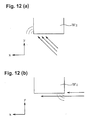
- illumination rays which enter the spark gap at a greater incident angle specifically, at a greater incident angle with respect to a direction perpendicular to the axial direction of the center electrode
- the x direction is the direction along which the illumination means and the photographing means face each other
- the y direction is the axial direction of the center electrode.
- the light shield can also be a mask having an aperture having either a fixed or variable opening.
- the above-described method enables easy adjustment of the axial distance of an emission region through which illumination rays are emitted.
- the axial distance of the emission region can be adjusted so as to be suited for the spark gap. Since illumination rays which enter the spark gap at a large angle can be blocked out, only parallel rays as shown in Fig. 12(b) or near parallel rays pass through the spark gap, thereby restraining reflections of diffracted rays from the edge portions of the electrodes facing the photographing means.
- the image thus obtained provides highly accurate silhouettes of the center and ground electrodes, thereby enabling an accurate value of the gap to be determined.
- illumination rays may be emitted so as to pass by a light shield disposed between the spark gap and a light source provided on the illumination means. Emission of illumination rays via the light shield enables a desired illumination range to be attained regardless of the size of the light source. Further, the following arrangement may be employed: light shields are disposed along the axial direction of a spark plug on axially opposite sides of the spark gap so as to define therebetween an emission region for allowing illumination rays to pass through; and the distance as measured along the axial direction between the edges of the light shields which face the emission region is adjusted to 0.5 mm to 30 mm.
- This adjustment effectively restrains reflections of diffracted rays from the edge portions of the electrodes while maintaining a sufficient quantity of light for obtaining an image of the center and ground electrodes.
- the quantity of light is insufficient for obtaining the image.
- the axial distance is in excess of 30 mm, illumination rays which enter the spark gap at a large incident angle increase, potentially causing an increase in the amount and range of reflections from the exit edge portions of the electrodes. Such adjustment prevents these problems.
- parallel rays emitted from a parallel-ray emission means may be employed so as to restrain divergence of illumination rays from the spark gap. Since illumination rays enter the spark gap at an incident angle of substantially zero, illumination rays that directly irradiate an exit edge portion of an electrode can be greatly reduced, thereby effectively restraining diffraction of rays around the edge portion.
- FIGs. 1(a) and 1(b) are a plan view and a side view, respectively, schematically showing an embodiment of an apparatus for manufacturing a spark plug (hereinafter, also referred to as a manufacturing apparatus) of the present invention.
- a manufacturing apparatus 1 includes a linear conveyor 300, which serves as a conveyance mechanism for intermittently conveying spark plugs to undergo working (hereinafter, also called a workpiece) W along a conveyance path C (a linear path in the present embodiment).
- Working stations for forming a spark gap of a workpiece W i.e., a workpiece loading mechanism 11 for loading a spark plug to undergo working; a ground electrode positioning mechanism 12 for positioning the ground electrode of the workpiece W at a predetermined position; a tip face position measuring unit 13 for measuring the position of the tip face of a center electrode; a preliminary bending unit 14 for preliminarily bending the ground electrode; a main bending unit 15 for performing main bending work on the ground electrode; a workpiece ejection mechanism 16 for ejecting the workpiece W which has undergone the bending work; and a rejected-product ejection mechanism 17, are arranged in this order in the direction of conveyance along the conveyance path C.
- the linear conveyor 300 includes a chain 301, which serves as a circulating member, and carriers 302, which are removably loaded with the corresponding workpieces W and are attached to the chain 301 at predetermined intervals.
- the chain 301 is intermittently driven in a circulating condition by means of a conveyor drive motor 24, the carriers 302; i.e., the workpieces W, are intermittently conveyed along the conveyance path C.
- the workpiece W includes a cylindrical metallic shell W 3 ; an insulator W 4 , which is fitted into the metallic shell W 3 such that front and rear end portions thereof project from the metallic shell W 3 ; a center electrode W 1 , which is axially inserted into the insulator W 4 ; and a ground electrode W 2 , whose one end is joined to the metallic shell W 3 by welding or a like process and which extends along the axial direction of the center electrode W 1 .
- the ground electrode W 2 undergoes bending work, which will be described later.
- a free end portion thereof is bent toward the tip face of the center electrode W 1 so as to form a spark gap, whereby the workpiece W becomes a parallel-electrode-type spark plug.
- a cylindrical holder 23 is integrally mounted on the top surface of each carrier 302 such that the top end thereof is open.
- the workpiece W is removably inserted, from a rear end thereof, into the holder 23.
- a hexagonal portion W 6 of the metallic shell W 3 is supported by a circumferential edge portion of an opening of the holder 23.
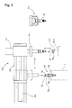
- the workpiece loading mechanism 11, the workpiece ejection mechanism 16, and the rejected-product ejection mechanism 17 shown in Fig. 1 are each configured in the form of, for example, a transfer mechanism as shown in Fig. 2 for transferring the workpiece W between a workpiece supply section or a workpiece ejection section (provided at position J in Fig. 2) located laterally away from the conveyance path C of the linear conveyor 300 (Fig. 1) and the holder 23 which is positioned within the loading or ejection mechanism.
- the transfer mechanism 35 includes a chuck hand mechanism 36, which is held so as to be vertically movable through activation by an air cylinder 37, and a reciprocative drive mechanism 39 for causing the chuck hand mechanism 36 to reciprocate in a radial direction of a circumferential path C by use of an air cylinder 38.
- the ground electrode positioning mechanism 12 is adapted to position the ground electrode W 2 at a predetermined position by rotating a spark plug with an actuator, such as a motor.
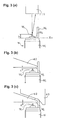
- the tip face position measuring unit 13 measures the position of the tip face of the center electrode W 1 prior to preliminary bending, which will be described later, and includes a position sensor 115 as shown in Fig. 3(a).
- the workpiece W is held, in a standing condition with the ground electrode W 2 facing up, by the holder 23, which is mounted on the linear conveyor 300 to thereby be fixed in height.
- the position sensor 115 e.g., a laser displacement sensor
- the position sensor 115 is held at a constant height by a frame used for measuring the height of the tip face and thus measures the position of the tip face of the center electrode W 1 of a loaded workpiece W.
- a preliminary bending spacer 42 is positioned, on the basis of the position of the tip face of the center electrode W 1 of the workpiece W detected by the position sensor 115, such that a substantially constant gap d is formed between the tip face and the bottom of the preliminary bending space 42. Then, a free end portion of the ground electrode W 2 is pressed against the preliminary bending spacer 42 using a bending punch 43 such that the free end portion faces the center electrode W 1 via the preliminary bending spacer 42.
- the bending punch 43 is driven by an unillustrated punch drive unit, such as an air cylinder, so as to move toward and away from the ground electrode W 2 for preliminary bending.
- the bending punch 43 presses the ground electrode W 2 against the preliminary bending spacer 42 to thereby carry out preliminary bending of the ground electrode W 2 .
- the electrodes are unlikely to suffer a defect, such as a chip or a scratch, with resultant attainment of high yield.
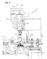
- Fig. 4 shows an example of the main bending unit 15.
- the workpiece W is introduced into the main bending unit 15 by means of the linear conveyor 300 and is then positioned at a predetermined working position.
- a gap photographing-analyzing unit 3 and a bending mechanism 5, which mainly constitutes gap adjustment means, are disposed on opposite sides of the conveyance path of the linear conveyor 300 such that the unit 3, the mechanism 5, and the working position for the workpiece W are aligned.
- the gap photographing-analyzing unit (hereinafter, also called a photographing-analyzing unit) 3 is mainly used for photographing and includes a camera 4, which is supported on a frame 22 and serves as photographing means, and an unillustrated analyzer connected to the camera 4.
- the analyzer may include an I/O port and components connected to the I/O port, such as a CPU, a ROM, and a RAM.
- the camera 4 assumes the form of, for example, a CCD camera which includes a two-dimensional CCD sensor as an image detector, and is adapted to laterally photograph the center electrode W 1 of a workpiece, the ground electrode W 2 , which faces the center electrode W 1 , and a spark gap g formed between the center electrode W 1 and the ground electrode W 2 .
- the bending mechanism 5 is configured, for example, such that a body casing 52 is attached to the front end face of a cantilever frame 51 mounted on a base 50 of the unit.
- a movable base 53 is accommodated within the body casing 52 in a vertically movable condition.
- a press punch 54 is attached to the movable base 53 via a rod 58 so as to project from the bottom end face of the body casing 52.
- a screw shaft (e.g., a ball screw) 55 is screw-engaged from above with a female screw portion 53a of the movable base 53.
- the screw shaft 55 is rotated in regular and reverse directions by means of a press punch drive motor 56 to thereby move the press punch 54 toward and away from the ground electrode W 2 of the workpiece W.
- the press punch 54 can be held at any height corresponding to a stop position.
- the rotating force of the press punch drive motor 56 is transmitted to the screw shaft 55 via a timing pulley 56a, a timing belt 57, and a timing pulley 55a.
- the press punch 54 is caused to approach and press the ground electrode W 2 which is preliminarily bent, for example, such that the free end thereof faces obliquely upward, thereby performing main bending work (a gap adjustment step) such that a free end portion of the ground electrode W 2 becomes substantially parallel to the tip face of the center electrode W 1 , and adjusting the spark discharge gap to a target value.
- main bending work a gap adjustment step
- the workpiece W is fixedly held, from opposite sides with respect to the axial direction, between holder members 60 and 61.
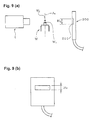
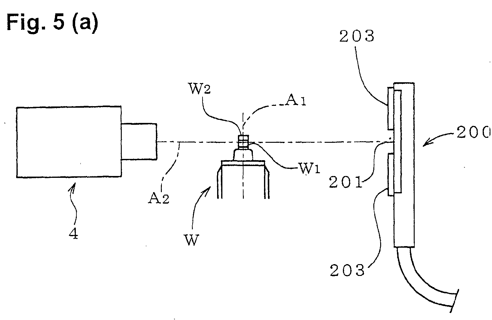
- an illumination device 200 is disposed opposite a tip portion of the workpiece W (spark plug), in which a spark gap is to be formed, such that illumination rays pass through the spark gap.
- the embodiment of Fig. 5 employs a planar-light-emission-type illumination device.
- light shields 203 are disposed between a light source 201 of the illumination device 200 and the tip portion of the spark plug in order to partially block out illumination rays which are directed toward the tip portion of the spark plug from the light source 201 but which diverge from the spark gap.
- the illumination rays which diverge from the spark gap refer to illumination rays which are directed to the tip portion of the spark plug from the light source but which do not pass through the spark gap in the lateral direction (the lateral direction refers to the direction perpendicular to the axial direction A 1 (in Fig. 6, the direction represented by the dash-and-dot line A 2 )). Accordingly, as shown in Fig. 6, most illumination rays which would otherwise pass through the spark gap g in an oblique direction (e.g., the direction of arrow B) are blocked by the light shields 203.
- the light shield 203 is disposed on at least one side of a spark gap with respect to the axial direction of a center electrode.
- the light shields 203 are disposed on opposite sides of the spark gap with respect to the axial direction of the center electrode so as to define therebetween an emission region for allowing illumination rays to pass through.
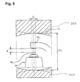
- the distance H 1 as measured along the axial direction between edges of the light shields 203 which face the emission region is adjusted to 0.5 mm to 30 mm. In the present embodiment, the distance H 1 is adjusted to 20 mm.
- the mutually facing edges of the light shields 203 are parallel to each other.
- the light shields 203 are disposed in the vicinity of the light source 201 (specifically, for example, so as to cover the light-emitting face of the light source 201 in a contact or near contact state).
- the light shields 203 may be disposed at an intermediate position between the workpiece W and the light source 201.
- the light shields 203 are disposed at a position biased toward the workpiece W (specifically, in the vicinity of the workpiece W).
- the light shields 203 are used in a manner similar to that of Fig. 5 or Fig. 7 except that the edges thereof are not parallel to each other.
- the edge-to-edge distance H 1 is 0.5 mm to 30 mm as measured within a section corresponding to the width of the tip face of the center electrode in an image as projected orthogonally on a virtual plane parallel to the axial direction and whose normal extends parallel to the facing direction of a photographing device and illumination means.
- the edge-to-edge distance is 0.5 mm to 30 mm as measured along the axial direction within a section corresponding to the width D of the center electrode (the width direction of the center electrode is perpendicular to the axial direction).
- the edges are curved such that the distance therebetween increases. However, when, as represented by the dash-and-dot line L, the edges are curved such that the distance therebetween decreases, or in the case of any other shape of the edges, the edge-to-edge distance can be similarly determined.
- the width of a light source itself may be adjusted.
- the emission region through which illumination rays are emitted is adjusted to 0.5 mm to 30 mm in distance H 2 as measured along the axial direction of the center electrode.
- the edge-to-edge distance can be set so as to fall within the above-mentioned range.
- the edge-to-edge distance can be determined by a method similar to that of Fig. 8.
- the edge-to-edge distance of the emission face is adjusted in a manner similar to that of Fig. 8 (i.e., the edge-to-edge distance of the emission face is adjusted to 0.5 mm to 30 mm as measured along the axial direction within a section corresponding to the width of the center electrode).
- the present embodiment uses a halogen lamp as illumination means.
- an LED, a sodium lamp, or the like may be used.
- the illumination means may be parallel-ray emission means for emitting parallel rays toward the tip end portion of the spark plug.
- the parallel-ray emission means may be configured, for example, such that parallel rays are emitted using fine slits.
- optical conversion means may be used for converting diffuse rays to parallel rays.
- the optical conversion means may assume the form of a louver having fine slits arranged at very fine intervals.
- the present invention is not limited thereto.
- a collimator or like device may be used for emitting parallel rays, or a light source of very high directivity, such as a laser beam, may be used.
- Fig. 10 shows an example in which rays emitted from a point light source are converted to parallel rays using a convex lens.
- the parallel-ray emission means may be combined with an illumination form in which light shields are provided as shown in Figs. 5, 7, and 8 or with an illumination form in which the width of emission of a light source itself is adjusted as shown in Fig. 9.
- a gap adjustment step which serves as the after-treatment step, is performed for adjusting the spark gap.
- the gap adjustment step is performed using the main bending unit 15 in the following manner.
- the press punch 54 which, as shown in Fig. 11(a), is caused by an unillustrated drive unit, such as a screw shaft mechanism, to vertically move toward and away from the ground electrode W 2 of the workpiece W positioned within the main bending unit 15
- an unillustrated drive unit such as a screw shaft mechanism
- a free end portion of the ground electrode W 2 is made substantially parallel to the tip face of the center electrode W 1 .
- the main bending work is carried out while the spark gap is being monitored using the camera 4.
- the spark discharge gap g is adjusted to a predetermined value.
- the press punch 54 is provided with a load cell at its tip. Upon detection of contact with an outside electrode, the press punch 54 performs bending work by an amount of displacement as instructed by an image unit (the analyzer mentioned previously), which is electrically connected to the camera 4 and which performs size measurement, etc.
- various specific methods are available for adjusting the spark gap on the basis of image information obtained from the photographing step. For example, a method for adjusting the spark gap in a stepwise manner as disclosed in Japanese Patent Application Laid-Open (kokai) No. 2000-164322 may be employed.
- the after-treatment step is not limited to a gap adjustment step.
- a defect control step for controlling defects on the basis of an image obtained through photographing may be employed.
- the defect control step may be implemented as a defective-product rejection step in which a product whose photographed image fails to conform to the criteria for a conforming product is rejected as a non-conforming product.
- a product data generation step may be employed in which product data regarding a photographed product are generated on the basis of an image of the product obtained by photographing.
- the product data generation step may employ the following method.
- a photographed product is judged defective from an image of the product obtained by photographing
- information about the defect in the photographed product information about whether or not defect is present, information about the type of defect, etc.
- basic product information regarding the photographed product product No. date of inspection, lot No., etc.
Landscapes
- Engineering & Computer Science (AREA)
- Manufacturing & Machinery (AREA)
- Spark Plugs (AREA)
- Image Analysis (AREA)
- Length Measuring Devices By Optical Means (AREA)
- Image Processing (AREA)
Abstract
Description
Claims (10)
- A method for manufacturing a spark plug comprising a center electrode disposed within an insulator, a metallic shell disposed outside the insulator, and a ground electrode, one end of the ground electrode being joined to an end face of the metallic shell, an opposite end portion of the ground electrode being bent such that a side surface of the opposite end portion faces an end face of the center electrode so as to form a spark gap between the side surface and the end face, said method comprising:photographing the spark gap with photographing means disposed at a position for receiving illumination rays which are emitted from illumination means in a manner which restrains divergence of illumination rays passing through the spark gap due to interaction with edges of the ground and/or center electrodes; andperforming a predetermined treatment on the basis of image information obtained from said photographing step.
- A method for manufacturing a spark plug according to claim 1, which comprises disposing a light shield between the spark gap and a light source of the illumination means.
- A method for manufacturing a spark plug according to claim 2, which comprises disposing at least two light shields along an axial direction of the spark plug on axially opposite sides of the spark gap so as to define therebetween an emission region for allowing the illumination rays to pass through, and
wherein a distance as measured along the axial direction between edges of the light shields which face the emission region is adjusted to be in the range of from 0.5 mm to 30 mm. - A method for manufacturing a spark plug according to any one of the previous claims, wherein said illumination means comprises a light source having an emission region of dimension in the range of from 0.5 mm to 30 mm as measured along the axial direction of the spark plug.
- A method for manufacturing a spark plug according to any one of the preceding claims, wherein the illumination rays emitted from the illumination means are parallel rays and the illumination means comprises parallel-ray emission means.
- An apparatus for manufacturing a spark plug comprising a center electrode disposed within an insulator, a metallic shell disposed outside the insulator, and a ground electrode, one end of the ground electrode being joined to an end face of the metallic shell, an opposite end portion of the ground electrode being bent such that a side surface of the opposite end portion faces an end face of the center electrode so as to form a spark gap between the side surface and the end face, said apparatus comprising:illumination means for emitting illumination rays in a manner which restrains divergence of illumination rays passing through the spark gap due to interaction with edges of the ground and/or center electrodes;photographing means disposed at a position for receiving the illumination rays which have passed through the spark gap; andafter-treatment means for performing a predetermined treatment on the basis of image information obtained from said photographing means.
- An apparatus for manufacturing a spark plug according to claim 6, which comprises a light shield disposed between the spark gap and a light source of said illumination means.
- An apparatus for manufacturing a spark plug according to claim 7, which comprises at least two light shields disposed along an axial direction of the spark plug on axially opposite sides of the spark gap so as to define therebetween an emission region for allowing the illumination rays to pass through, and
wherein a distance as measured along the axial direction between edges of the light shields which face the emission region is adjusted to be in the range of from 0.5 mm to 30 mm. - The apparatus for manufacturing a spark plug according to any one of claims 6 to 8, said illumination means comprising a light source having an emission region of dimension in the range of from 0.5 mm to 30 mm as measured along the axial direction of the spark plug.
- The apparatus for manufacturing a spark plug according to any one of claims 6 to 9, wherein the illumination rays emitted from said illumination means are parallel rays and the illumination means comprises parallel-ray emission means.
Applications Claiming Priority (2)
| Application Number | Priority Date | Filing Date | Title |
|---|---|---|---|
| JP2001024034 | 2001-01-31 | ||
| JP2001024034A JP2002231412A (en) | 2001-01-31 | 2001-01-31 | Spark plug manufacturing method and manufacturing apparatus |
Publications (3)
| Publication Number | Publication Date |
|---|---|
| EP1231688A2 true EP1231688A2 (en) | 2002-08-14 |
| EP1231688A3 EP1231688A3 (en) | 2006-04-26 |
| EP1231688B1 EP1231688B1 (en) | 2007-09-05 |
Family
ID=18889236
Family Applications (1)
| Application Number | Title | Priority Date | Filing Date |
|---|---|---|---|
| EP02250652A Expired - Lifetime EP1231688B1 (en) | 2001-01-31 | 2002-01-30 | Method for manufacturing spark plug and apparatus for carrying out the same |
Country Status (6)
| Country | Link |
|---|---|
| US (1) | US6695663B2 (en) |
| EP (1) | EP1231688B1 (en) |
| JP (1) | JP2002231412A (en) |
| KR (1) | KR100839286B1 (en) |
| CN (1) | CN100362711C (en) |
| DE (1) | DE60222194T2 (en) |
Families Citing this family (16)
| Publication number | Priority date | Publication date | Assignee | Title |
|---|---|---|---|---|
| US7581998B2 (en) | 2005-09-08 | 2009-09-01 | Ngk Spark Plug Co., Ltd. | Method for regulating aground electrode position in spark plug |
| WO2010041599A1 (en) * | 2008-10-06 | 2010-04-15 | 日本特殊陶業株式会社 | Method for manufacturing spark plug and device for manufacturing spark plug |
| JP4705147B2 (en) * | 2008-11-17 | 2011-06-22 | 日本特殊陶業株式会社 | Spark plug and spark plug assembly |
| EP2698886B1 (en) * | 2011-04-14 | 2017-08-09 | Ngk Spark Plug Co., Ltd. | Method for manufacturing spark plug |
| JP5451677B2 (en) * | 2011-04-14 | 2014-03-26 | 日本特殊陶業株式会社 | Manufacturing method of spark plug |
| JP5739503B2 (en) * | 2012-11-19 | 2015-06-24 | 日本特殊陶業株式会社 | Spark plug inspection method and spark plug manufacturing method |
| CN103457161A (en) * | 2013-08-09 | 2013-12-18 | 株洲湘火炬火花塞有限责任公司 | Flat side electrode of sparking plug and manufacturing method thereof |
| JP6234956B2 (en) * | 2015-03-31 | 2017-11-22 | 日本特殊陶業株式会社 | Manufacturing method of spark plug |
| JP6596035B2 (en) * | 2017-05-11 | 2019-10-23 | 日本特殊陶業株式会社 | Spark plug manufacturing method |
| JP6592482B2 (en) | 2017-08-01 | 2019-10-16 | 日本特殊陶業株式会社 | Manufacturing method of spark plug |
| JP6606534B2 (en) * | 2017-10-03 | 2019-11-13 | 日本特殊陶業株式会社 | Spark plug manufacturing method |
| JP6588066B2 (en) * | 2017-10-23 | 2019-10-09 | 日本特殊陶業株式会社 | Manufacturing method of spark plug |
| JP6731508B2 (en) * | 2018-07-11 | 2020-07-29 | 日本特殊陶業株式会社 | Spark plug manufacturing method |
| CN111463664B (en) * | 2020-05-22 | 2024-06-25 | 杭州煜英智能科技有限公司 | Processing equipment for spark plug |
| CN112033293B (en) * | 2020-08-12 | 2021-12-28 | 上海隧道工程有限公司 | Method for automatically tracking effective boundary characteristic points of duct piece in machine vision shield tail clearance detection |
| CN114623774A (en) * | 2022-03-14 | 2022-06-14 | 上海华方巨量半导体科技有限公司 | Method for measuring gap between source substrate and receiving substrate for transferring micro-assembly |
Family Cites Families (13)
| Publication number | Priority date | Publication date | Assignee | Title |
|---|---|---|---|---|
| JPS6039460B2 (en) * | 1980-12-01 | 1985-09-06 | 株式会社日立製作所 | Manufacturing method of alloy thin plate |
| JPH0658820B2 (en) * | 1989-07-31 | 1994-08-03 | 日本電装株式会社 | Spark plug spark gap generator |
| JPH0484705A (en) * | 1990-07-27 | 1992-03-18 | Ono Sokki Co Ltd | Optical size measuring apparatus |
| JP3196537B2 (en) * | 1994-11-29 | 2001-08-06 | 株式会社デンソー | Automatic adjustment device for spark gap and eccentricity of multi-polar spark plug |
| JPH08288050A (en) * | 1995-04-14 | 1996-11-01 | Nippondenso Co Ltd | Spark plug electrode positioning method and device |
| JP3461670B2 (en) * | 1996-06-28 | 2003-10-27 | 日本特殊陶業株式会社 | Spark plug and its manufacturing method |
| JP3434461B2 (en) | 1998-11-27 | 2003-08-11 | 日本特殊陶業株式会社 | Spark plug manufacturing method and manufacturing apparatus |
| JP3389121B2 (en) | 1998-11-27 | 2003-03-24 | 日本特殊陶業株式会社 | Spark plug manufacturing method and apparatus |
| JP3389122B2 (en) | 1998-11-27 | 2003-03-24 | 日本特殊陶業株式会社 | Spark plug manufacturing method and apparatus |
| JP2000200670A (en) * | 1999-01-06 | 2000-07-18 | Denso Corp | Spark spark generation method for spark plug |
| JP3540648B2 (en) * | 1999-01-19 | 2004-07-07 | シャープ株式会社 | Gap measuring device used for plasma reactor |
| JP2000329529A (en) * | 1999-05-21 | 2000-11-30 | Ngk Spark Plug Co Ltd | Spark plug inspection method, spark plug inspection device, and spark plug manufacturing method |
| KR100741934B1 (en) | 2000-05-30 | 2007-07-24 | 니혼도꾸슈도교 가부시키가이샤 | Spark plug manufacturing method and apparatus |
-
2001
- 2001-01-31 JP JP2001024034A patent/JP2002231412A/en active Pending
-
2002
- 2002-01-28 KR KR1020020004806A patent/KR100839286B1/en not_active Expired - Fee Related
- 2002-01-30 US US10/058,321 patent/US6695663B2/en not_active Expired - Lifetime
- 2002-01-30 EP EP02250652A patent/EP1231688B1/en not_active Expired - Lifetime
- 2002-01-30 DE DE60222194T patent/DE60222194T2/en not_active Expired - Lifetime
- 2002-01-31 CN CNB021027838A patent/CN100362711C/en not_active Expired - Lifetime
Also Published As
| Publication number | Publication date |
|---|---|
| EP1231688A3 (en) | 2006-04-26 |
| JP2002231412A (en) | 2002-08-16 |
| DE60222194T2 (en) | 2008-06-05 |
| CN100362711C (en) | 2008-01-16 |
| EP1231688B1 (en) | 2007-09-05 |
| KR100839286B1 (en) | 2008-06-17 |
| CN1369941A (en) | 2002-09-18 |
| KR20020064167A (en) | 2002-08-07 |
| US20020102898A1 (en) | 2002-08-01 |
| DE60222194D1 (en) | 2007-10-18 |
| US6695663B2 (en) | 2004-02-24 |
Similar Documents
| Publication | Publication Date | Title |
|---|---|---|
| EP1231688B1 (en) | Method for manufacturing spark plug and apparatus for carrying out the same | |
| KR100702071B1 (en) | Method and system for measuring object shape by coordinated two-dimensional and three-dimensional image formation | |
| EP1231689B1 (en) | Method for manufacturing spark plug and apparatus for carrying out the same | |
| WO2006038885A1 (en) | System for 2-d and 3-d vision inspection | |
| KR970705004A (en) | Part alignment method and sensor system | |
| CN109952171A (en) | Method and apparatus for determining and adjusting the focal position of processing beam | |
| US9594028B2 (en) | Method and apparatus for determining coplanarity in integrated circuit packages | |
| CN114055647B (en) | Cutting device and method for manufacturing cut product | |
| TWI668793B (en) | Electronic component transport apparatus and electronic component inspection apparatus | |
| JP4156457B2 (en) | Measuring method of outer diameter of object to be measured, outer diameter measuring device and outer peripheral surface grinding device | |
| CN110514670B (en) | IC material tape inspection device | |
| EP3599680A1 (en) | Die clearance monitoring system for a crimping device | |
| CN110456423B (en) | Cutting chip identification for bending units | |
| JP2000329529A (en) | Spark plug inspection method, spark plug inspection device, and spark plug manufacturing method | |
| TWM659479U (en) | Wafer identification device | |
| JP3933060B2 (en) | Bonding wire inspection method | |
| KR102810983B1 (en) | Inspection apparatus and inspection method for lead tab | |
| JPH0924470A (en) | Weld line copy sensor | |
| JP3792918B2 (en) | Spark plug inspection method and spark plug manufacturing method | |
| JP7855865B2 (en) | Inspection device and inspection method | |
| CN217638649U (en) | Automatic light sensing device of chip discernment | |
| JP2003224166A (en) | Electronic component attitude recognition device | |
| JP2002507330A (en) | Method and apparatus for measuring height position of target edge of component element | |
| JP2026050145A (en) | Surface shape analysis system and light irradiator for surface shape analysis system | |
| CN118023157A (en) | Chip sorting method |
Legal Events
| Date | Code | Title | Description |
|---|---|---|---|
| PUAI | Public reference made under article 153(3) epc to a published international application that has entered the european phase |
Free format text: ORIGINAL CODE: 0009012 |
|
| AK | Designated contracting states |
Kind code of ref document: A2 Designated state(s): AT BE CH CY DE DK ES FI FR GB GR IE IT LI LU MC NL PT SE TR |
|
| AX | Request for extension of the european patent |
Free format text: AL;LT;LV;MK;RO;SI |
|
| PUAL | Search report despatched |
Free format text: ORIGINAL CODE: 0009013 |
|
| AK | Designated contracting states |
Kind code of ref document: A3 Designated state(s): AT BE CH CY DE DK ES FI FR GB GR IE IT LI LU MC NL PT SE TR |
|
| AX | Request for extension of the european patent |
Extension state: AL LT LV MK RO SI |
|
| 17P | Request for examination filed |
Effective date: 20060628 |
|
| AKX | Designation fees paid |
Designated state(s): DE FR GB IT |
|
| GRAP | Despatch of communication of intention to grant a patent |
Free format text: ORIGINAL CODE: EPIDOSNIGR1 |
|
| GRAS | Grant fee paid |
Free format text: ORIGINAL CODE: EPIDOSNIGR3 |
|
| GRAA | (expected) grant |
Free format text: ORIGINAL CODE: 0009210 |
|
| AK | Designated contracting states |
Kind code of ref document: B1 Designated state(s): DE FR GB IT |
|
| REG | Reference to a national code |
Ref country code: GB Ref legal event code: FG4D |
|
| REF | Corresponds to: |
Ref document number: 60222194 Country of ref document: DE Date of ref document: 20071018 Kind code of ref document: P |
|
| ET | Fr: translation filed | ||
| PLBE | No opposition filed within time limit |
Free format text: ORIGINAL CODE: 0009261 |
|
| STAA | Information on the status of an ep patent application or granted ep patent |
Free format text: STATUS: NO OPPOSITION FILED WITHIN TIME LIMIT |
|
| 26N | No opposition filed |
Effective date: 20080606 |
|
| PGFP | Annual fee paid to national office [announced via postgrant information from national office to epo] |
Ref country code: IT Payment date: 20110126 Year of fee payment: 10 |
|
| PGFP | Annual fee paid to national office [announced via postgrant information from national office to epo] |
Ref country code: GB Payment date: 20110126 Year of fee payment: 10 |
|
| GBPC | Gb: european patent ceased through non-payment of renewal fee |
Effective date: 20120130 |
|
| PG25 | Lapsed in a contracting state [announced via postgrant information from national office to epo] |
Ref country code: GB Free format text: LAPSE BECAUSE OF NON-PAYMENT OF DUE FEES Effective date: 20120130 |
|
| PG25 | Lapsed in a contracting state [announced via postgrant information from national office to epo] |
Ref country code: IT Free format text: LAPSE BECAUSE OF NON-PAYMENT OF DUE FEES Effective date: 20120130 |
|
| REG | Reference to a national code |
Ref country code: FR Ref legal event code: PLFP Year of fee payment: 15 |
|
| REG | Reference to a national code |
Ref country code: FR Ref legal event code: PLFP Year of fee payment: 16 |
|
| REG | Reference to a national code |
Ref country code: DE Ref legal event code: R082 Ref document number: 60222194 Country of ref document: DE Representative=s name: KLUNKER IP PATENTANWAELTE PARTG MBB, DE |
|
| REG | Reference to a national code |
Ref country code: FR Ref legal event code: PLFP Year of fee payment: 17 |
|
| PGFP | Annual fee paid to national office [announced via postgrant information from national office to epo] |
Ref country code: FR Payment date: 20181213 Year of fee payment: 18 |
|
| PG25 | Lapsed in a contracting state [announced via postgrant information from national office to epo] |
Ref country code: FR Free format text: LAPSE BECAUSE OF NON-PAYMENT OF DUE FEES Effective date: 20200131 |
|
| PGFP | Annual fee paid to national office [announced via postgrant information from national office to epo] |
Ref country code: DE Payment date: 20210119 Year of fee payment: 20 |
|
| REG | Reference to a national code |
Ref country code: DE Ref legal event code: R071 Ref document number: 60222194 Country of ref document: DE |