EP1231652A1 - Electrode structure, and rolling machine for working electrode structure - Google Patents
Electrode structure, and rolling machine for working electrode structure Download PDFInfo
- Publication number
- EP1231652A1 EP1231652A1 EP00961156A EP00961156A EP1231652A1 EP 1231652 A1 EP1231652 A1 EP 1231652A1 EP 00961156 A EP00961156 A EP 00961156A EP 00961156 A EP00961156 A EP 00961156A EP 1231652 A1 EP1231652 A1 EP 1231652A1
- Authority
- EP
- European Patent Office
- Prior art keywords
- electrode structure
- electrode
- powdered
- roll
- work roll
- Prior art date
- Legal status (The legal status is an assumption and is not a legal conclusion. Google has not performed a legal analysis and makes no representation as to the accuracy of the status listed.)
- Withdrawn
Links
- 238000005096 rolling process Methods 0.000 title claims abstract description 42
- 239000013013 elastic material Substances 0.000 claims abstract description 7
- 239000000126 substance Substances 0.000 claims description 84
- 239000002322 conducting polymer Substances 0.000 claims description 59
- 229920001940 conductive polymer Polymers 0.000 claims description 59
- 239000013543 active substance Substances 0.000 claims description 53
- 239000000463 material Substances 0.000 claims description 23
- 238000003825 pressing Methods 0.000 claims description 17
- 150000002500 ions Chemical class 0.000 claims description 16
- 238000012545 processing Methods 0.000 claims description 12
- 239000003990 capacitor Substances 0.000 claims description 10
- 238000000034 method Methods 0.000 claims description 9
- 230000008569 process Effects 0.000 claims description 9
- 125000006850 spacer group Chemical group 0.000 claims description 5
- 239000000203 mixture Substances 0.000 description 47
- OKTJSMMVPCPJKN-UHFFFAOYSA-N Carbon Chemical compound [C] OKTJSMMVPCPJKN-UHFFFAOYSA-N 0.000 description 38
- 239000010410 layer Substances 0.000 description 31
- 239000002994 raw material Substances 0.000 description 31
- 239000002245 particle Substances 0.000 description 22
- 230000000052 comparative effect Effects 0.000 description 21
- 229920000642 polymer Polymers 0.000 description 20
- WEVYAHXRMPXWCK-UHFFFAOYSA-N Acetonitrile Chemical compound CC#N WEVYAHXRMPXWCK-UHFFFAOYSA-N 0.000 description 18
- 229910052782 aluminium Inorganic materials 0.000 description 17
- XAGFODPZIPBFFR-UHFFFAOYSA-N aluminium Chemical compound [Al] XAGFODPZIPBFFR-UHFFFAOYSA-N 0.000 description 16
- 239000011888 foil Substances 0.000 description 16
- 238000004519 manufacturing process Methods 0.000 description 15
- 238000002156 mixing Methods 0.000 description 15
- 239000006185 dispersion Substances 0.000 description 11
- KMTRUDSVKNLOMY-UHFFFAOYSA-N Ethylene carbonate Chemical compound O=C1OCCO1 KMTRUDSVKNLOMY-UHFFFAOYSA-N 0.000 description 10
- 238000007599 discharging Methods 0.000 description 10
- 239000003792 electrolyte Substances 0.000 description 10
- 238000012360 testing method Methods 0.000 description 10
- 229910032387 LiCoO2 Inorganic materials 0.000 description 9
- 239000011244 liquid electrolyte Substances 0.000 description 9
- 239000002904 solvent Substances 0.000 description 9
- 239000002033 PVDF binder Substances 0.000 description 8
- 238000010586 diagram Methods 0.000 description 8
- 229920002981 polyvinylidene fluoride Polymers 0.000 description 8
- RYGMFSIKBFXOCR-UHFFFAOYSA-N Copper Chemical compound [Cu] RYGMFSIKBFXOCR-UHFFFAOYSA-N 0.000 description 7
- 238000007872 degassing Methods 0.000 description 7
- HBBGRARXTFLTSG-UHFFFAOYSA-N Lithium ion Chemical compound [Li+] HBBGRARXTFLTSG-UHFFFAOYSA-N 0.000 description 6
- 150000001875 compounds Chemical class 0.000 description 6
- 239000011889 copper foil Substances 0.000 description 6
- 229910052744 lithium Inorganic materials 0.000 description 6
- 229910001416 lithium ion Inorganic materials 0.000 description 6
- 229910003002 lithium salt Inorganic materials 0.000 description 6
- 159000000002 lithium salts Chemical class 0.000 description 6
- BVKZGUZCCUSVTD-UHFFFAOYSA-L Carbonate Chemical compound [O-]C([O-])=O BVKZGUZCCUSVTD-UHFFFAOYSA-L 0.000 description 5
- 239000003575 carbonaceous material Substances 0.000 description 5
- 238000004804 winding Methods 0.000 description 5
- AVFZOVWCLRSYKC-UHFFFAOYSA-N 1-methylpyrrolidine Chemical compound CN1CCCC1 AVFZOVWCLRSYKC-UHFFFAOYSA-N 0.000 description 4
- WHXSMMKQMYFTQS-UHFFFAOYSA-N Lithium Chemical compound [Li] WHXSMMKQMYFTQS-UHFFFAOYSA-N 0.000 description 4
- AHVYPIQETPWLSZ-UHFFFAOYSA-N N-methyl-pyrrolidine Natural products CN1CC=CC1 AHVYPIQETPWLSZ-UHFFFAOYSA-N 0.000 description 4
- 230000009471 action Effects 0.000 description 4
- 229910052799 carbon Inorganic materials 0.000 description 4
- 150000001786 chalcogen compounds Chemical class 0.000 description 4
- 238000003780 insertion Methods 0.000 description 4
- 230000037431 insertion Effects 0.000 description 4
- 229920005596 polymer binder Polymers 0.000 description 4
- 239000002491 polymer binding agent Substances 0.000 description 4
- 238000000926 separation method Methods 0.000 description 4
- 239000007784 solid electrolyte Substances 0.000 description 4
- 238000009736 wetting Methods 0.000 description 4
- 229920003026 Acene Polymers 0.000 description 3
- LYCAIKOWRPUZTN-UHFFFAOYSA-N Ethylene glycol Chemical compound OCCO LYCAIKOWRPUZTN-UHFFFAOYSA-N 0.000 description 3
- 239000004372 Polyvinyl alcohol Substances 0.000 description 3
- DNIAPMSPPWPWGF-UHFFFAOYSA-N Propylene glycol Chemical compound CC(O)CO DNIAPMSPPWPWGF-UHFFFAOYSA-N 0.000 description 3
- 230000003213 activating effect Effects 0.000 description 3
- 239000011230 binding agent Substances 0.000 description 3
- 239000011248 coating agent Substances 0.000 description 3
- 238000000576 coating method Methods 0.000 description 3
- 230000007423 decrease Effects 0.000 description 3
- 230000005611 electricity Effects 0.000 description 3
- 238000010304 firing Methods 0.000 description 3
- 239000003273 ketjen black Substances 0.000 description 3
- 239000007788 liquid Substances 0.000 description 3
- 229910052751 metal Inorganic materials 0.000 description 3
- 239000002184 metal Substances 0.000 description 3
- 239000011255 nonaqueous electrolyte Substances 0.000 description 3
- 239000002006 petroleum coke Substances 0.000 description 3
- 229920002451 polyvinyl alcohol Polymers 0.000 description 3
- 239000000843 powder Substances 0.000 description 3
- WYGWHHGCAGTUCH-UHFFFAOYSA-N 2-[(2-cyano-4-methylpentan-2-yl)diazenyl]-2,4-dimethylpentanenitrile Chemical compound CC(C)CC(C)(C#N)N=NC(C)(C#N)CC(C)C WYGWHHGCAGTUCH-UHFFFAOYSA-N 0.000 description 2
- 229920000049 Carbon (fiber) Polymers 0.000 description 2
- 229910000733 Li alloy Inorganic materials 0.000 description 2
- PXHVJJICTQNCMI-UHFFFAOYSA-N Nickel Chemical compound [Ni] PXHVJJICTQNCMI-UHFFFAOYSA-N 0.000 description 2
- ISWSIDIOOBJBQZ-UHFFFAOYSA-N Phenol Chemical compound OC1=CC=CC=C1 ISWSIDIOOBJBQZ-UHFFFAOYSA-N 0.000 description 2
- OKKRPWIIYQTPQF-UHFFFAOYSA-N Trimethylolpropane trimethacrylate Chemical compound CC(=C)C(=O)OCC(CC)(COC(=O)C(C)=C)COC(=O)C(C)=C OKKRPWIIYQTPQF-UHFFFAOYSA-N 0.000 description 2
- 238000005452 bending Methods 0.000 description 2
- 239000004917 carbon fiber Substances 0.000 description 2
- 239000001913 cellulose Substances 0.000 description 2
- 229920002678 cellulose Polymers 0.000 description 2
- 238000010276 construction Methods 0.000 description 2
- GNTDGMZSJNCJKK-UHFFFAOYSA-N divanadium pentaoxide Chemical compound O=[V](=O)O[V](=O)=O GNTDGMZSJNCJKK-UHFFFAOYSA-N 0.000 description 2
- 238000001035 drying Methods 0.000 description 2
- 239000010419 fine particle Substances 0.000 description 2
- 239000011245 gel electrolyte Substances 0.000 description 2
- 229910002804 graphite Inorganic materials 0.000 description 2
- 239000010439 graphite Substances 0.000 description 2
- -1 graphites Substances 0.000 description 2
- 238000005087 graphitization Methods 0.000 description 2
- 229910052748 manganese Inorganic materials 0.000 description 2
- 239000011572 manganese Substances 0.000 description 2
- NUJOXMJBOLGQSY-UHFFFAOYSA-N manganese dioxide Chemical compound O=[Mn]=O NUJOXMJBOLGQSY-UHFFFAOYSA-N 0.000 description 2
- 238000005259 measurement Methods 0.000 description 2
- 125000005641 methacryl group Chemical group 0.000 description 2
- VNWKTOKETHGBQD-UHFFFAOYSA-N methane Chemical compound C VNWKTOKETHGBQD-UHFFFAOYSA-N 0.000 description 2
- 230000035515 penetration Effects 0.000 description 2
- 229920002635 polyurethane Polymers 0.000 description 2
- 239000004814 polyurethane Substances 0.000 description 2
- 239000002296 pyrolytic carbon Substances 0.000 description 2
- 230000002441 reversible effect Effects 0.000 description 2
- 150000003839 salts Chemical class 0.000 description 2
- 239000002002 slurry Substances 0.000 description 2
- 239000007858 starting material Substances 0.000 description 2
- 238000007751 thermal spraying Methods 0.000 description 2
- WFKWXMTUELFFGS-UHFFFAOYSA-N tungsten Chemical compound [W] WFKWXMTUELFFGS-UHFFFAOYSA-N 0.000 description 2
- 229910052721 tungsten Inorganic materials 0.000 description 2
- 239000010937 tungsten Substances 0.000 description 2
- 239000011800 void material Substances 0.000 description 2
- WSGYTJNNHPZFKR-UHFFFAOYSA-N 3-hydroxypropanenitrile Chemical compound OCCC#N WSGYTJNNHPZFKR-UHFFFAOYSA-N 0.000 description 1
- 229910017048 AsF6 Inorganic materials 0.000 description 1
- JOYRKODLDBILNP-UHFFFAOYSA-N Ethyl urethane Chemical compound CCOC(N)=O JOYRKODLDBILNP-UHFFFAOYSA-N 0.000 description 1
- 229910002993 LiMnO2 Inorganic materials 0.000 description 1
- 229910003005 LiNiO2 Inorganic materials 0.000 description 1
- 229910002097 Lithium manganese(III,IV) oxide Inorganic materials 0.000 description 1
- 229910014514 LixNiyM1-yO2 Inorganic materials 0.000 description 1
- 229910014512 LixNiyM1−yO2 Inorganic materials 0.000 description 1
- PWHULOQIROXLJO-UHFFFAOYSA-N Manganese Chemical compound [Mn] PWHULOQIROXLJO-UHFFFAOYSA-N 0.000 description 1
- CERQOIWHTDAKMF-UHFFFAOYSA-M Methacrylate Chemical compound CC(=C)C([O-])=O CERQOIWHTDAKMF-UHFFFAOYSA-M 0.000 description 1
- 239000004698 Polyethylene Substances 0.000 description 1
- 239000004642 Polyimide Substances 0.000 description 1
- 229910000831 Steel Inorganic materials 0.000 description 1
- NINIDFKCEFEMDL-UHFFFAOYSA-N Sulfur Chemical compound [S] NINIDFKCEFEMDL-UHFFFAOYSA-N 0.000 description 1
- 229910003092 TiS2 Inorganic materials 0.000 description 1
- 230000001154 acute effect Effects 0.000 description 1
- 239000000654 additive Substances 0.000 description 1
- 230000000996 additive effect Effects 0.000 description 1
- 230000002411 adverse Effects 0.000 description 1
- 150000001450 anions Chemical class 0.000 description 1
- QVGXLLKOCUKJST-UHFFFAOYSA-N atomic oxygen Chemical compound [O] QVGXLLKOCUKJST-UHFFFAOYSA-N 0.000 description 1
- 239000006229 carbon black Substances 0.000 description 1
- 238000010000 carbonizing Methods 0.000 description 1
- 230000008859 change Effects 0.000 description 1
- 239000007809 chemical reaction catalyst Substances 0.000 description 1
- 229910001914 chlorine tetroxide Inorganic materials 0.000 description 1
- 229910052804 chromium Inorganic materials 0.000 description 1
- 239000004927 clay Substances 0.000 description 1
- 239000011247 coating layer Substances 0.000 description 1
- 229910017052 cobalt Inorganic materials 0.000 description 1
- 239000010941 cobalt Substances 0.000 description 1
- GUTLYIVDDKVIGB-UHFFFAOYSA-N cobalt atom Chemical compound [Co] GUTLYIVDDKVIGB-UHFFFAOYSA-N 0.000 description 1
- 239000000571 coke Substances 0.000 description 1
- 230000006835 compression Effects 0.000 description 1
- 238000007906 compression Methods 0.000 description 1
- 229920003243 conjugated conducting polymer Polymers 0.000 description 1
- 229910052802 copper Inorganic materials 0.000 description 1
- 239000010949 copper Substances 0.000 description 1
- 238000004132 cross linking Methods 0.000 description 1
- 230000003247 decreasing effect Effects 0.000 description 1
- 238000007580 dry-mixing Methods 0.000 description 1
- 230000000694 effects Effects 0.000 description 1
- 229920001971 elastomer Polymers 0.000 description 1
- 239000007772 electrode material Substances 0.000 description 1
- 239000007849 furan resin Substances 0.000 description 1
- 239000011521 glass Substances 0.000 description 1
- 239000004519 grease Substances 0.000 description 1
- 238000000227 grinding Methods 0.000 description 1
- 229910021385 hard carbon Inorganic materials 0.000 description 1
- GPRLSGONYQIRFK-UHFFFAOYSA-N hydron Chemical compound [H+] GPRLSGONYQIRFK-UHFFFAOYSA-N 0.000 description 1
- 150000004679 hydroxides Chemical class 0.000 description 1
- 238000005470 impregnation Methods 0.000 description 1
- 229910052738 indium Inorganic materials 0.000 description 1
- APFVFJFRJDLVQX-UHFFFAOYSA-N indium atom Chemical compound [In] APFVFJFRJDLVQX-UHFFFAOYSA-N 0.000 description 1
- 150000002641 lithium Chemical class 0.000 description 1
- 239000001989 lithium alloy Substances 0.000 description 1
- 229910052960 marcasite Inorganic materials 0.000 description 1
- 229910052961 molybdenite Inorganic materials 0.000 description 1
- CWQXQMHSOZUFJS-UHFFFAOYSA-N molybdenum disulfide Chemical compound S=[Mo]=S CWQXQMHSOZUFJS-UHFFFAOYSA-N 0.000 description 1
- 229910052982 molybdenum disulfide Inorganic materials 0.000 description 1
- 239000004570 mortar (masonry) Substances 0.000 description 1
- 239000011331 needle coke Substances 0.000 description 1
- 229910052759 nickel Inorganic materials 0.000 description 1
- 229920000620 organic polymer Polymers 0.000 description 1
- 229910052760 oxygen Inorganic materials 0.000 description 1
- 239000001301 oxygen Substances 0.000 description 1
- 230000036961 partial effect Effects 0.000 description 1
- VLTRZXGMWDSKGL-UHFFFAOYSA-M perchlorate Chemical compound [O-]Cl(=O)(=O)=O VLTRZXGMWDSKGL-UHFFFAOYSA-M 0.000 description 1
- 229920001568 phenolic resin Polymers 0.000 description 1
- 239000005011 phenolic resin Substances 0.000 description 1
- 239000006253 pitch coke Substances 0.000 description 1
- 229920001197 polyacetylene Polymers 0.000 description 1
- 229920000767 polyaniline Polymers 0.000 description 1
- 229920001088 polycarbazole Polymers 0.000 description 1
- 229920000573 polyethylene Polymers 0.000 description 1
- 229920001721 polyimide Polymers 0.000 description 1
- 229920005862 polyol Polymers 0.000 description 1
- 150000003077 polyols Chemical class 0.000 description 1
- 229920000128 polypyrrole Polymers 0.000 description 1
- 229920000123 polythiophene Polymers 0.000 description 1
- NIFIFKQPDTWWGU-UHFFFAOYSA-N pyrite Chemical compound [Fe+2].[S-][S-] NIFIFKQPDTWWGU-UHFFFAOYSA-N 0.000 description 1
- 229910052683 pyrite Inorganic materials 0.000 description 1
- 230000005855 radiation Effects 0.000 description 1
- 229920005604 random copolymer Polymers 0.000 description 1
- 230000002829 reductive effect Effects 0.000 description 1
- 230000000630 rising effect Effects 0.000 description 1
- 238000013000 roll bending Methods 0.000 description 1
- 239000007787 solid Substances 0.000 description 1
- 239000010959 steel Substances 0.000 description 1
- 238000003756 stirring Methods 0.000 description 1
- 238000003860 storage Methods 0.000 description 1
- 229910052717 sulfur Inorganic materials 0.000 description 1
- 239000011593 sulfur Substances 0.000 description 1
- 239000003115 supporting electrolyte Substances 0.000 description 1
- 229910052719 titanium Inorganic materials 0.000 description 1
- 229910052723 transition metal Inorganic materials 0.000 description 1
- 150000003624 transition metals Chemical class 0.000 description 1
- 229910052720 vanadium Inorganic materials 0.000 description 1
- XLYOFNOQVPJJNP-UHFFFAOYSA-N water Substances O XLYOFNOQVPJJNP-UHFFFAOYSA-N 0.000 description 1
Images






Classifications
-
- H—ELECTRICITY
- H01—ELECTRIC ELEMENTS
- H01M—PROCESSES OR MEANS, e.g. BATTERIES, FOR THE DIRECT CONVERSION OF CHEMICAL ENERGY INTO ELECTRICAL ENERGY
- H01M4/00—Electrodes
- H01M4/02—Electrodes composed of, or comprising, active material
- H01M4/04—Processes of manufacture in general
- H01M4/043—Processes of manufacture in general involving compressing or compaction
- H01M4/0435—Rolling or calendering
-
- H—ELECTRICITY
- H01—ELECTRIC ELEMENTS
- H01M—PROCESSES OR MEANS, e.g. BATTERIES, FOR THE DIRECT CONVERSION OF CHEMICAL ENERGY INTO ELECTRICAL ENERGY
- H01M4/00—Electrodes
- H01M4/02—Electrodes composed of, or comprising, active material
- H01M4/13—Electrodes for accumulators with non-aqueous electrolyte, e.g. for lithium-accumulators; Processes of manufacture thereof
- H01M4/139—Processes of manufacture
-
- B—PERFORMING OPERATIONS; TRANSPORTING
- B30—PRESSES
- B30B—PRESSES IN GENERAL
- B30B11/00—Presses specially adapted for forming shaped articles from material in particulate or plastic state, e.g. briquetting presses, tabletting presses
- B30B11/18—Presses specially adapted for forming shaped articles from material in particulate or plastic state, e.g. briquetting presses, tabletting presses using profiled rollers
-
- B—PERFORMING OPERATIONS; TRANSPORTING
- B30—PRESSES
- B30B—PRESSES IN GENERAL
- B30B3/00—Presses characterised by the use of rotary pressing members, e.g. rollers, rings, discs
- B30B3/04—Presses characterised by the use of rotary pressing members, e.g. rollers, rings, discs co-operating with one another, e.g. with co-operating cones
-
- H—ELECTRICITY
- H01—ELECTRIC ELEMENTS
- H01G—CAPACITORS; CAPACITORS, RECTIFIERS, DETECTORS, SWITCHING DEVICES, LIGHT-SENSITIVE OR TEMPERATURE-SENSITIVE DEVICES OF THE ELECTROLYTIC TYPE
- H01G11/00—Hybrid capacitors, i.e. capacitors having different positive and negative electrodes; Electric double-layer [EDL] capacitors; Processes for the manufacture thereof or of parts thereof
- H01G11/22—Electrodes
- H01G11/26—Electrodes characterised by their structure, e.g. multi-layered, porosity or surface features
-
- H—ELECTRICITY
- H01—ELECTRIC ELEMENTS
- H01G—CAPACITORS; CAPACITORS, RECTIFIERS, DETECTORS, SWITCHING DEVICES, LIGHT-SENSITIVE OR TEMPERATURE-SENSITIVE DEVICES OF THE ELECTROLYTIC TYPE
- H01G11/00—Hybrid capacitors, i.e. capacitors having different positive and negative electrodes; Electric double-layer [EDL] capacitors; Processes for the manufacture thereof or of parts thereof
- H01G11/66—Current collectors
-
- H—ELECTRICITY
- H01—ELECTRIC ELEMENTS
- H01G—CAPACITORS; CAPACITORS, RECTIFIERS, DETECTORS, SWITCHING DEVICES, LIGHT-SENSITIVE OR TEMPERATURE-SENSITIVE DEVICES OF THE ELECTROLYTIC TYPE
- H01G11/00—Hybrid capacitors, i.e. capacitors having different positive and negative electrodes; Electric double-layer [EDL] capacitors; Processes for the manufacture thereof or of parts thereof
- H01G11/84—Processes for the manufacture of hybrid or EDL capacitors, or components thereof
-
- H—ELECTRICITY
- H01—ELECTRIC ELEMENTS
- H01G—CAPACITORS; CAPACITORS, RECTIFIERS, DETECTORS, SWITCHING DEVICES, LIGHT-SENSITIVE OR TEMPERATURE-SENSITIVE DEVICES OF THE ELECTROLYTIC TYPE
- H01G13/00—Apparatus specially adapted for manufacturing capacitors; Processes specially adapted for manufacturing capacitors not provided for in groups H01G4/00 - H01G11/00
- H01G13/02—Machines for winding capacitors
-
- H—ELECTRICITY
- H01—ELECTRIC ELEMENTS
- H01M—PROCESSES OR MEANS, e.g. BATTERIES, FOR THE DIRECT CONVERSION OF CHEMICAL ENERGY INTO ELECTRICAL ENERGY
- H01M4/00—Electrodes
- H01M4/02—Electrodes composed of, or comprising, active material
- H01M4/36—Selection of substances as active materials, active masses, active liquids
- H01M4/362—Composites
- H01M4/366—Composites as layered products
-
- H—ELECTRICITY
- H01—ELECTRIC ELEMENTS
- H01M—PROCESSES OR MEANS, e.g. BATTERIES, FOR THE DIRECT CONVERSION OF CHEMICAL ENERGY INTO ELECTRICAL ENERGY
- H01M10/00—Secondary cells; Manufacture thereof
- H01M10/05—Accumulators with non-aqueous electrolyte
- H01M10/052—Li-accumulators
- H01M10/0525—Rocking-chair batteries, i.e. batteries with lithium insertion or intercalation in both electrodes; Lithium-ion batteries
-
- H—ELECTRICITY
- H01—ELECTRIC ELEMENTS
- H01M—PROCESSES OR MEANS, e.g. BATTERIES, FOR THE DIRECT CONVERSION OF CHEMICAL ENERGY INTO ELECTRICAL ENERGY
- H01M4/00—Electrodes
- H01M4/02—Electrodes composed of, or comprising, active material
- H01M2004/021—Physical characteristics, e.g. porosity, surface area
-
- H—ELECTRICITY
- H01—ELECTRIC ELEMENTS
- H01M—PROCESSES OR MEANS, e.g. BATTERIES, FOR THE DIRECT CONVERSION OF CHEMICAL ENERGY INTO ELECTRICAL ENERGY
- H01M4/00—Electrodes
- H01M4/02—Electrodes composed of, or comprising, active material
-
- H—ELECTRICITY
- H01—ELECTRIC ELEMENTS
- H01M—PROCESSES OR MEANS, e.g. BATTERIES, FOR THE DIRECT CONVERSION OF CHEMICAL ENERGY INTO ELECTRICAL ENERGY
- H01M4/00—Electrodes
- H01M4/02—Electrodes composed of, or comprising, active material
- H01M4/04—Processes of manufacture in general
- H01M4/0402—Methods of deposition of the material
- H01M4/0404—Methods of deposition of the material by coating on electrode collectors
-
- H—ELECTRICITY
- H01—ELECTRIC ELEMENTS
- H01M—PROCESSES OR MEANS, e.g. BATTERIES, FOR THE DIRECT CONVERSION OF CHEMICAL ENERGY INTO ELECTRICAL ENERGY
- H01M4/00—Electrodes
- H01M4/02—Electrodes composed of, or comprising, active material
- H01M4/62—Selection of inactive substances as ingredients for active masses, e.g. binders, fillers
- H01M4/621—Binders
-
- Y—GENERAL TAGGING OF NEW TECHNOLOGICAL DEVELOPMENTS; GENERAL TAGGING OF CROSS-SECTIONAL TECHNOLOGIES SPANNING OVER SEVERAL SECTIONS OF THE IPC; TECHNICAL SUBJECTS COVERED BY FORMER USPC CROSS-REFERENCE ART COLLECTIONS [XRACs] AND DIGESTS
- Y02—TECHNOLOGIES OR APPLICATIONS FOR MITIGATION OR ADAPTATION AGAINST CLIMATE CHANGE
- Y02E—REDUCTION OF GREENHOUSE GAS [GHG] EMISSIONS, RELATED TO ENERGY GENERATION, TRANSMISSION OR DISTRIBUTION
- Y02E60/00—Enabling technologies; Technologies with a potential or indirect contribution to GHG emissions mitigation
- Y02E60/10—Energy storage using batteries
Definitions
- This invention relates to a coating of an ion-conducting polymer on an electrode structure for an electrical component such as a primary and secondary cell, a capacitor, and an electric double layer capacitor.
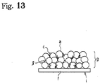
- a positive electrode h as an electrode structure o is manufactured by mixing a mixture e of a powdered electrode active substance a comprising LiCoO 2 , powdered electrically-conducting carbon b, a binder polymer c and a solvent d into a slurry, and applying it to a current-collecting member f and drying to form a compound film g, as shown in Fig. 13.
- the compound film g of Fig. 13 is a partial enlargement of the mixture e on the current-collecting member f.
- a negative electrode I as an electrode structure is manufactured by mixing the mixture e of the powdered electrode active substance a comprising powdered graphite, the binder polymer c and the solvent d into a slurry, applying it to the current-collecting member f, and drying to form the compound film g, as shown in Fig. 14.
- the electrode structure is designed such that the electrode structure o is sandwiched between two work rolls m, m as shown in Fig. 16; a roller for rolling is used to increase the filing density of the electrode active substance.
- rolling the electrode structure o is such that the electrode structure o inserted between the upper and lower work rolls m, m is pressed by being sandwiched between the upper and lower work rolls with a pressure force generated by a pressure device n, the weight of the upper work roll, and the weight of the housing p.
- a pressure device n the weight of the upper work roll
- the weight of the housing p the weight of the housing p.
- the upper and lower work rolls m, m may be designed thicker.
- the radial length pressing the electrode structure o viewing from the sectional direction of the rolls becomes longer, and there is no substantial change in the unit-area pressing force comparing to when the work rolls are in the previous thickness even if the work rolls are thicker.
- This invention is a roller processing/rolling an electrode structure in which a powdered electrode active substance is adhered to the current collecting member, comprising a pair of work rolls sandwiching and rolling the electrode structure, at least a pair of backup rolls generating a pressing force onto the respective work roll, a pressuring device pressing at least one of the backup roll toward the work roll side, and a drive unit rotating the work rolls.
- This invention still is a roller processing/rolling an electrode structure in which a powdered electrode active substance is adhered to the current collecting member, comprising a large diameter work roll and a small diameter other work roll having an electrode structure inbetween, a backup roll generating a pressing force onto the surface of the small diameter work roll, a pressuring device pressing the backup roll toward the small diameter work roll side, and a drive unit rotating the work roll.
- This invention still is a roller processing/rolling an electrode structure, wherein the roller comprises a work roll housing having an axle receive of the work roll inside and a housing having the respective roll axle inside, and a spacer is provided between the respective two housings.
- This invention still is an electrode structure for an electric part where ions move between the electrodes, wherein a powdered electrode active substance coated by an ion-conducting polymer is adhered to a current collecting member, and a roller processes/rolls the powdered electrode conductive substance on the current collecting member.
- This invention still further is an electrode structure for an electric part where ions move between the electrodes, wherein a powdered large surface material coated by an ion-conducting polymer is adhered to a current collecting member, and a roller processes/rolls the powdered electrode conductinve substance on the current collecting member.
- This invention yet further is an electrode structure mixing a powdered electrode active substance with a powdered electrode conducting substance.
- Electrodes wherein ions migrate between electrodes are those in which an ion-conducting substance is disposed between electrode structures functioning as electrodes, and ions migrate within the ion-conducting substance so that a current flows between the electrodes, e.g., primary cells, secondary cells, and an electric double layer capacitor.
- Batteries are characterized in that an ion-conducting substance disposed between the positive electrode structure and negative electrode structure and that an ion, including a proton or a positive hydrogen ion, migrates between electrodes and is accumulated.
- An electric double layer capacitor is characterized in that an ion-conducting substance is disposed between a pair of electrode structures and an electric double layer is formed between a large surface material within the electrode structures and an electrolyte of the ion-conducting substance.
- Electrode structures are used as electrodes in these electrical components, and exchange electrical charges with ions or draw ions.
- Fig. 13 and Fig. 14 show conventional structures that the powdered electrode active substance a is simply combined with the binder polymer c to adhere to the current-collecting member whereas
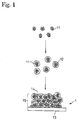
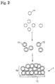
- Fig. 1 and Fig. 2 show the structure that the powdered electrode active substance 11 coated with the ion-conducting polymer 12 is adhered to the current-collecting member 13.
- they have a construction in which the powdered electrode active substance used for batteries or a powdered large surface material with a large surface area used for an electric double layer capacitor is made to adhere to a current-collecting member.
- Fig. 1 shows a process for manufacturing an electrode structure 1 wherein a powdered electrode substance, i.e., a powdered electrode active substance 11, comprising particles of a compound such as LiCoO 2 is coated with an ion-conducting polymer 12, and is made to adhere to a current-collecting member 13.
- Fig. 2 shows a process for manufacturing the electrode structure 1 wherein a powdered electrode substance, i.e., the powdered electrode active substance 11 having a form such as that of graphite or hard carbon is coated with the ion-conducting polymer 12, and is made to adhere to the current-collecting member 13.
- a powdered large surface material such as an activated carbon as the powdered electrode substance may be coated with the ion-conducting polymer and is adhered to the current-collecting member to form an electrode structure of the electric double layer capacitor.
- Fig. 1 shows the case where the electrical conductivity of the powdered electrode active substance 11 is low.
- the electrical conductivity in the powdered electrode active substance and between the powdered electrode active substance 11 and current-collecting member 13, is increased and the current-collecting efficiency improved by mixing with a powdered electrically-conducting substance 14.
- the powdered electrically-conducting substance 14 may or may not be coated with the ion-conducting polymer.
- Coating refers to a state of contact wherein ions can easily migrate between the ion-conducting polymer 12 and the powdered electrode substance, i.e., the powdered electrode active substance 11 over their entire surfaces or the powdered large surface material over their entire surfaces.
- the ion-conducting polymer 12 is coated on the surface of the powdered electrode active substance 11 or the powdered large surface material so that the latter is covered by the ion-conducting polymer 12.
- the powdered electrode active substance 11 becomes more active the finer the particles of which it is comprised, but its activity can be suppressed to give greater stability by coating with the ion-conducting polymer 12.
- the layer of the coated ion-conducting polymer 12 is thick, conductivity decreases and current-collecting efficiency is poorer, so it is preferably thin.
- powdered electrode active substance 11 the powdered electrically-conducting substance 14, or the powdered large surface material refers to a substance having a fine particle state. In some cases, it may refer to a state wherein a large number of substances having a fine particle state are agglomerated.
- the roller is activated to role the electrode structure 1 having an application layer 15 formed by applying the powdered electrode active substance 11 on the current-collecting member 13 in order to strengthen the adhesiveness between the powdered electrode active substance 11 and the current-collecting member 13 and to increase the density of the powdered electrode active substance 11.
- the rolled electrode structure may be a conventional structure or a structure coated with the ion-conducting polymer 12.
- the rolling device at least is able to rotate and press and has a structure as shown in Fig. 3(A).
- the tape electrode structure body 1 comprising the current collecting member 13 superposing an application layer 15 containing the powdered electrode active member as shown in Fig. 3(B), while under the control by a control device 5, is withdrawn from a unwinding roll 53, pre-treated by a preliminary treatment section 51, rolled by roller 4, post-treated by a subsequent treatment section 52, and winded on a winding roll 54.
- a tensile force and thickness of the tape electrode structure body 1 may be measured, and the electrode structure body 1 may be cleaned.
- a tensile force and thickness of the tape electrode structure body 1 may be measured, and the electrode structure body 1 may be cleaned.
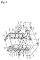
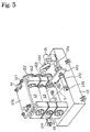
- roller 4 An example of roller 4 is explained with reference to Fig. 4 and Fig. 5.
- the roller 4 in Fig. 4 has a pair of work rolls 43, 43 and a pair of backup rolls 42, 42 pressurizing the work rolls 43, 43.
- diameter of the backup rolls 42, 42 may be designed to be larger than the small diameter work rolls 43, 43.
- the backup roll 42 is manufactured by adhering an extra-hard elastic material on the surface of an extra-hard material, which prevent from damaging the surface of the work roll 43 due to the contact with the work roll 43.
- This extra-hard elastic material may be denatured urethane or polyimide, and the hardness for example may be 80 or more at Rubber Code Shore D Scale of JIS but preferably between 90-98.
- the thickness of the extra-hard elastic material for example is between 100mm-30mm. Positioning the elastic material on the surface, oil and grease adversely affecting on the electrode structure body 1 may be omitted.
- the work roll 43 may be a small steel roll, being pushed by two large diameter rolls, thereby applying the large pressure on the electrode structure body 1 and applying a rolling force almost fills the void in the coating layer of the electrode structure body 1.
- the drive unit 45 such as a motor driving the rolls and the backup roll housing 42 having an axle receiving section of the lower backup roll 42 are positioned at the upper portion of the roller base 41.
- the pair of work roll housing 443, 443 of the pair of work rolls 43, 43 and a backup roll housing 442 of the upper backup roll are positioned at the upper portion of the lower backup roll housing 422.
- a roll axle 471 is rotatably installed at the respective axle receiving section 47.
- a gate-shape frame may be used instead of the diver 441.
- the respective roll housings 442, 443 is desirably positioned at both ends of the rolls 42, 43, where four divers 441 may be employed to stably be fixed.
- the unwinding core 411 and the winding core 412 are processed in the roller 4, and the electrode structure body 1 is withdrawn from the unwinding core 411 holding the electrode structure body 1, and the pair of work rolls 43, 43 are used to roll the electrode structure body 1, thereby winding by the winding core 412.
- the unwinding core 411 and the winding core 412 are installed on the frame 413 fixed on a stationary member such as a housing 442, and the motor 414 is activated to perform the drive control.
- a pressuring device 44 is fixed on the upper frame plate 415, and the upper backup roll housing 442 is pressed downward, so that the upper backup roll 42 presses the upper work roll 43 downward, thereby generating the pressure between the pair of work rolls 43, 43.
- the pressuring device presses both ends of the upper backup roll housing 442 and evenly presses the work roll 43 downward.
- the pressuring device 44 is position in the upper portion in Fig. 4 and Fig. 5, it may be positioned in the lower portion or positioned in either side if the rolls are arranged horizontally.
- the driving unit 45 transmits the rotating force to a work roll driving gear 453 via a driving belt 451 and what not.
- the work roll driving gear 453 and a backup roll driving gear 452 may be installed on the respective roll axle 471 of the rolls for the respective roll to rotate simultaneously or a main roll is directly driven while the remaining rolls may be dependently driven by a motor but simultaneously with the rotation of the main roll.
- the adjustment plate 46 may be a spring and a spacer, which maintains clearances among four rolls when a pressuring device such as a hydraulic cylinder is extended.
- the adjustment plate positioned between the work rolls 43, 43 adjust a gap appropriately so that the work rolls 43, 43 may not contact each other.
- the spring pushes the housings 442, 443 and rolls 42, 43 evenly with gaps when the pressuring device such as a cylinder moves backward.
- the pair of work rolls 43, 43, one roll is pressed by the large backup roll 42, and the other backup roll 42 is omitted at the large diameter work roll, thereby reducing the number of rolls required to be three which downsizes the roller 4.
- a pair of work rolls 43, 43 are divided into a large diameter roll and a small diameter roll.
- the small diameter work roll 43 is pressed by the large backup roll 42, and the other work roll 43 for the large diameter work roll 43 may be omitted.
- the pressuring device 44 pushes the backup roll 42 down from the above, and the electrode structure 1 inserted between the upper work roll 43 and the lower work roll 43 is rolled/processed due to the operation of the pressuring device 44.
- the diameter of the backup roll is set to be about 300mm while the diameter of the work roll is to be about 150mm, unit-area maximum pressure rotating the electrode structure 1 becomes twice or 2.5 times larger than the pressure in the traditional device, which improves cell effectiveness. Therefore, a finer work roll 43 comparing to the conventional work roll may be utilized and at the same time there is no difference due to a roll bent (bending of the work roll 43, 43), thereby maintaining the uniform gap.
- the gap between the work rolls 43, 43 may be adjusted so that the entire width is to be about 80 ⁇ for example by adjusting the adjustment plate 46 of the lower work roll 43. Then, when the electrode structure 1 is rolled by the work roll 43, the electrode structure 1 is inserted as the thickness of the adjustment plates 46, 46 of the upper work roll and the lower work roll may be adjusted making an adjustment for the work roll bending in order to uniform the thickness of the entire width of the electrode structure 1.
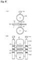
- the backup roll 42 may be designed to be a drum-shape (a roll with a clausing treatment) as shown in Fig. 6(B).
- Fig. 7 uses three work rolls, wherein the lower work roll has a larger diameter and is hard to be bent; the upper work roll has a smaller diameter so as to apply higher unit-area pressure on the electrode structure 1; pushing back by the backup roll 42 adjusts the amount of bending; and a uniform large pressure may be applied to the electrode structure 1.
- the adjustment of the thickness of the electrode 1 and the adjustment of the spacer may be facilitated.
- the thickness of the electrode structure 1 prior to the rolling is set to be 150 ⁇ and the gap of the work roll while rolling is to be 80 ⁇ , it was acknowledged that the thickness of the electrode structure after rolling regains and becomes desirable 100 ⁇ .
- the powdered electrode active substance may be a material which permits insertion and separation of ions, or a ⁇ -conjugated electrically-conducting polymer material.
- Electrode active material used as the positive electrode in a non-aqueous electrolytic battery there is no particular limitation on the electrode active material used as the positive electrode in a non-aqueous electrolytic battery, but in the case of a rechargeable secondary cell, a chalcogen compound permitting insertion and separation of lithium ions or a complex chalcogen compound containing lithium may for example be used.
- Examples of chalcogen compounds are FeS 2 , TiS 2 , MoS 2 , V 2 O 5 , V 6 O 13 and MnO 2 .
- Examples of chalcogen compounds containing lithium are LiCoO 2 , lithium complexes represented by LixNiyM 1 -yO 2 (where M is at least one metal element chosen from transition metals or Al, but preferably at least one metal element chosen from Co, Mn, Ti, Cr, V and Al, and 0.05 ⁇ x ⁇ 1.10, 0.5 ⁇ y ⁇ 1.0), LiNiO 2 , LiMnO 2 and LiMn 2 O 4 .
- These compounds may be obtained from the oxides, salts or hydroxides of lithium, cobalt, nickel or manganese as starting materials, mixing the starting materials depending on the composition, and firing in an oxygen atmosphere at a temperature in the range of 600 °C-1000 °C.
- the electrode active substance used as the negative electrode in a non-aqueous electrolyte battery there is no particular limitation on the electrode active substance used as the negative electrode in a non-aqueous electrolyte battery, but a material permitting insertion and separation of lithium ions may be used such as lithium metal, lithium alloy (alloys of lithium and aluminum, lead and indium, etc.), and carbon materials.
- ⁇ -conjugated conducting polymer materials are polyacetylenes, polyanilines, polypyrroles, polythiophenes, poly- ⁇ (para)-phenylenes, polycarbazoles, polyacenes and sulfur polymers.
- a large battery capacity can be obtained by using lithium metal for the negative electrode.
- an excellent cycle life can be obtained by using carbon materials which permit insertion and separation of lithium as the negative electrode.
- carbon materials which permit insertion and separation of lithium as the negative electrode.
- the carbon material examples being pyrolytic carbon, cokes (pitch coke, needle coke or petroleum coke), graphites, glass carbons, organic polymer compound firing products (products obtained by firing and carbonizing phenolic resins and furan resins at a suitable temperature), carbon fiber and active carbon.
- a powdered electrode substance with a large surface area is a powdered large surface material that may draw many ions on that surface.
- a preferable powdered large surface material is a carbon material with a specific surface area of 500m 2 /g or more, preferably 1000m 2 /g or more, and more preferably most preferably 1500m 2 /g-3000m 2 /g and an average particle diameter of 30 ⁇ m or less, preferably 5-30 ⁇ m.
- the specific surface area and the average particle diameter outside the above-ranges cause a large electrostatic capacity and make it difficult to obtain an electric double layer capacitor with a lower resistance.
- a preferable powdered large surface material especially is an activated carbon resulting from activating the carbon material such as by a steam activating treatment and a fused KOH activating treatment.
- the activated carbon for example may be palm shell activated carbon, a phenol activated carbon, a petroleum coke type activated carbon, mesofusepitch carbon, and polyacenes.
- One of the above activated carbon types or combination of two ore more activated carbon types may be employed.
- Phenol activated carbon, a petroleum coke type activated carbon, and a polyacenes are preferable since they provide a larger electrostatic capacity.
- the powdered electrically-conducting substance increases the electrical conductivity of the electrode structure, there being no particular limitation thereon, but metal powders and carbon powder may be used.
- carbon powder pyrolytic carbon such as carbon black and its graphitization products, artificial and natural scaly graphite powder, and carbon fiber and its graphitization products, are suitable. Mixtures of these carbon powders may also be used.
- the ion-conducting polymer is a polymer which can dissolve at least the lithium salts described hereafter at a concentration of at least 0.1M (moles/l), the polymer containing the lithium salt at a concentration of at least 0.1M having an electrical conductivity of 10 -8 S (siemens)/cm at room temperature. It is to be particularly preferred that the ion-conducting polymer dissolves at least lithium salts to a concentration of 0.8M-1.5M, the resulting polymer solution having an electrical conductivity of 10 -3 S/cm - 10 -5 S/cm at room temperature.
- the lithium salt is at least one type of lithium salt having ClO 4 - , CF 3 SO 3 - , BF 4 - , PF 6 - , AsF 6 - , SbF 6 - , CF 3 CO 2 - or (CF 3 SO 2 ) 2 N - as anion.
- the ion-conducting polymer raw material is a substance which produces the ion-conducting polymer by cross-linking, etc., when energy is supplied externally.
- the energy may be heat, ultraviolet light, light or electron radiation.
- the current-collecting member should be a substance which easily passes electricity. Its shape and material are selected according to the electrical components involved, and as an example, it can be formed by fashioning an electrically-conducting substance such as aluminum or copper into a plate, foil or mesh.
- one surface or both surfaces are used according to the structure of the electrical components, and the powdered electrode active substance is made to adhere to one surface or both surfaces.
- the secondary cell comprises the ion-conducting substance disposed between two types of the electrode structures 1.
- the secondary cell is formed by introducing a liquid such as the electrolyte 14 between an electrode structure 101 of the positive electrode and an electrode structure 102 of the negative electrode, and disposing a separator 15 between them as shown for example in Fig. 8(A).
- a solid electrolyte substance such as an ion-conducting polymer 16 between the electrode structure 101 of the positive electrode and the electrode structure 102 of the negative electrode as shown in Fig. 8(B).
- the electric double layer capacitor has a construction in which the powdered large surface material is used to form a pair of electrode structures and an electrolyte substance is disposed between the pair of electrode structures.
- the powdered electrode active substance is used as the powdered electrode substance, to manufacture the electrode structure, an extremely thin ion-conducting polymer or ion-conducting polymer raw material is coated on the surface of the powdered electrode active substance 11.
- a solvent is added to liquefy the mixture into a paste which is applied to the current-collecting member, and dried to evaporate the solvent.
- the solvent can be added from the beginning to make a paste when the ion-conducting polymer or ion-conducting polymer raw material is coated.
- the powdered large surface material is used as the powdered electrode substance, the same process applied with the powdered electrode active substance may be employed to manufacture the electrode structure.
- a minute amount of the ion-conducting polymer or ion-conducting polymer raw material is used, the particle surfaces of the powdered electrode active substance are coated with the ion-conducting polymer, no voids are formed, and gaps in the powdered substance are reduced.
- the ion-conducting polymer or ion-conducting polymer raw material and the powdered electrode active substance are press-slid together to obtain a press-slid product.
- Press-sliding is the action of sliding while pressing mixtures 10 of the ion-conducting polymer 12 or the raw material of the ion-conducting polymer 12 and the powdered substance 11 together. An external force is applied to the mixtures so that they cohere to each other and the particles rotate, and this process is performed repeatedly to obtain a press-sliding product.
- the press-sliding mixer is shown, for example, in Fig. 4.
- the mixture 10 of the ion-conducting polymer 12 or its raw material with the powdered substance 11, or the mixture 10 comprising this mixture and a solvent or the like, is introduced into a container 21, and the main blade 22 is rotated. There is a gap between a base 211 of the container 21 and a bottom surface of the main blade 22.
- part of the mixture 10 enters the space between the base 211 of the container and the main blade 22, is subjected to press-sliding, and is kneaded. This process is repeated so that the ion-conducting polymer 12 or its raw material coats the powdered substance 11.
- a press-sliding mixer 2 may if necessary be provided with a dispersion blade 23 in the container 21.
- the dispersion blade 23 is rotated at high speed to disperse the press-slid mixture 10.
- the container 21 is provided for holding the mixture 10 which is press-slid and stirred.
- the bottom surface of the container 21 may be such as to permit press-sliding of the mixture 10, and may be slanting as in Fig. 4 or flat as in Fig. 5.
- the center part may be situated in a low position, and have a slope rising towards the circumference.
- the bottom 211 may be formed in the shape of, for example, a grinding mortar, and the angle of the bottom part 2111 may for example be 120 degrees.
- the bottom 211 of the container is wear-resistant, and is formed by thermal spraying with tungsten or carbide using SUS. Plural bottom parts 2111 of this type may also be formed on the bottom surface.
- the main blade 22 functions together with the bottom surface of the container 21, serving to press-slide and stir the mixture.
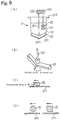
- a shaft is attached in a position corresponding to the bottom part 2111 of the container 21 as shown for example in Fig. 9(B), and it curves upwards along the bottom of the container from the bottom part 2111.
- the main blade 22 may comprise two blades attached from the center part as shown in Fig. 9(B), or it may comprise a larger number of blades, e.g. 10 or more, depending on the amount and type of mixture.
- the rotation speed of the main blade i.e., the number of rotations, is set low, for example to 120 rpm or less, when press-sliding is performed.
- the gap between the bottom surface of the container 21 and the base surface of the main blade 22 is set as narrow as is necessary for press-sliding the mixture, for example 15 mm or less.
- the surface in the motion direction (press-sliding direction) of the main blade 22 is formed so that a pressing angle ⁇ relative to the bottom surface of the container 21 is an acute angle.
- a pressing angle ⁇ relative to the bottom surface of the container 21 is an acute angle.
- the cross-section of the main blade 22 is a reverse trapezoid as shown in Fig. 9(C)
- the pressing angle is from 3 degrees to 70 degrees.
- the cross-section of the main blade 22 may also be circular or have a rounded comer as shown in Fig. 9(D).
- the material of the main blade has wear-resistant properties, and is formed for example by thermal spraying with tungsten or carbide using SUS.
- the mixture 10 can be collected around the main shaft 221 by rotating the main shaft 221 in the reverse direction.
- the dispersion blade 23 is intended to disperse the mixture 10 which has been press-slid by the main blade 22.
- the dispersion blade 23 is disposed in a position at which the mixture 10 can be dispersed, and it rotates at a high speed such as 1000-4000 rpm. Due to this high speed rotation, the ion-conducting polymer 12 or its raw material coated on the particle surfaces of the powdered substance 11 uniformly disperses through the whole of the powdered substance.
- the mixture adheres on the area surrounding the main shaft 221 of the main blade 22 when in firm mixing or low clay dispersion and tends to be ununiformed mixing.
- the dispersion blade 23 is positioned on the main shaft 221 of the main blade 22, rotating the same from the dry mixing stage to prevent the adhesion on the area surrounding the main shaft 221.
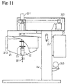
- the press-sliding mixer is supported on a supporting platform 24, the container 21 being raised by a handle 241, and is controlled by a control panel 25.
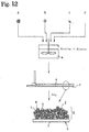
- the powdered substance 11 (containing an additive) is measured out, and introduced from a powdered substance input port 34.
- a measuring hopper or the like is installed above the powdered substance input port 34 for storage and measurement, and a valve 341 of the powdered substance input port is automatically opened by an input command.
- a discharge port 32 fitted with an aspiration filter 322 is opened alone so that only air is discharged.
- a valve 331 of an input port 33 for the ion-conducting polymer or its raw material is opened, and the polymer or its raw material is measured out manually or automatically and introduced into the container in the same way as the powdered substance.
- the input valves 331, 341 are closed. Further, if warm water at 30 °C is recirculated through a jacket 213 of the container to promote wetting of the powdered substance and the ion-conducting polymer or its raw material, the wetting efficiency can be improved. However, when a penetration-assisting solvent is used, processing is performed at ordinary temperature.
- the main motor 222 is rotated at a low speed of about 10 rpm, the mixture 10 of the ion-conducting polymer or its raw material and the powdered substance is press-slid between the bottom surface of the container 21 and the main blade 22, and the ion-conducting polymer or its raw material gradually begins to penetrate the powdered substance.
- the press-slid mixture 10 rises up the container at the tip of the main blade 22, the mixture 10 falls down from above the center part of the container, and a turning over action takes place in the container over its entire circumference. This is repeated regularly so that the whole mixture is uniformly press-slid.
- the rotation speed of the main shaft 221 is automatically or manually increased to 60 rpm, and when wetting of the mixture 10 has reached effectively half of the surface area, a vacuum pump 353 of a degassing port 35 is operated, a degassing valve 351 is opened, and degassing is performed via a filter 352 for about 1 hour.
- the main blade 22 press-slides the mixture 10 while degassing is performed, so wetting and penetration dispersion of the ion-conducting polymer or its raw material in the powdered substance is promoted.
- the dispersion blade When penetration degassing has reached about 70% after degassing for approximately 1 hour, the dispersion blade is rotated at 2800 rpm to promote dispersion.
- the press-slid substance which has been made into a paste is thinly applied to the surface of the current-collecting member. After application, the solvent evaporates and dries to obtain the electrode structure.
- the device which applies the press-slid substance to the current-collecting member may be a doctor knife applicator.
- the applied electrode structure is applied to the tape current collecting member as shown so that the application layer at the respective electrode is isolated in Fig. 3(B).
- the electrode structure 1 s is set between the work rolls 43 and 43, and stall tension (tension at the stand by state and 20-30% tension at driving) is applied to the electrode structure 1 between the unwinding rollers 53 and 54.
- stall tension tension at the stand by state and 20-30% tension at driving
- the entire line is driven in extremely low speed.
- the upper backup roll housing 442 and the upper backup roll 42 begin to move downward due to the operation of the pressuring device.
- the upper backup roll 42 and the upper work roll 43 make a line contact, and the upper work roll 43 together with the upper backup roll 42 rotate and move downward.
- the upper work roll 43 contacts the upper surface of the electrode structure 1; three rolls contact and roll; if the rolls move downward further by pressing the spring, the lower work roll 42 comes to contact with the surface of the lower backup roll 42.
- four rolls synchronize and begin to make low r.p.m. operation.
- the pressuring device 44 such as a hydraulic cylinder further pressurize the upper backup roll housing 442 with the predetermined pressure, and roll surfaces of four rolls are evenly pressurized.
- the application layer 15 and the current collecting member 13 are compressed together to be compressed and expanded in the cross direction to be deformed.
- a layer without the application layer 15 is not compressed, and therefore no compression occurs. Accordingly, the boundary section between the application layer 15 and the layer without the application layer 15 brake and the strength is decreased. Limit of this tensile force is considered to be about twice as the tensile force by the unwinding roller 54.
- the pressing force on the work rolls 43, 43 is increased, and the best rolling with high compressibility prior to the breakage of the electrode structure 1.
- the conventional roller is comprised of two work roles without a backup roll, and the pressing force may not be increased due to the distortion of the work roll.
- the roller 4 in this invention is capable of rolling the electrode structure 1 until it breaks and to obtain the electrode structure 1 with high compressibility before the breakage, thereby obtaining high electrode density and low electrode impedance.
- the electrode density increase means an increase in the area of contact between the powdered electrode active substances in the electrode structure and between the powdered electrode active substance and the powdered electrode conducting substance in the electrode structure.
- impedance of the electrode decreases.
- the area of contact between the current collecting member and the powdered electrode active substance and the powdered electrode conducting substance may be set larger. Impedance of the electrode itself decreases to become a desirable electrode.
- the electrode density increases, and the amount relative to unit-area surface of the powdered electrode active substance and the powdered electrode conducting substance in the electrode structure 1 increases. As a result, if the electrode structure 1 is used for a cell, the area-unit energy density increases, thereby the entire cell becomes smaller.
- the press-slid substance was paste-like.
- 0.254 weight parts of polymeric MDI, MR-200 (NPU Co.) was added to the press-slid substance, and the mixture stirred for 5 minutes in the press-sliding mixer.
- the press-slid substance was removed, transferred to aluminum foil of thickness 20 ⁇ m, and spread by a doctor knife applicator of 100 ⁇ m gap.
- the resulting product was left at room temperature for 15 minutes, and then heated at 80°C for 1 hour.
- the electrode with a single applied surface obtained is turned upside down to be fixed on a flat surface and is spread by a doctor knife applicator of 100 ⁇ m gap similarly.
- the resulting product was left at room temperature for 15 minutes, and then heated at 80°C for 1 hour.
- the electrode obtained is the electrode layer applied on both side of aluminum foil of thickness 20 ⁇ m gap, and the entire thickness was 170 ⁇ m.
- This electrode of the invention is rolled by three rollers at room temperature. The thickness of the electrode after rolling was 120 ⁇ m gap.
- LiCoO 2 of average particle size 5 ⁇ m which is a powdered electrode active substance 9.1 weight parts of LiCoO 2 of average particle size 5 ⁇ m which is a powdered electrode active substance, 0.341 weight parts of an ion-conducting polymer raw material (A1) and 3.0 weight parts of acetonitrile were introduced into a press-sliding mixer (capacity 300cc), and the mixture press-slid for 7 hours. The press-slid substance was paste-like. Next, 0.159 weight parts of polymeric MDI, MR-200 (NPU Co.) was added, and the mixture press-slid for 5 minutes. The press-slid substance was removed, transferred to aluminum foil of thickness 20 ⁇ m, and spread by a doctor knife applicator of 100 ⁇ m gap.
- the resulting product was left at room temperature for 15 minutes, and heated at 80°C for 1 hour.
- the thickness of the electrode obtained was 80 ⁇ m.
- the electrode obtained is the electrode layer applied on both side of aluminum foil of thickness 20 ⁇ m gap, and the entire thickness was 170 ⁇ m.
- This electrode of the invention is rolled by three rollers at room temperature. The thickness of the electrode after rolling was 120 ⁇ m gap.
- the press-slid substance was paste-like.
- a solution of 0.01 weight parts of 2,2'-azobis (2,4-dimethylvaleronitrile) and 0.5 weight parts of a (1/1) vol liquid electrolyte of ethylene carbonate (EC)/diethylene carbonate (DEC) was added to the press-slid substance, and the mixture further press-slid for 5 minutes.
- the press-slid substance was removed, transferred to aluminum foil of thickness 20 ⁇ m, and spread by a doctor knife applicator of 100 ⁇ m gap.
- the resulting product was left at room temperature for 15 minutes, and heated at 80 °C for 3 hours.
- the electrode with a single applied surface obtained is turned upside down to be fixed on a flat surface and is spread by a doctor knife applicator of 100 ⁇ m gap similarly.
- the resulting product was left at room temperature for 15 minutes, and then heated at 80°C for 1 hour.
- the electrode obtained is the electrode layer applied on both side of aluminum foil of thickness 20 ⁇ m gap, and the entire thickness was 170 ⁇ m.
- This electrode of the invention is rolled by three rollers at room temperature. The thickness of the electrode after rolling was 120 ⁇ m gap.
- the resulting product was left at room temperature for 15 minutes, and heated at 80°C for 1 hour.
- the electrode with a single applied surface obtained is turned upside down to be fixed on a flat surface and is spread by a doctor knife applicator of 100 ⁇ m gap similarly.
- the resulting product was left at room temperature for 15 minutes, and then heated at 80°C for 1 hour.
- the electrode obtained is the electrode layer applied on both side of aluminum foil of thickness 20 ⁇ m gap, and the entire thickness was 170 ⁇ m.
- This electrode of the invention is rolled by three rollers at room temperature. The thickness of the electrode after rolling was 120 ⁇ m gap.
- the press-slid substance was removed, transferred to copper foil of thickness 20 ⁇ m, and spread by a doctor knife applicator of 100 ⁇ m gap.
- the resulting product was left at room temperature for 15 minutes, and heated at 80°C for 3 hours.
- the electrode with a single applied surface obtained is turned upside down to be fixed on a flat surface and is spread by a doctor knife applicator of 100 ⁇ m gap similarly.
- the resulting product was left at room temperature for 15 minutes, and then heated at 80°C for 1 hour.
- the electrode obtained is the electrode layer applied on both side of aluminum foil of thickness 20 ⁇ m gap, and the entire thickness was 170 ⁇ m.
- This electrode of the invention is rolled by three rollers at room temperature. The thickness of the electrode after rolling was 120 ⁇ m gap.
- the resulting product was left at room temperature for 15 minutes, and heated at 80°C for 3 hours.
- the electrode with a single applied surface obtained is turned upside down to be fixed on a flat surface and is spread by a doctor knife applicator of 100 ⁇ m gap similarly.
- the resulting product was left at room temperature for 15 minutes, and then heated at 80°C for 1 hour.
- the electrode obtained is the electrode layer applied on both side of aluminum foil of thickness 20 ⁇ m gap, and the entire thickness was 170 ⁇ m.
- This electrode of the invention is rolled by three rollers at room temperature. The thickness of the electrode after rolling was 120 ⁇ m gap.
- the electrode with a single applied surface obtained is turned upside down to be fixed on a flat surface and is spread by a doctor knife applicator of 100 ⁇ m gap similarly.
- the resulting product was left at room temperature for 15 minutes, and then heated at 80°C for 1 hour.
- the electrode obtained is the electrode layer applied on both side of aluminum foil of thickness 20 ⁇ m gap, and the entire thickness was 170 ⁇ m.
- This electrode of the invention is rolled by three rollers at room temperature. The thickness of the electrode after rolling was 120 ⁇ m gap.
- the resulting product was left at room temperature for 15 minutes, and heated at 80°C for 3 hours.
- the electrode with a single applied surface obtained is turned upside down to be fixed on a flat surface and is spread by a doctor knife applicator of 100 ⁇ m gap similarly.
- the resulting product was left at room temperature for 15 minutes, and then heated at 80°C for 1 hour.
- the electrode obtained is the electrode layer applied on both side of aluminum foil of thickness 20 ⁇ m gap, and the entire thickness was 170 ⁇ m.
- This electrode of the invention is rolled by three rollers at room temperature. The thickness of the electrode after rolling was 140 ⁇ m gap.
- the electrode with a single applied surface obtained is turned upside down to be fixed on a flat surface and is spread by a doctor knife applicator of 100 ⁇ m gap similarly.
- the resulting product was left at room temperature for 15 minutes, and then heated at 80°C for 1 hour.
- the electrode obtained is the electrode layer applied on both side of aluminum foil of thickness 20 ⁇ m gap, and the entire thickness was 170 ⁇ m.
- This electrode of the invention is rolled by three rollers at room temperature. The thickness of the electrode after rolling was 140 ⁇ m gap.
- a test lithium ion secondary cell was manufactured using the positive electrode structures manufactured in the examples and comparative examples.
- the positive electrode and negative electrode were both cut out to have an electrode surface area of 4cm 2 .
- Completely solid polymer (all polymer), polymer gel electrolyte (polymer gel), liquid electrolyte (liquid) and a separator were sandwiched between the positive electrode and negative electrode to manufacture the test cell.
- the concentration of lithium salt (supporting electrolyte salt) in the respective electrolytes was arranged to be 1 M.
- This cell was charged at 0.3mA per 1cm 2 of electrolyte surface area to 4.1V, and after allowing to stand for 15 minutes, it was discharged at 0.3mA/cm 2 to 2.7V. Combinations for which two of these charging/discharging cycles were successfully performed, were considered to be combinations for which charging/discharging is possible, and are shown in Table 3.
- Table 4 shows the contents of the electrolytes listed in Table 3.
- test cells using the positive electrode and negative electrode of this invention could be successfully charged and discharged.
- test cells using the electrodes of the comparative examples and a solid or gel electrolyte could not be charged/discharged, although test cells using liquid electrolytes could be charged/discharged.
- Japanese Patent Application Laid-Open No. 8-225626 100 ⁇ m AP2 All polymer Cyanoethylated/dihydroxypropylated cellulose and methacryl polymer 3D cross-linked structure (e.g. Japanese Patent Application Laid-Open No. 8-225626) 100 ⁇ m AP3 All polymer High viscosity polyurethane electrolyte (e.g. Japanese Patent Application No. 11-78085) 100 ⁇ m AP4 All polymer Cyanoethylated/dihydroxypropylated polyvinyl alcohol (e.g. Japanese Patent Application No.
Landscapes
- Engineering & Computer Science (AREA)
- Power Engineering (AREA)
- Chemical & Material Sciences (AREA)
- Manufacturing & Machinery (AREA)
- Chemical Kinetics & Catalysis (AREA)
- General Chemical & Material Sciences (AREA)
- Electrochemistry (AREA)
- Microelectronics & Electronic Packaging (AREA)
- Mechanical Engineering (AREA)
- Composite Materials (AREA)
- Materials Engineering (AREA)
- Battery Electrode And Active Subsutance (AREA)
- Press Drives And Press Lines (AREA)
Abstract
It is an object of this invention to provide a roller which is effective and
suitable for rolling the electrode structure 1 coated with an elastic material on its
surface and is to provide a processed electrode structure, the roller comprises a
pair of work rolls 43, 43 sandwiching the electrode structure for rolling, at least a
pair of backup rolls 42, 42 pressurizing the respective work roll, a pressuring
device 44 pressurizing at least one of the backup rolls toward the work roll side,
and a drive unit 45 rotating the work roll 43.
Description
This invention relates to a coating of an ion-conducting polymer on an
electrode structure for an electrical component such as a primary and secondary
cell, a capacitor, and an electric double layer capacitor.
In the prior art, in a lithium ion battery, a positive electrode h as an electrode
structure o is manufactured by mixing a mixture e of a powdered electrode active
substance a comprising LiCoO2, powdered electrically-conducting carbon b, a
binder polymer c and a solvent d into a slurry, and applying it to a current-collecting
member f and drying to form a compound film g, as shown in Fig. 13.
The compound film g of Fig. 13 is a partial enlargement of the mixture e on the
current-collecting member f.
A negative electrode I as an electrode structure is manufactured by mixing
the mixture e of the powdered electrode active substance a comprising powdered
graphite, the binder polymer c and the solvent d into a slurry, applying it to the
current-collecting member f, and drying to form the compound film g, as shown in
Fig. 14.
The electrode structure is designed such that the electrode structure o is
sandwiched between two work rolls m, m as shown in Fig. 16; a roller for rolling
is used to increase the filing density of the electrode active substance. However,
in rolling the electrode structure o is such that the electrode structure o inserted
between the upper and lower work rolls m, m is pressed by being sandwiched
between the upper and lower work rolls with a pressure force generated by a
pressure device n, the weight of the upper work roll, and the weight of the
housing p. In that case, although there is no issue to be resolved if such force is
lower, if the force is higher both upper and lower work rolls becomes distorted.
In order to withstand against the distortion, the upper and lower work rolls m, m
may be designed thicker. Yet, the radial length pressing the electrode structure
o viewing from the sectional direction of the rolls becomes longer, and there is no
substantial change in the unit-area pressing force comparing to when the work
rolls are in the previous thickness even if the work rolls are thicker.
As shown in Fig. 15, since the conventional lithium ion secondary cell itself
has a liquid electrolyte j filled between the positive electrode h and the negative
electrode I, appropriate void I is to be remained in the electrode active substance
layer (mixture film) flowing the electrolyte j around the electrode active substance,
thereby practically functioning as a cell.
However, if a solid electrolyte instead of a liquid electrolyte is used, the solid
electrolyte just like the liquid electrolyte cannot flow around the electrode active
substance. Therefore, no sufficient current density is attained, which makes it
impossible to practically function as a cell.
It is an object of this invention to provide a roller suitable for rolling the
electrode structure.
It is another object of this invention to provide an effective electrode structure.
(This invention relates to the following the roller.)
This invention is a roller processing/rolling an electrode structure in which a
powdered electrode active substance is adhered to the current collecting member,
comprising a pair of work rolls sandwiching and rolling the electrode structure, at
least a pair of backup rolls generating a pressing force onto the respective work
roll, a pressuring device pressing at least one of the backup roll toward the work
roll side, and a drive unit rotating the work rolls.
This invention still is a roller processing/rolling an electrode structure in
which a powdered electrode active substance is adhered to the current collecting
member, comprising a large diameter work roll and a small diameter other work
roll having an electrode structure inbetween, a backup roll generating a pressing
force onto the surface of the small diameter work roll, a pressuring device
pressing the backup roll toward the small diameter work roll side, and a drive unit
rotating the work roll.
This invention still is a roller processing/rolling an electrode structure,
wherein the roller comprises a work roll housing having an axle receive of the
work roll inside and a housing having the respective roll axle inside, and a spacer
is provided between the respective two housings.
This invention still is an electrode structure for an electric part where ions
move between the electrodes, wherein a powdered electrode active substance
coated by an ion-conducting polymer is adhered to a current collecting member,
and a roller processes/rolls the powdered electrode conductive substance on the
current collecting member.
This invention still further is an electrode structure for an electric part where
ions move between the electrodes, wherein a powdered large surface material
coated by an ion-conducting polymer is adhered to a current collecting member,
and a roller processes/rolls the powdered electrode conductinve substance on
the current collecting member.
This invention yet further is an electrode structure mixing a powdered
electrode active substance with a powdered electrode conducting substance.
This invention will now be described in more detail referring to the drawings.
Electrical components wherein ions migrate between electrodes are those in
which an ion-conducting substance is disposed between electrode structures
functioning as electrodes, and ions migrate within the ion-conducting substance
so that a current flows between the electrodes, e.g., primary cells, secondary
cells, and an electric double layer capacitor.
Batteries are characterized in that an ion-conducting substance disposed
between the positive electrode structure and negative electrode structure and
that an ion, including a proton or a positive hydrogen ion, migrates between
electrodes and is accumulated. An electric double layer capacitor is
characterized in that an ion-conducting substance is disposed between a pair of
electrode structures and an electric double layer is formed between a large
surface material within the electrode structures and an electrolyte of the ion-conducting
substance.
Electrode structures are used as electrodes in these electrical components,
and exchange electrical charges with ions or draw ions. Fig. 13 and Fig. 14
show conventional structures that the powdered electrode active substance a is
simply combined with the binder polymer c to adhere to the current-collecting
member whereas Fig. 1 and Fig. 2 show the structure that the powdered
electrode active substance 11 coated with the ion-conducting polymer 12 is
adhered to the current-collecting member 13. For instance, they have a
construction in which the powdered electrode active substance used for batteries
or a powdered large surface material with a large surface area used for an
electric double layer capacitor is made to adhere to a current-collecting member.
Fig. 1 shows a process for manufacturing an electrode structure 1 wherein a
powdered electrode substance, i.e., a powdered electrode active substance 11,
comprising particles of a compound such as LiCoO2 is coated with an ion-conducting
polymer 12, and is made to adhere to a current-collecting member 13.
Likewise, Fig. 2 shows a process for manufacturing the electrode structure 1
wherein a powdered electrode substance, i.e., the powdered electrode active
substance 11 having a form such as that of graphite or hard carbon is coated with
the ion-conducting polymer 12, and is made to adhere to the current-collecting
member 13. A powdered large surface material such as an activated carbon as
the powdered electrode substance may be coated with the ion-conducting
polymer and is adhered to the current-collecting member to form an electrode
structure of the electric double layer capacitor.
Fig. 1 shows the case where the electrical conductivity of the powdered
electrode active substance 11 is low. The electrical conductivity in the
powdered electrode active substance and between the powdered electrode
active substance 11 and current-collecting member 13, is increased and the
current-collecting efficiency improved by mixing with a powdered electrically-conducting
substance 14. The powdered electrically-conducting substance 14
may or may not be coated with the ion-conducting polymer.
"Coating" refers to a state of contact wherein ions can easily migrate
between the ion-conducting polymer 12 and the powdered electrode substance,
i.e., the powdered electrode active substance 11 over their entire surfaces or the
powdered large surface material over their entire surfaces. The ion-conducting
polymer 12 is coated on the surface of the powdered electrode active substance
11 or the powdered large surface material so that the latter is covered by the ion-conducting
polymer 12. The powdered electrode active substance 11 becomes
more active the finer the particles of which it is comprised, but its activity can be
suppressed to give greater stability by coating with the ion-conducting polymer
12.
If the layer of the coated ion-conducting polymer 12 is thick, conductivity
decreases and current-collecting efficiency is poorer, so it is preferably thin.
The term "powdered" as used in the powdered electrode active substance 11,
the powdered electrically-conducting substance 14, or the powdered large
surface material refers to a substance having a fine particle state. In some
cases, it may refer to a state wherein a large number of substances having a fine
particle state are agglomerated.
For the purpose of obtaining a desirable electrode structure 1, the roller is
activated to role the electrode structure 1 having an application layer 15 formed
by applying the powdered electrode active substance 11 on the current-collecting
member 13 in order to strengthen the adhesiveness between the powdered
electrode active substance 11 and the current-collecting member 13 and to
increase the density of the powdered electrode active substance 11. The rolled
electrode structure may be a conventional structure or a structure coated with the
ion-conducting polymer 12.
The rolling device at least is able to rotate and press and has a structure as
shown in Fig. 3(A). In this rolling device, the tape electrode structure body 1,
comprising the current collecting member 13 superposing an application layer 15
containing the powdered electrode active member as shown in Fig. 3(B), while
under the control by a control device 5, is withdrawn from a unwinding roll 53,
pre-treated by a preliminary treatment section 51, rolled by roller 4, post-treated
by a subsequent treatment section 52, and winded on a winding roll 54.
When in pre-treating, a tensile force and thickness of the tape electrode
structure body 1 may be measured, and the electrode structure body 1 may be
cleaned. Alternatively, when in post-treating, a tensile force and thickness of
the tape electrode structure body 1 may be measured, and the electrode
structure body 1 may be cleaned.
An example of roller 4 is explained with reference to Fig. 4 and Fig. 5. The
roller 4 in Fig. 4 has a pair of work rolls 43, 43 and a pair of backup rolls 42, 42
pressurizing the work rolls 43, 43. In order to generate higher pressure on the
work rolls 43, 43, diameter of the backup rolls 42, 42 may be designed to be
larger than the small diameter work rolls 43, 43. The backup roll 42 is
manufactured by adhering an extra-hard elastic material on the surface of an
extra-hard material, which prevent from damaging the surface of the work roll 43
due to the contact with the work roll 43. This extra-hard elastic material may be
denatured urethane or polyimide, and the hardness for example may be 80 or
more at Rubber Code Shore D Scale of JIS but preferably between 90-98. The
thickness of the extra-hard elastic material for example is between 100mm-30mm.
Positioning the elastic material on the surface, oil and grease adversely
affecting on the electrode structure body 1 may be omitted. The work roll 43
may be a small steel roll, being pushed by two large diameter rolls, thereby
applying the large pressure on the electrode structure body 1 and applying a
rolling force almost fills the void in the coating layer of the electrode structure
body 1.
The drive unit 45,such as a motor driving the rolls and the backup roll
housing 42 having an axle receiving section of the lower backup roll 42 are
positioned at the upper portion of the roller base 41. The pair of work roll
housing 443, 443 of the pair of work rolls 43, 43 and a backup roll housing 442 of
the upper backup roll are positioned at the upper portion of the lower backup roll
housing 422. A roll axle 471 is rotatably installed at the respective axle
receiving section 47.
The respective backup roll housing 442 and the respective work roll housing
443, each has a hole through which a diver 441 is penetrated, and the respective
work roll housing 443 and the respective backup roll housing 442, each is placed
between the roller base 41 and the upper frame plate 415 to penetrate the diver
441 in order to prevent the deviation of the positions of the rolls 42, 43. A gate-shape
frame may be used instead of the diver 441. The respective roll housings
442, 443 is desirably positioned at both ends of the rolls 42, 43, where four divers
441 may be employed to stably be fixed.
As necessary, the unwinding core 411 and the winding core 412 are
processed in the roller 4, and the electrode structure body 1 is withdrawn from
the unwinding core 411 holding the electrode structure body 1, and the pair of
work rolls 43, 43 are used to roll the electrode structure body 1, thereby winding
by the winding core 412. In that case, the unwinding core 411 and the winding
core 412 are installed on the frame 413 fixed on a stationary member such as a
housing 442, and the motor 414 is activated to perform the drive control.
A pressuring device 44 is fixed on the upper frame plate 415, and the upper
backup roll housing 442 is pressed downward, so that the upper backup roll 42
presses the upper work roll 43 downward, thereby generating the pressure
between the pair of work rolls 43, 43. The pressuring device presses both ends
of the upper backup roll housing 442 and evenly presses the work roll 43
downward. Although the pressuring device 44 is position in the upper portion in
Fig. 4 and Fig. 5, it may be positioned in the lower portion or positioned in either
side if the rolls are arranged horizontally.
The driving unit 45 transmits the rotating force to a work roll driving gear 453
via a driving belt 451 and what not. As necessary, the work roll driving gear 453
and a backup roll driving gear 452 may be installed on the respective roll axle
471 of the rolls for the respective roll to rotate simultaneously or a main roll is
directly driven while the remaining rolls may be dependently driven by a motor
but simultaneously with the rotation of the main roll.
Placing an adjustment plate 46 between the respective roll housings
prevents a pressure failure between the respective rolls due to the deviation in
the preciseness of the pressure and the operation by the pressuring device 44,
which assures the preciseness of the thickness of the electrode structure body 1.
For example, the adjustment plate 46 may be a spring and a spacer, which
maintains clearances among four rolls when a pressuring device such as a
hydraulic cylinder is extended. The adjustment plate positioned between the
work rolls 43, 43 adjust a gap appropriately so that the work rolls 43, 43 may not
contact each other. The spring pushes the housings 442, 443 and rolls 42, 43
evenly with gaps when the pressuring device such as a cylinder moves
backward.
In the roller as shown in Fig. 5, the pair of work rolls 43, 43, one roll is
pressed by the large backup roll 42, and the other backup roll 42 is omitted at the
large diameter work roll, thereby reducing the number of rolls required to be three
which downsizes the roller 4.
In order to increase the pressing force, a pair of work rolls 43, 43 are divided
into a large diameter roll and a small diameter roll. The small diameter work roll
43 is pressed by the large backup roll 42, and the other work roll 43 for the large
diameter work roll 43 may be omitted.
As shown in Fig. 6, the pressuring device 44 pushes the backup roll 42 down
from the above, and the electrode structure 1 inserted between the upper work
roll 43 and the lower work roll 43 is rolled/processed due to the operation of the
pressuring device 44. If the diameter of the backup roll is set to be about
300mm while the diameter of the work roll is to be about 150mm, unit-area
maximum pressure rotating the electrode structure 1 becomes twice or 2.5 times
larger than the pressure in the traditional device, which improves cell
effectiveness. Therefore, a finer work roll 43 comparing to the conventional
work roll may be utilized and at the same time there is no difference due to a roll
bent (bending of the work roll 43, 43), thereby maintaining the uniform gap.
Therefore, the gap between the work rolls 43, 43 may be adjusted so that
the entire width is to be about 80µ for example by adjusting the adjustment
plate 46 of the lower work roll 43. Then, when the electrode structure 1 is rolled
by the work roll 43, the electrode structure 1 is inserted as the thickness of the
adjustment plates 46, 46 of the upper work roll and the lower work roll may be
adjusted making an adjustment for the work roll bending in order to uniform the
thickness of the entire width of the electrode structure 1. In this case, the
backup roll 42 may be designed to be a drum-shape (a roll with a clausing
treatment) as shown in Fig. 6(B).
Fig. 7 uses three work rolls, wherein the lower work roll has a larger
diameter and is hard to be bent; the upper work roll has a smaller diameter so as
to apply higher unit-area pressure on the electrode structure 1; pushing back by
the backup roll 42 adjusts the amount of bending; and a uniform large pressure
may be applied to the electrode structure 1. In addition, the adjustment of the
thickness of the electrode 1 and the adjustment of the spacer may be facilitated.
Under the above-condition, for example, the thickness of the electrode
structure 1 prior to the rolling is set to be 150 µ and the gap of the work roll while
rolling is to be 80 µ , it was acknowledged that the thickness of the electrode
structure after rolling regains and becomes desirable 100µ.
The powdered electrode active substance may be a material which permits
insertion and separation of ions, or a π-conjugated electrically-conducting
polymer material.
There is no particular limitation on the electrode active material used as the
positive electrode in a non-aqueous electrolytic battery, but in the case of a
rechargeable secondary cell, a chalcogen compound permitting insertion and
separation of lithium ions or a complex chalcogen compound containing lithium
may for example be used.
Examples of chalcogen compounds are FeS2, TiS2, MoS2, V2O5, V6O13 and
MnO2. Examples of chalcogen compounds containing lithium are LiCoO2,
lithium complexes represented by LixNiyM1-yO2 (where M is at least one metal
element chosen from transition metals or Al, but preferably at least one metal
element chosen from Co, Mn, Ti, Cr, V and Al, and 0.05≦x≦1.10, 0.5≦y≦1.0),
LiNiO2, LiMnO2 and LiMn2O4. These compounds may be obtained from the
oxides, salts or hydroxides of lithium, cobalt, nickel or manganese as starting
materials, mixing the starting materials depending on the composition, and firing
in an oxygen atmosphere at a temperature in the range of 600 °C-1000 °C.
There is no particular limitation on the electrode active substance used as
the negative electrode in a non-aqueous electrolyte battery, but a material
permitting insertion and separation of lithium ions may be used such as lithium
metal, lithium alloy (alloys of lithium and aluminum, lead and indium, etc.), and
carbon materials.
Examples of π-conjugated conducting polymer materials are
polyacetylenes, polyanilines, polypyrroles, polythiophenes, poly-ρ (para)-phenylenes,
polycarbazoles, polyacenes and sulfur polymers.
In particular, in non-aqueous electrolyte primary cells, a large battery
capacity can be obtained by using lithium metal for the negative electrode.
In non-aqueous electrolyte secondary cells, an excellent cycle life can be
obtained by using carbon materials which permit insertion and separation of
lithium as the negative electrode. There is no particular limitation on the carbon
material, examples being pyrolytic carbon, cokes (pitch coke, needle coke or
petroleum coke), graphites, glass carbons, organic polymer compound firing
products (products obtained by firing and carbonizing phenolic resins and furan
resins at a suitable temperature), carbon fiber and active carbon.
A powdered electrode substance with a large surface area is a powdered
large surface material that may draw many ions on that surface.
A preferable powdered large surface material is a carbon material with a
specific surface area of 500m2/g or more, preferably 1000m2/g or more, and
more preferably most preferably 1500m2/g-3000m2/g and an average particle
diameter of 30µm or less, preferably 5-30µm. The specific surface area and
the average particle diameter outside the above-ranges cause a large
electrostatic capacity and make it difficult to obtain an electric double layer
capacitor with a lower resistance.
A preferable powdered large surface material especially is an activated
carbon resulting from activating the carbon material such as by a steam
activating treatment and a fused KOH activating treatment. The activated
carbon for example may be palm shell activated carbon, a phenol activated
carbon, a petroleum coke type activated carbon, mesofusepitch carbon, and
polyacenes. One of the above activated carbon types or combination of two ore
more activated carbon types may be employed. Phenol activated carbon, a
petroleum coke type activated carbon, and a polyacenes are preferable since
they provide a larger electrostatic capacity.
The powdered electrically-conducting substance increases the electrical
conductivity of the electrode structure, there being no particular limitation thereon,
but metal powders and carbon powder may be used. As carbon powder,
pyrolytic carbon such as carbon black and its graphitization products, artificial
and natural scaly graphite powder, and carbon fiber and its graphitization
products, are suitable. Mixtures of these carbon powders may also be used.
The ion-conducting polymer is a polymer which can dissolve at least the
lithium salts described hereafter at a concentration of at least 0.1M (moles/l), the
polymer containing the lithium salt at a concentration of at least 0.1M having an
electrical conductivity of 10-8 S (siemens)/cm at room temperature. It is to be
particularly preferred that the ion-conducting polymer dissolves at least lithium
salts to a concentration of 0.8M-1.5M, the resulting polymer solution having an
electrical conductivity of 10-3 S/cm - 10-5 S/cm at room temperature.
The lithium salt is at least one type of lithium salt having ClO4 -, CF3SO3 -, BF4 -,
PF6 -, AsF6 -, SbF6 -, CF3CO2 - or (CF3SO2)2N- as anion.
The ion-conducting polymer raw material is a substance which produces the
ion-conducting polymer by cross-linking, etc., when energy is supplied externally.
The energy may be heat, ultraviolet light, light or electron radiation.
The current-collecting member should be a substance which easily passes
electricity. Its shape and material are selected according to the electrical
components involved, and as an example, it can be formed by fashioning an
electrically-conducting substance such as aluminum or copper into a plate, foil or
mesh.
In the case of a plate or foil current-collecting member, one surface or both
surfaces are used according to the structure of the electrical components, and
the powdered electrode active substance is made to adhere to one surface or
both surfaces.
The secondary cell comprises the ion-conducting substance disposed
between two types of the electrode structures 1. The secondary cell is formed
by introducing a liquid such as the electrolyte 14 between an electrode structure
101 of the positive electrode and an electrode structure 102 of the negative
electrode, and disposing a separator 15 between them as shown for example in
Fig. 8(A). Alternatively, it is formed by disposing a solid electrolyte substance
such as an ion-conducting polymer 16 between the electrode structure 101 of the
positive electrode and the electrode structure 102 of the negative electrode as
shown in Fig. 8(B).
The electric double layer capacitor has a construction in which the powdered
large surface material is used to form a pair of electrode structures and an
electrolyte substance is disposed between the pair of electrode structures.
The method of manufacturing these electrode structures will now be
described.
If the powdered electrode active substance is used as the powdered
electrode substance, to manufacture the electrode structure, an extremely thin
ion-conducting polymer or ion-conducting polymer raw material is coated on the
surface of the powdered electrode active substance 11. Next, a solvent is
added to liquefy the mixture into a paste which is applied to the current-collecting
member, and dried to evaporate the solvent. Alternatively, the solvent can be
added from the beginning to make a paste when the ion-conducting polymer or
ion-conducting polymer raw material is coated. If the powdered large surface
material is used as the powdered electrode substance, the same process applied
with the powdered electrode active substance may be employed to manufacture
the electrode structure.
In this process, a minute amount of the ion-conducting polymer or ion-conducting
polymer raw material is used, the particle surfaces of the powdered
electrode active substance are coated with the ion-conducting polymer, no voids
are formed, and gaps in the powdered substance are reduced.
To coat the ion-conducting polymer or ion-conducting polymer raw material
on the powdered electrode active substance, the ion-conducting polymer or ion-conducting
polymer raw material and the powdered electrode active substance
are press-slid together to obtain a press-slid product.
Press-sliding is the action of sliding while pressing mixtures 10 of the ion-conducting
polymer 12 or the raw material of the ion-conducting polymer 12 and
the powdered substance 11 together. An external force is applied to the
mixtures so that they cohere to each other and the particles rotate, and this
process is performed repeatedly to obtain a press-sliding product.
The press-sliding mixer is shown, for example, in Fig. 4. The mixture 10 of
the ion-conducting polymer 12 or its raw material with the powdered substance
11, or the mixture 10 comprising this mixture and a solvent or the like, is
introduced into a container 21, and the main blade 22 is rotated. There is a gap
between a base 211 of the container 21 and a bottom surface of the main blade
22. When the main blade 22 is rotated, part of the mixture 10 enters the space
between the base 211 of the container and the main blade 22, is subjected to
press-sliding, and is kneaded. This process is repeated so that the ion-conducting
polymer 12 or its raw material coats the powdered substance 11.
A press-sliding mixer 2 may if necessary be provided with a dispersion blade
23 in the container 21. The dispersion blade 23 is rotated at high speed to
disperse the press-slid mixture 10.
The container 21 is provided for holding the mixture 10 which is press-slid
and stirred. The bottom surface of the container 21 may be such as to permit
press-sliding of the mixture 10, and may be slanting as in Fig. 4 or flat as in Fig. 5.
For example, if it is slanting, it has a bottom part 2111, and slants upwards from
the bottom part 2111 towards the circumference. The center part may be
situated in a low position, and have a slope rising towards the circumference.
The bottom 211 may be formed in the shape of, for example, a grinding mortar,
and the angle of the bottom part 2111 may for example be 120 degrees. The
bottom 211 of the container is wear-resistant, and is formed by thermal spraying
with tungsten or carbide using SUS. Plural bottom parts 2111 of this type may
also be formed on the bottom surface.
The main blade 22 functions together with the bottom surface of the
container 21, serving to press-slide and stir the mixture. In the main blade 22, a
shaft is attached in a position corresponding to the bottom part 2111 of the
container 21 as shown for example in Fig. 9(B), and it curves upwards along the
bottom of the container from the bottom part 2111. The main blade 22 may
comprise two blades attached from the center part as shown in Fig. 9(B), or it
may comprise a larger number of blades, e.g. 10 or more, depending on the
amount and type of mixture.
The rotation speed of the main blade, i.e., the number of rotations, is set low,
for example to 120 rpm or less, when press-sliding is performed.
The gap between the bottom surface of the container 21 and the base
surface of the main blade 22 is set as narrow as is necessary for press-sliding
the mixture, for example 15 mm or less.
The surface in the motion direction (press-sliding direction) of the main blade
22 is formed so that a pressing angle relative to the bottom surface of the
container 21 is an acute angle. For example, if the cross-section of the main
blade 22 is a reverse trapezoid as shown in Fig. 9(C), the pressing angle is from
3 degrees to 70 degrees. The cross-section of the main blade 22 may also be
circular or have a rounded comer as shown in Fig. 9(D). The material of the
main blade has wear-resistant properties, and is formed for example by thermal
spraying with tungsten or carbide using SUS.
If a surface in a direction opposite to the motion direction (press-sliding
direction) of the main blade 22 is formed for example effectively perpendicular to
or at an obtuse angle to the bottom surface, the mixture 10 can be collected
around the main shaft 221 by rotating the main shaft 221 in the reverse direction.
The dispersion blade 23 is intended to disperse the mixture 10 which has
been press-slid by the main blade 22. The dispersion blade 23 is disposed in a
position at which the mixture 10 can be dispersed, and it rotates at a high speed
such as 1000-4000 rpm. Due to this high speed rotation, the ion-conducting
polymer 12 or its raw material coated on the particle surfaces of the powdered
substance 11 uniformly disperses through the whole of the powdered substance.
The mixture adheres on the area surrounding the main shaft 221 of the main
blade 22 when in firm mixing or low clay dispersion and tends to be ununiformed
mixing. The dispersion blade 23 is positioned on the main shaft 221 of the main
blade 22, rotating the same from the dry mixing stage to prevent the adhesion on
the area surrounding the main shaft 221.
A description of the operation using the press-sliding mixer of Fig. 10 and
Fig. 11 will now be given. The press-sliding mixer is supported on a supporting
platform 24, the container 21 being raised by a handle 241, and is controlled by a
control panel 25.
First, the powdered substance 11 (containing an additive) is measured out,
and introduced from a powdered substance input port 34. In an automated
system, a measuring hopper or the like is installed above the powdered
substance input port 34 for storage and measurement, and a valve 341 of the
powdered substance input port is automatically opened by an input command.
Simultaneously, to eliminate measurement errors from pressure rise in the
container due to introduction of the powder, a discharge port 32 fitted with an
aspiration filter 322 is opened alone so that only air is discharged.
Next, a valve 331 of an input port 33 for the ion-conducting polymer or its
raw material is opened, and the polymer or its raw material is measured out
manually or automatically and introduced into the container in the same way as
the powdered substance. After introduction of the powdered substance and ion-conducting
polymer or its raw material is complete, the input valves 331, 341 are
closed. Further, if warm water at 30 °C is recirculated through a jacket 213 of
the container to promote wetting of the powdered substance and the ion-conducting
polymer or its raw material, the wetting efficiency can be improved.
However, when a penetration-assisting solvent is used, processing is performed
at ordinary temperature.
Next, the main motor 222 is rotated at a low speed of about 10 rpm, the
mixture 10 of the ion-conducting polymer or its raw material and the powdered
substance is press-slid between the bottom surface of the container 21 and the
main blade 22, and the ion-conducting polymer or its raw material gradually
begins to penetrate the powdered substance. At this time, the press-slid
mixture 10 rises up the container at the tip of the main blade 22, the mixture 10
falls down from above the center part of the container, and a turning over action
takes place in the container over its entire circumference. This is repeated
regularly so that the whole mixture is uniformly press-slid. After repeating the
action for approximately 1 hour, the rotation speed of the main shaft 221 is
automatically or manually increased to 60 rpm, and when wetting of the mixture
10 has reached effectively half of the surface area, a vacuum pump 353 of a
degassing port 35 is operated, a degassing valve 351 is opened, and degassing
is performed via a filter 352 for about 1 hour. In other words, the main blade 22
press-slides the mixture 10 while degassing is performed, so wetting and
penetration dispersion of the ion-conducting polymer or its raw material in the
powdered substance is promoted. Here, care should be taken when a low
boiling-point solvent is added to the ion-conducting polymer or its raw material to
promote dispersion in the powdered substance, as the concentration or viscosity
of the ion-conducting polymer or its raw material increases and dispersion
becomes difficult if suction degassing is continuously performed by a high
vacuum blower.
When penetration degassing has reached about 70% after degassing for
approximately 1 hour, the dispersion blade is rotated at 2800 rpm to promote
dispersion.
The press-slid substance which has been made into a paste is thinly applied
to the surface of the current-collecting member. After application, the solvent
evaporates and dries to obtain the electrode structure. The device which
applies the press-slid substance to the current-collecting member may be a
doctor knife applicator. The applied electrode structure is applied to the tape
current collecting member as shown so that the application layer at the
respective electrode is isolated in Fig. 3(B).
The electrode structure 1 s is set between the work rolls 43 and 43, and stall
tension (tension at the stand by state and 20-30% tension at driving) is applied to
the electrode structure 1 between the unwinding rollers 53 and 54. When the
line is shifted in a yield drive, the entire line is driven in extremely low speed.
Then, the upper backup roll housing 442 and the upper backup roll 42 begin to
move downward due to the operation of the pressuring device. The upper
backup roll 42 and the upper work roll 43 make a line contact, and the upper
work roll 43 together with the upper backup roll 42 rotate and move downward.
The upper work roll 43 contacts the upper surface of the electrode structure 1;
three rolls contact and roll; if the rolls move downward further by pressing the
spring, the lower work roll 42 comes to contact with the surface of the lower
backup roll 42. As a result, four rolls synchronize and begin to make low r.p.m.
operation.
The pressuring device 44 such as a hydraulic cylinder further pressurize the
upper backup roll housing 442 with the predetermined pressure, and roll surfaces
of four rolls are evenly pressurized.
If the work rolls 43, 43 intensively rotates the electrode structure 1, the
application layer 15 and the current collecting member 13 are compressed
together to be compressed and expanded in the cross direction to be deformed.
On the other hand, a layer without the application layer 15 is not compressed,
and therefore no compression occurs. Accordingly, the boundary section
between the application layer 15 and the layer without the application layer 15
brake and the strength is decreased. Limit of this tensile force is considered to
be about twice as the tensile force by the unwinding roller 54.
If the tape electrode structure 1 is rolled, the pressing force on the work rolls
43, 43 is increased, and the best rolling with high compressibility prior to the
breakage of the electrode structure 1.
The conventional roller is comprised of two work roles without a backup roll,
and the pressing force may not be increased due to the distortion of the work roll.
On the other hand, the roller 4 in this invention is capable of rolling the electrode
structure 1 until it breaks and to obtain the electrode structure 1 with high
compressibility before the breakage, thereby obtaining high electrode density and
low electrode impedance.
By rolling the electrode structure 1 using the roller 4 of this invention, the
density of the electrode structure increases. The electrode density increase
means an increase in the area of contact between the powdered electrode active
substances in the electrode structure and between the powdered electrode active
substance and the powdered electrode conducting substance in the electrode
structure. As a result, impedance of the electrode decreases. At the same
time, the area of contact between the current collecting member and the
powdered electrode active substance and the powdered electrode conducting
substance may be set larger. Impedance of the electrode itself decreases to
become a desirable electrode. Yet, the electrode density increases, and the
amount relative to unit-area surface of the powdered electrode active substance
and the powdered electrode conducting substance in the electrode structure 1
increases. As a result, if the electrode structure 1 is used for a cell, the area-unit
energy density increases, thereby the entire cell becomes smaller.
Hereafter, an embodiment of a lithium ion secondary cell will be described.
9.1 weight parts of LiCoO2 of average particle size 5 µm which is a
powdered electrode active substance, and 0.6 weight parts of graphite powder of
average particle size 4 µm which is a powdered electrically-conducting
substance, were introduced into a press-sliding mixer, and press-slid for 20
minutes. Next, 0.546 weight parts of an ion-conducting polymer raw material
(A1) and 3.5 weight parts of acetonitrile were added. The ion-conducting
polymer raw material (A1) was a mixture, and its composition and mixing ratio
are shown in Table 1.
The press-slid substance to which the ion-conducting polymer raw material
(A1) was added, was press-slid in the press-sliding mixer for 5 hours. The
press-slid substance was paste-like. 0.254 weight parts of polymeric MDI, MR-200
(NPU Co.) was added to the press-slid substance, and the mixture stirred for
5 minutes in the press-sliding mixer. The press-slid substance was removed,
transferred to aluminum foil of thickness 20 µm, and spread by a doctor knife
applicator of 100µm gap. The resulting product was left at room temperature
for 15 minutes, and then heated at 80°C for 1 hour. The electrode with a single
applied surface obtained is turned upside down to be fixed on a flat surface and
is spread by a doctor knife applicator of 100µm gap similarly. The resulting
product was left at room temperature for 15 minutes, and then heated at 80°C for
1 hour. The electrode obtained is the electrode layer applied on both side of
aluminum foil of thickness 20 µm gap, and the entire thickness was 170 µm.
This electrode of the invention is rolled by three rollers at room temperature.
The thickness of the electrode after rolling was 120 µm gap.
9.0 weight parts of LiCoO2 of average particle size 5 µm which is a
powdered electrode active substance, and 0.6 weight parts of ketjenblack and
0.2 weight parts of graphite powder of average particle size 4 µm which are
powdered electrically-conducting substances, were introduced into a press-sliding
mixer (capacity 300cc), and press-slid for 20 minutes. Next, 1.172
weight parts of an ion-conducting polymer raw material (A1) and 3.5 weight parts
of acetonitrile were added. These mixtures were press-slid for 5 hours in the
press-sliding mixer. The press-slid substance was paste-like. 0.548 weight
parts of polymeric MDI, MR-200 (NPU Co.), was added to the press-slid
substance, and the mixture press-slid for 5 minutes. The press-slid substance
was removed, transferred to aluminum foil of thickness 20 µm, and spread by a
doctor knife applicator of 100µm gap. The resulting product was left at room
temperature for 15 minutes, and heated at 80°C for 1 hour. The electrode with
a single applied surface obtained is turned upside down to be fixed on a flat
surface and is spread by a doctor knife applicator of 100 µm gap similarly. The
resulting product was left at room temperature for 15 minutes, and then heated at
80°C for 1 hour. The electrode obtained is the electrode layer applied on both
side of aluminum foil of thickness 20 µm gap, and the entire thickness was 170 µm.
This electrode of the invention is rolled by three rollers at room temperature.
The thickness of the electrode after rolling was 120 µm gap.
9.1 weight parts of LiCoO2 of average particle size 5 µm which is a
powdered electrode active substance, 0.341 weight parts of an ion-conducting
polymer raw material (A1) and 3.0 weight parts of acetonitrile were introduced
into a press-sliding mixer (capacity 300cc), and the mixture press-slid for 7 hours.
The press-slid substance was paste-like. Next, 0.159 weight parts of polymeric
MDI, MR-200 (NPU Co.) was added, and the mixture press-slid for 5 minutes.
The press-slid substance was removed, transferred to aluminum foil of thickness
20 µm, and spread by a doctor knife applicator of 100 µm gap. The resulting
product was left at room temperature for 15 minutes, and heated at 80°C for 1
hour. The thickness of the electrode obtained was 80 µm. The electrode
obtained is the electrode layer applied on both side of aluminum foil of thickness
20 µm gap, and the entire thickness was 170 µm. This electrode of the
invention is rolled by three rollers at room temperature. The thickness of the
electrode after rolling was 120 µm gap.
9.1 weight parts of LiCoO2 of average particle size 5 µm which is a
powdered electrode active substance, and 0.6 weight parts of graphite powder of
average particle size 4 µm which is a powdered electrically-conducting
substance, were introduced into a press-sliding mixer device (capacity 300cc),
and press-slid for 20 minutes. Next, 2.0 weight parts of an ion-conducting
polymer raw material (A2) and 3.0 weight parts of acetonitrile were added. The
ion-conducting polymer raw material (A2) was a mixture, and its composition and
mixing ratio are shown in Table 2. In the Table 2, the same result may be
obtained by the use of polyethyleneglycoldimethacrylate (536 molecular weight)
instead of trimethylolpropanetrimethacrylate.
The press-slid substance to which the ion-conducting polymer raw material
(A2) was added, was press-slid in the press-sliding mixer (capacity 300cc) for 5
hours. The press-slid substance was paste-like. A solution of 0.01 weight
parts of 2,2'-azobis (2,4-dimethylvaleronitrile) and 0.5 weight parts of a (1/1) vol
liquid electrolyte of ethylene carbonate (EC)/diethylene carbonate (DEC) was
added to the press-slid substance, and the mixture further press-slid for 5
minutes. The press-slid substance was removed, transferred to aluminum foil of
thickness 20 µm, and spread by a doctor knife applicator of 100 µm gap. The
resulting product was left at room temperature for 15 minutes, and heated at
80 °C for 3 hours. The electrode with a single applied surface obtained is
turned upside down to be fixed on a flat surface and is spread by a doctor knife
applicator of 100 µm gap similarly. The resulting product was left at room
temperature for 15 minutes, and then heated at 80°C for 1 hour. The electrode
obtained is the electrode layer applied on both side of aluminum foil of thickness
20 µm gap, and the entire thickness was 170 µm. This electrode of the
invention is rolled by three rollers at room temperature. The thickness of the
electrode after rolling was 120 µm gap.
9.1 weight parts of graphite powder of average particle size 5 µm which is
a powdered electrode active substance, 0.341 weight parts of an ion-conducting
polymer raw material (A1) and 3.0 weight parts of acetonitrile were introduced
into a press-sliding mixer (capacity 300cc), and the mixture press-slid for 7 hours.
The press-slid substance was paste-like. Next, 0.159 weight parts of polymeric
MDI, MR-200 (NPU Co.) was added, and the mixture press-slid for 5 minutes.
The press-slid substance was removed, transferred to copper foil of thickness 20
µm, and spread by a doctor knife applicator of 100 µm gap. The resulting
product was left at room temperature for 15 minutes, and heated at 80°C for 1
hour. The electrode with a single applied surface obtained is turned upside
down to be fixed on a flat surface and is spread by a doctor knife applicator of
100 µm gap similarly. The resulting product was left at room temperature for 15
minutes, and then heated at 80°C for 1 hour. The electrode obtained is the
electrode layer applied on both side of aluminum foil of thickness 20 µm gap,
and the entire thickness was 170 µm. This electrode of the invention is rolled
by three rollers at room temperature. The thickness of the electrode after rolling
was 120µm gap.
9.1 weight parts of graphite powder of average particle size 5µm which is a
powdered electrode active substance, 0.2 weight parts of an ion-conducting
polymer raw material (A2) and 3.0 weight parts of acetonitrile were introduced
into a press-sliding mixer (capacity 300cc), and press-slid for 5 hours. The
press-slid substance was paste-like. A solution of 0.01 weight parts of 2,2'-azobis
(2,4-dimethylvaleronitrile) and 0.5 weight parts of a liquid electrolyte of
ethylene carbonate (EC)/diethylene carbonate (DEC) in a volume ratio of 1:1 was
added to the press-slid substance, and the mixture further press-slid for 5
minutes. The press-slid substance was removed, transferred to copper foil of
thickness 20 µm, and spread by a doctor knife applicator of 100 µm gap. The
resulting product was left at room temperature for 15 minutes, and heated at
80°C for 3 hours. The electrode with a single applied surface obtained is turned
upside down to be fixed on a flat surface and is spread by a doctor knife
applicator of 100 µm gap similarly. The resulting product was left at room
temperature for 15 minutes, and then heated at 80°C for 1 hour. The electrode
obtained is the electrode layer applied on both side of aluminum foil of thickness
20 µm gap, and the entire thickness was 170 µm. This electrode of the
invention is rolled by three rollers at room temperature. The thickness of the
electrode after rolling was 120 µm gap.
11.5 weight parts of n-methylpyrrolidine containing, in solution, 0.5 weight
parts of polyvinylidene fluoride (PVDF) which has no ion-conducting property as
a polymer binder, was mixed with 9.0 weight parts of LiCoO2 of average particle
size 5 µm which is a powdered electrode active substance, and 0.8 weight parts
of ketjenblack and 0.2 weight parts of graphite powder of average particle size 4
µm which are powdered electrically-conducting substances, in an ordinary blade
mixer. After mixing for 8 hours, the mixture was removed, transferred to copper
foil of thickness 20 µm, and spread by a doctor knife applicator of 100 µm gap.
The resulting product was left at room temperature for 15 minutes, and heated at
80°C for 3 hours. The electrode with a single applied surface obtained is turned
upside down to be fixed on a flat surface and is spread by a doctor knife
applicator of 100 µm gap similarly. The resulting product was left at room
temperature for 15 minutes, and then heated at 80°C for 1 hour. The electrode
obtained is the electrode layer applied on both side of aluminum foil of thickness
20 µm gap, and the entire thickness was 170 µm. This electrode of the
invention is rolled by three rollers at room temperature. The thickness of the
electrode after rolling was 120 µm gap.
25.5 weight parts of n-methylpyrrolidine containing, in solution, 0.5 weight
parts of polyvinylidene fluoride (PVDF) which has no ion-conducting property as
a polymer binder, was mixed with 9.5 weight parts of graphite powder of average
particle size 4 µm which is a powdered electrically-conducting substance, in an
ordinary blade mixer. After mixing for 8 hours, the mixture was removed,
transferred to copper foil of thickness 20 µm, and spread by a doctor knife
applicator of 100 µm gap. The resulting product was left at room temperature
for 15 minutes, and heated at 80°C for 3 hours. The electrode with a single
applied surface obtained is turned upside down to be fixed on a flat surface and
is spread by a doctor knife applicator of 100 µm gap similarly. The resulting
product was left at room temperature for 15 minutes, and then heated at 80°C for
1 hour. The electrode obtained is the electrode layer applied on both side of
aluminum foil of thickness 20 µm gap, and the entire thickness was 170 µm.
This electrode of the invention is rolled by three rollers at room temperature.
The thickness of the electrode after rolling was 120 µm gap.
11.5 weight parts of n-methylpyrrolidine containing, in solution, 0.5 weight
parts of polyvinylidene fluoride (PVDF) which has no ion-conducting property as
a polymer binder, was mixed with 9.0 weight parts of LiCoO2 of average particle
size 5 µm which is a powdered electrode active substance, and 0.8 weight parts
of ketjenblack and 0.2 weight parts of graphite powder of average particle size 4
µm which are powdered electrically-conducting substances, in an ordinary blade
mixer. After mixing for 8 hours, the mixture was removed, transferred to copper
foil of thickness 20 µm, and spread by a doctor knife applicator of 100 µm gap.
The resulting product was left at room temperature for 15 minutes, and heated at
80°C for 3 hours. The electrode with a single applied surface obtained is turned
upside down to be fixed on a flat surface and is spread by a doctor knife
applicator of 100 µm gap similarly. The resulting product was left at room
temperature for 15 minutes, and then heated at 80°C for 1 hour. The electrode
obtained is the electrode layer applied on both side of aluminum foil of thickness
20 µm gap, and the entire thickness was 170 µm. This electrode of the
invention is rolled by three rollers at room temperature. The thickness of the
electrode after rolling was 140µm gap.
25.5 weight parts of n-methylpyrrolidine containing, in solution, 0.5 weight
parts of polyvinylidene fluoride (PVDF) which has no ion-conducting property as
a polymer binder, was mixed with 9.5 weight parts of graphite powder of average
particle size 4 µm which is a powdered electrically-conducting substance, in an
ordinary blade mixer. After mixing for 8 hours, the mixture was removed,
transferred to copper foil of thickness 20 µm, and spread by a doctor knife
applicator of 100 µm gap. The resulting product was left at room temperature
for 15 minutes, and heated at 80°C for 3 hours. The electrode with a single
applied surface obtained is turned upside down to be fixed on a flat surface and
is spread by a doctor knife applicator of 100 µm gap similarly. The resulting
product was left at room temperature for 15 minutes, and then heated at 80°C for
1 hour. The electrode obtained is the electrode layer applied on both side of
aluminum foil of thickness 20 µm gap, and the entire thickness was 170 µm.
This electrode of the invention is rolled by three rollers at room temperature.
The thickness of the electrode after rolling was 140µm gap.
A test lithium ion secondary cell was manufactured using the positive
electrode structures manufactured in the examples and comparative examples.
The positive electrode and negative electrode were both cut out to have an
electrode surface area of 4cm2. Completely solid polymer (all polymer), polymer
gel electrolyte (polymer gel), liquid electrolyte (liquid) and a separator were
sandwiched between the positive electrode and negative electrode to
manufacture the test cell. The concentration of lithium salt (supporting
electrolyte salt) in the respective electrolytes was arranged to be 1 M. This cell
was charged at 0.3mA per 1cm2 of electrolyte surface area to 4.1V, and after
allowing to stand for 15 minutes, it was discharged at 0.3mA/cm2 to 2.7V.
Combinations for which two of these charging/discharging cycles were
successfully performed, were considered to be combinations for which
charging/discharging is possible, and are shown in Table 3. Table 4 shows the
contents of the electrolytes listed in Table 3.
In the charging/discharging tests of the examples and comparative examples,
test cells using the positive electrode and negative electrode of this invention
could be successfully charged and discharged. However, test cells using the
electrodes of the comparative examples and a solid or gel electrolyte could not
be charged/discharged, although test cells using liquid electrolytes could be
charged/discharged.
This invention has the following advantages:
| Ion-conducting polymer raw material (A1) | |
| Substance | Mixing ratio (weight parts) |
| Trifunctional (propylene glycol/ethylene glycol) random copolymer, SANNIX FA-103 (PO/EO=2/8, Mw=3,282, Sanyo Chemical Industries, Ltd.) | 8.36 |
| Trifunctional polyol, 1,4-butadiol | 0.34 |
| Ethylene cyanohydrin | 1.27 |
| Reaction catalyst NC-IM (Sankyo Air Products K.K.) | 0.03 |
| Total | 10 |
| Ion-conducting polymer raw material (A2) | |
| Substance | Mixing ratio (weight parts) |
| Cyanoethylated/dihydroxypropylated polyvinyl alcohol | 0.625 |
| Methoxypolyethyleneglycol methacrylate (mol. wt. 468) | 3.125 |
| Trimethylolpropanetri methacrylate | 6.25 |
| Total | 10 |
| Charging/discharging test results | ||||
| No | Positive electrode | Negative electrode | Electrolyt e | Charging/discharging test result |
| 1 | Example 1 | Example 5 | AP1 | Possible |
| 2 | Example 1 | Example 5 | AP2 | Possible |
| 3 | Example 1 | Example 5 | AP3 | Possible |
| 4 | Example 1 | Example 5 | AP4 | Possible |
| 5 | Example 1 | Example 5 | PG1 | Possible |
| 6 | Example 1 | Example 5 | PG2 | Possible |
| 7 | Example 1 | Example 5 | L1 | Possible |
| 8 | Example 2 | Example 5 | AP3 | Possible |
| 9 | Example 2 | Example 6 | PG2 | Possible |
| 10 | Example 4 | Example 5 | AP3 | Possible |
| 11 | Example 4 | Example 6 | PG2 | Possible |
| 12 | Example 7 | Example 9 | L1 | Possible |
| 13 | Comparative example 1 | Comparative example 2 | AP1 | Charging/discharging impossible |
| 14 | Comparative example 1 | Comparative example 2 | AP2 | Charging/discharging impossible |
| 15 | Comparative example 1 | Comparative example 2 | AP3 | Charging/discharging impossible |
| 16 | Comparative example 1 | Comparative example 2 | AP4 | Charging/discharging impossible |
| 17 | Comparative example 1 | Comparative example 2 | L1 | Possible |
| Electrolyte used in test | |||
| Symbol | Type | Composition | Thickness |
| AP1 | All polymer | Cyanoethylated/dihydroxypropylated cellulose (e.g. Japanese Patent Application Laid-Open No. 8-225626) | 100 µm |
| AP2 | All polymer | Cyanoethylated/dihydroxypropylated cellulose and methacryl polymer 3D cross-linked structure (e.g. Japanese Patent Application Laid-Open No. 8-225626) | 100 µm |
| AP3 | All polymer | High viscosity polyurethane electrolyte (e.g. Japanese Patent Application No. 11-78085) | 100 µm |
| AP4 | All polymer | Cyanoethylated/dihydroxypropylated polyvinyl alcohol (e.g. Japanese Patent Application No. 11-78086) | 100 µm |
| PG1 | Polymer gel | Cyanoethylated/dihydroxypropylated polyvinyl alcohol and methacryl polymer 3D cross-linked structure containing 50% ethylene carbonate (EC)/diethylene carbonate (DEC) = (1/1) vol liquid electrolyte (e.g. Japanese Patent Application No.11-78087) | 100 µm |
| PG2 | Polymer gel | High viscosity polyurethane electrolyte containing 50% ethylene carbonate (EC)/diethylene carbonate (DEC) = (1/1) vol liquid electrolyte (e.g. Japanese Patent Application No. 11-78085) | 100µm |
| L1 | Liquid | Impregnation of ethylene carbonate (EC)/diethylene carbonate (DEC) = (1/1) vol solution in polyethylene separator | 23 µm |
Claims (12)
- A roller processing/rolling an electrode structure in which a powdered electrode active substance is adhered to the current collecting member, comprising
a pair of work rolls sandwiching and rolling the electrode structure,
at least a pair of backup rolls generating a pressing force onto the respective work roll,
a pressuring device pressing at least one of said backup roll toward the work roll side, and
a drive unit rotating said work rolls. - The roller processing/rolling an electrode structure as is claimed in Claim 1, wherein
the diameter of said backup roll is larger than the diameter of said work roll. - The roller processing/rolling an electrode structure as is claimed in Claim 1, wherein
said backup roll has an elastic material coated on its surface. - The roller processing/rolling an electrode structure as is claimed in Claim 1, which further comprises
a work roll housing having an axle receive of said work roll inside and
a housing having an axle receive of the respective roll inside, wherein
a spacer is positioned between the respective housings. - A roller processing/rolling an electrode structure in which a powdered electrode active substance is adhered to the current collecting member, comprising
a large diameter work roll and a small diameter other work roll having an electrode structure inbetween,
a backup roll generating a pressing force onto the surface of the small diameter work roll, and
a pressure device pressing the backup roll toward the small diameter work roll side, and a drive unit rotating the work roll. - The roller processing/rolling an electrode structure as is claimed in Claim 5, wherein
the diameter of said backup roll is larger than the diameter of said work roll. - The roller processing/rolling an electrode structure as is claimed in Claim 5, wherein
said backup roll has an elastic material coated on its surface. - The roller processing/rolling an electrode structure as is claimed in Claim 5, which further comprises
a work roll housing having an axle receive of said work roll inside and
a housing having an axle receive of the respective roll inside, wherein
a spacer is positioned between the respective housings. - An electrode structure for a secondary cell in which ions move between the electrodes, wherein
a powdered electrode active substance coated by an ion-conducting polymer is adhered to a current collecting member, and a roller processes/rolls said powdered electrode conductive substance on the current collecting member. - The electrode structure as is claimed in Claim 9, wherein
said powdered electrode conductive substance is mixed with said powdered electrode active substance. - An electrode structure of an electric double layer capacitor in which ions move between electrodes, wherein
a powdered large surface material coated with an ion-conducting polymer is adhered to a current collecting material, and
said powdered large surface material is rolled on said current collecting member by a roller. - The electrode structure as is claimed in Claim 11, wherein
said powdered large surface material is mixed with said powdered electrode conductive substance.
Applications Claiming Priority (3)
| Application Number | Priority Date | Filing Date | Title |
|---|---|---|---|
| JP26912499 | 1999-09-22 | ||
| JP26912499 | 1999-09-22 | ||
| PCT/JP2000/006466 WO2001022506A1 (en) | 1999-09-22 | 2000-09-21 | Electrode structure, and rolling machine for working electrode structure |
Publications (2)
| Publication Number | Publication Date |
|---|---|
| EP1231652A1 true EP1231652A1 (en) | 2002-08-14 |
| EP1231652A4 EP1231652A4 (en) | 2006-09-13 |
Family
ID=17468031
Family Applications (1)
| Application Number | Title | Priority Date | Filing Date |
|---|---|---|---|
| EP00961156A Withdrawn EP1231652A4 (en) | 1999-09-22 | 2000-09-21 | ELECTRODE STRUCTURE AND ROLLING DEVICE FOR MANUFACTURING THIS STRUCTURE |
Country Status (7)
| Country | Link |
|---|---|
| EP (1) | EP1231652A4 (en) |
| KR (1) | KR20020042685A (en) |
| CN (1) | CN1179431C (en) |
| AU (1) | AU7318500A (en) |
| CA (1) | CA2385537A1 (en) |
| TW (1) | TW496006B (en) |
| WO (1) | WO2001022506A1 (en) |
Cited By (3)
| Publication number | Priority date | Publication date | Assignee | Title |
|---|---|---|---|---|
| EP3059787A1 (en) * | 2015-02-19 | 2016-08-24 | Toyota Jidosha Kabushiki Kaisha | Degassing method for electrode paste |
| CN106898822A (en) * | 2017-05-05 | 2017-06-27 | 惠州亿纬锂能股份有限公司 | A kind of lithium battery production technology and lithium battery |
| US10468666B2 (en) | 2016-09-29 | 2019-11-05 | Nissan North America, Inc. | Rolling press and conductivity detector for the manufacture of lithium-ion battery electrodes |
Families Citing this family (15)
| Publication number | Priority date | Publication date | Assignee | Title |
|---|---|---|---|---|
| US6878487B2 (en) * | 2001-09-05 | 2005-04-12 | Samsung Sdi, Co., Ltd. | Active material for battery and method of preparing same |
| WO2003096450A1 (en) * | 2002-05-09 | 2003-11-20 | Itochu Corporation | Current collecting structure, electrode structure and method for producing them |
| JP2004200229A (en) * | 2002-12-16 | 2004-07-15 | Dainippon Printing Co Ltd | Polarizable electrode for electric double layer capacitor, method of manufacturing the same, and electric double layer capacitor |
| KR100976717B1 (en) * | 2005-01-25 | 2010-08-19 | 가부시키가이샤 아이에이치아이 | Battery Electrode Forming Equipment |
| KR100624971B1 (en) * | 2005-01-28 | 2006-09-19 | 삼성에스디아이 주식회사 | Electrode plate for secondary battery and manufacturing method thereof |
| KR101404700B1 (en) * | 2011-06-29 | 2014-06-09 | 주식회사 엘지화학 | Guide Roll Device |
| CN103325995B (en) * | 2013-06-19 | 2015-08-19 | 宁德新能源科技有限公司 | Roll-forming method and device and base material |
| CN106252606B (en) * | 2016-10-10 | 2019-07-12 | 宁德时代新能源科技股份有限公司 | Four-roll lithium belt calendering mechanism |
| KR102675004B1 (en) | 2019-12-12 | 2024-06-14 | 주식회사 엘지에너지솔루션 | Electrode assembly manufacturing device, electrode assembly manufactured from thereof and rechargeable battery |
| CN111477834B (en) * | 2020-04-23 | 2022-06-03 | 佛山市金银河智能装备股份有限公司 | Battery pole piece rolling device and method |
| JP7572344B2 (en) * | 2021-06-01 | 2024-10-23 | 株式会社豊田自動織機 | Electrode layer forming device |
| WO2022255233A1 (en) * | 2021-06-01 | 2022-12-08 | 株式会社豊田自動織機 | Electrode layer formation method, and electrode layer formation device |
| CN115838091A (en) * | 2021-09-18 | 2023-03-24 | 宁德时代新能源科技股份有限公司 | roller assembly |
| KR102497772B1 (en) * | 2022-04-14 | 2023-02-08 | (주)피제이앤씨 | Electrode fabric roll pressing device for secondary batteries |
| CN119419224B (en) * | 2024-11-06 | 2025-10-14 | 江苏隆湖新能源有限公司 | An automated production device for lithium battery electrode sheets |
Family Cites Families (13)
| Publication number | Priority date | Publication date | Assignee | Title |
|---|---|---|---|---|
| US3270409A (en) * | 1963-02-19 | 1966-09-06 | Nicholas J Grant | Production of flat shapes by the hot rolling of metal powders |
| US3769687A (en) * | 1969-05-13 | 1973-11-06 | Allegheny Ludlum Ind Inc | Method of roll pressure bonding stripes to a substrate |
| US5277729A (en) * | 1989-03-08 | 1994-01-11 | Murata Manufacturing Co., Ltd. | Method of manufacturing polarizable electrode for electric double-layer capacitor |
| JP3443833B2 (en) * | 1991-11-01 | 2003-09-08 | ソニー株式会社 | Hot press equipment for battery electrode manufacturing |
| JPH06302472A (en) * | 1993-04-12 | 1994-10-28 | Matsushita Electric Ind Co Ltd | Electric double layer capacitor and its manufacture |
| WO1995029509A1 (en) * | 1994-04-20 | 1995-11-02 | Valence Technology, Inc. | Method for producing low porosity electrode |
| JP4187282B2 (en) * | 1996-06-10 | 2008-11-26 | 日立マクセル株式会社 | Lithium ion secondary battery |
| JP3704841B2 (en) * | 1996-10-16 | 2005-10-12 | ソニー株式会社 | Nonaqueous electrolyte secondary battery and manufacturing method thereof |
| JP3653913B2 (en) * | 1997-01-29 | 2005-06-02 | 宇部興産株式会社 | Sheet electrode and non-aqueous secondary battery using the same |
| US6022436A (en) * | 1997-03-07 | 2000-02-08 | Koslow Technologies Corporation | Electrode manufacturing process and flow-through capacitor produced therefrom |
| JP3849212B2 (en) * | 1997-03-25 | 2006-11-22 | 松下電器産業株式会社 | Electric double layer capacitor and manufacturing method thereof |
| KR20010099678A (en) * | 1999-08-12 | 2001-11-09 | 모치즈키 아키히로 | Press-slide kneader, method for coating with ionic-conductive polymer, and powdery material |
| JP2001222992A (en) * | 2000-02-09 | 2001-08-17 | Nisshinbo Ind Inc | Electrode structure, battery and method for manufacturing electric double layer capacitor |
-
2000
- 2000-09-21 TW TW089119457A patent/TW496006B/en not_active IP Right Cessation
- 2000-09-21 AU AU73185/00A patent/AU7318500A/en not_active Abandoned
- 2000-09-21 CA CA002385537A patent/CA2385537A1/en not_active Abandoned
- 2000-09-21 EP EP00961156A patent/EP1231652A4/en not_active Withdrawn
- 2000-09-21 WO PCT/JP2000/006466 patent/WO2001022506A1/en not_active Ceased
- 2000-09-21 KR KR1020027003772A patent/KR20020042685A/en not_active Ceased
- 2000-09-21 CN CNB008132550A patent/CN1179431C/en not_active Expired - Fee Related
Cited By (5)
| Publication number | Priority date | Publication date | Assignee | Title |
|---|---|---|---|---|
| EP3059787A1 (en) * | 2015-02-19 | 2016-08-24 | Toyota Jidosha Kabushiki Kaisha | Degassing method for electrode paste |
| US9570735B2 (en) | 2015-02-19 | 2017-02-14 | Toyota Jidosha Kabushiki Kaisha | Degassing method for electrode paste |
| US10468666B2 (en) | 2016-09-29 | 2019-11-05 | Nissan North America, Inc. | Rolling press and conductivity detector for the manufacture of lithium-ion battery electrodes |
| CN106898822A (en) * | 2017-05-05 | 2017-06-27 | 惠州亿纬锂能股份有限公司 | A kind of lithium battery production technology and lithium battery |
| CN106898822B (en) * | 2017-05-05 | 2021-04-09 | 惠州亿纬集能有限公司 | Lithium battery production process and lithium battery |
Also Published As
| Publication number | Publication date |
|---|---|
| KR20020042685A (en) | 2002-06-05 |
| AU7318500A (en) | 2001-04-24 |
| CN1376316A (en) | 2002-10-23 |
| EP1231652A4 (en) | 2006-09-13 |
| CN1179431C (en) | 2004-12-08 |
| CA2385537A1 (en) | 2001-03-29 |
| WO2001022506A1 (en) | 2001-03-29 |
| TW496006B (en) | 2002-07-21 |
Similar Documents
| Publication | Publication Date | Title |
|---|---|---|
| EP1231652A1 (en) | Electrode structure, and rolling machine for working electrode structure | |
| JP7557466B2 (en) | Method for manufacturing solid electrolyte membrane or anode, and solid electrolyte membrane or anode | |
| EP1126536B1 (en) | Multi-layer electrode structure, and method of manufacturing same | |
| JP2001325991A (en) | Electric component and method of manufacturing the same | |
| JP3652769B2 (en) | Electrode plate for non-aqueous electrolyte secondary battery | |
| CN1905102B (en) | Production method of electrode for electrochemical device and production method of electrochemical device | |
| US20030029333A1 (en) | Pressure method for an electrode structure | |
| EP1130667A1 (en) | Press-slide kneader, method for coating with ionic-conductive polymer, and powdery material | |
| EP1160896A2 (en) | Electrode structure, battery and electrical double-layer capacitor and method of manufacturing same | |
| US20040234677A1 (en) | Mixer for coating an ion-conducting polymer on a powdered substance and method for coating the same | |
| EP1130662A1 (en) | Electrode structure, electric component and production methods | |
| KR20150129267A (en) | Slurry composition for electrode and lithium-ion Battery | |
| CN115050919A (en) | Method for manufacturing electrode for secondary battery and method for manufacturing secondary battery | |
| CN111106313B (en) | A batch continuous pretreatment electrode device and an electrochemical pretreatment electrode method thereof | |
| KR20230041302A (en) | Method for manufacturing solvent-free electrode for electrical energy storage device | |
| KR20220131406A (en) | Manufacturing method and manufacturing apparatus of negative electrode for all-solid-state battery using electric field | |
| JP3588131B2 (en) | Positive electrode for secondary battery and secondary battery using the electrode | |
| JP2005078963A (en) | Non-aqueous electrolyte secondary battery and manufacturing method thereof | |
| EP4525118A1 (en) | Solid electrolyte membrane and all-solid-state battery comprising same | |
| JPWO2001022506A1 (en) | Rolling device for rolling electrode structure and electrode structure | |
| WO2025172780A1 (en) | A method for manufacturing semi-solid electrode | |
| KR20250019326A (en) | All-solid-state battery and manufacturing method thereof | |
| JPWO2001013444A1 (en) | Electrode structure, electrical component, and manufacturing method | |
| KR20060059719A (en) | Active Material Stirring Device for Lithium Secondary Battery | |
| JPWO2001013447A1 (en) | Pressurized sliding kneading device, ion-conductive polymer coating method, and powdered material |
Legal Events
| Date | Code | Title | Description |
|---|---|---|---|
| PUAI | Public reference made under article 153(3) epc to a published international application that has entered the european phase |
Free format text: ORIGINAL CODE: 0009012 |
|
| 17P | Request for examination filed |
Effective date: 20020422 |
|
| AK | Designated contracting states |
Kind code of ref document: A1 Designated state(s): AT BE CH CY DE DK ES FI FR GB GR IE IT LI LU MC NL PT SE |
|
| AX | Request for extension of the european patent |
Free format text: AL;LT;LV;MK;RO;SI |
|
| A4 | Supplementary search report drawn up and despatched |
Effective date: 20060811 |
|
| STAA | Information on the status of an ep patent application or granted ep patent |
Free format text: STATUS: THE APPLICATION HAS BEEN WITHDRAWN |
|
| 18W | Application withdrawn |
Effective date: 20061108 |