EP1231447A2 - Aluminium plate oil cooler - Google Patents
Aluminium plate oil cooler Download PDFInfo
- Publication number
- EP1231447A2 EP1231447A2 EP02075106A EP02075106A EP1231447A2 EP 1231447 A2 EP1231447 A2 EP 1231447A2 EP 02075106 A EP02075106 A EP 02075106A EP 02075106 A EP02075106 A EP 02075106A EP 1231447 A2 EP1231447 A2 EP 1231447A2
- Authority
- EP
- European Patent Office
- Prior art keywords
- plates
- oil cooler
- oil
- plate
- center
- Prior art date
- Legal status (The legal status is an assumption and is not a legal conclusion. Google has not performed a legal analysis and makes no representation as to the accuracy of the status listed.)
- Granted
Links
- 229910052782 aluminium Inorganic materials 0.000 title claims abstract description 31
- XAGFODPZIPBFFR-UHFFFAOYSA-N aluminium Chemical compound [Al] XAGFODPZIPBFFR-UHFFFAOYSA-N 0.000 title claims abstract description 31
- 239000004411 aluminium Substances 0.000 title 1
- 230000002787 reinforcement Effects 0.000 claims abstract description 25
- 239000002826 coolant Substances 0.000 claims abstract description 14
- 238000005219 brazing Methods 0.000 claims description 14
- 229910001220 stainless steel Inorganic materials 0.000 claims description 6
- 239000010935 stainless steel Substances 0.000 claims description 6
- 239000003921 oil Substances 0.000 description 56
- 239000004035 construction material Substances 0.000 description 5
- 239000012530 fluid Substances 0.000 description 4
- 239000000463 material Substances 0.000 description 4
- 230000007797 corrosion Effects 0.000 description 3
- 238000005260 corrosion Methods 0.000 description 3
- 230000003628 erosive effect Effects 0.000 description 3
- 238000004519 manufacturing process Methods 0.000 description 2
- 229910052751 metal Inorganic materials 0.000 description 2
- 239000002184 metal Substances 0.000 description 2
- 229910000831 Steel Inorganic materials 0.000 description 1
- 230000005540 biological transmission Effects 0.000 description 1
- 230000007812 deficiency Effects 0.000 description 1
- 230000007613 environmental effect Effects 0.000 description 1
- 150000002739 metals Chemical class 0.000 description 1
- 239000000203 mixture Substances 0.000 description 1
- 238000012986 modification Methods 0.000 description 1
- 230000004048 modification Effects 0.000 description 1
- 239000010705 motor oil Substances 0.000 description 1
- PXHVJJICTQNCMI-UHFFFAOYSA-N nickel Substances [Ni] PXHVJJICTQNCMI-UHFFFAOYSA-N 0.000 description 1
- 229910052759 nickel Inorganic materials 0.000 description 1
- 239000010959 steel Substances 0.000 description 1
- XLYOFNOQVPJJNP-UHFFFAOYSA-N water Substances O XLYOFNOQVPJJNP-UHFFFAOYSA-N 0.000 description 1
Images


Classifications
-
- F—MECHANICAL ENGINEERING; LIGHTING; HEATING; WEAPONS; BLASTING
- F28—HEAT EXCHANGE IN GENERAL
- F28D—HEAT-EXCHANGE APPARATUS, NOT PROVIDED FOR IN ANOTHER SUBCLASS, IN WHICH THE HEAT-EXCHANGE MEDIA DO NOT COME INTO DIRECT CONTACT
- F28D1/00—Heat-exchange apparatus having stationary conduit assemblies for one heat-exchange medium only, the media being in contact with different sides of the conduit wall, in which the other heat-exchange medium is a large body of fluid, e.g. domestic or motor car radiators
- F28D1/02—Heat-exchange apparatus having stationary conduit assemblies for one heat-exchange medium only, the media being in contact with different sides of the conduit wall, in which the other heat-exchange medium is a large body of fluid, e.g. domestic or motor car radiators with heat-exchange conduits immersed in the body of fluid
- F28D1/03—Heat-exchange apparatus having stationary conduit assemblies for one heat-exchange medium only, the media being in contact with different sides of the conduit wall, in which the other heat-exchange medium is a large body of fluid, e.g. domestic or motor car radiators with heat-exchange conduits immersed in the body of fluid with plate-like or laminated conduits
- F28D1/0308—Heat-exchange apparatus having stationary conduit assemblies for one heat-exchange medium only, the media being in contact with different sides of the conduit wall, in which the other heat-exchange medium is a large body of fluid, e.g. domestic or motor car radiators with heat-exchange conduits immersed in the body of fluid with plate-like or laminated conduits the conduits being formed by paired plates touching each other
- F28D1/0325—Heat-exchange apparatus having stationary conduit assemblies for one heat-exchange medium only, the media being in contact with different sides of the conduit wall, in which the other heat-exchange medium is a large body of fluid, e.g. domestic or motor car radiators with heat-exchange conduits immersed in the body of fluid with plate-like or laminated conduits the conduits being formed by paired plates touching each other the plates having lateral openings therein for circulation of the heat-exchange medium from one conduit to another
- F28D1/0333—Heat-exchange apparatus having stationary conduit assemblies for one heat-exchange medium only, the media being in contact with different sides of the conduit wall, in which the other heat-exchange medium is a large body of fluid, e.g. domestic or motor car radiators with heat-exchange conduits immersed in the body of fluid with plate-like or laminated conduits the conduits being formed by paired plates touching each other the plates having lateral openings therein for circulation of the heat-exchange medium from one conduit to another the plates having integrated connecting members
-
- F—MECHANICAL ENGINEERING; LIGHTING; HEATING; WEAPONS; BLASTING
- F28—HEAT EXCHANGE IN GENERAL
- F28F—DETAILS OF HEAT-EXCHANGE AND HEAT-TRANSFER APPARATUS, OF GENERAL APPLICATION
- F28F3/00—Plate-like or laminated elements; Assemblies of plate-like or laminated elements
- F28F3/02—Elements or assemblies thereof with means for increasing heat-transfer area, e.g. with fins, with recesses, with corrugations
- F28F3/025—Elements or assemblies thereof with means for increasing heat-transfer area, e.g. with fins, with recesses, with corrugations the means being corrugated, plate-like elements
-
- F—MECHANICAL ENGINEERING; LIGHTING; HEATING; WEAPONS; BLASTING
- F28—HEAT EXCHANGE IN GENERAL
- F28F—DETAILS OF HEAT-EXCHANGE AND HEAT-TRANSFER APPARATUS, OF GENERAL APPLICATION
- F28F9/00—Casings; Header boxes; Auxiliary supports for elements; Auxiliary members within casings
- F28F9/007—Auxiliary supports for elements
- F28F9/0075—Supports for plates or plate assemblies
-
- F—MECHANICAL ENGINEERING; LIGHTING; HEATING; WEAPONS; BLASTING
- F28—HEAT EXCHANGE IN GENERAL
- F28F—DETAILS OF HEAT-EXCHANGE AND HEAT-TRANSFER APPARATUS, OF GENERAL APPLICATION
- F28F9/00—Casings; Header boxes; Auxiliary supports for elements; Auxiliary members within casings
- F28F9/02—Header boxes; End plates
- F28F9/0234—Header boxes; End plates having a second heat exchanger disposed there within, e.g. oil cooler
-
- Y—GENERAL TAGGING OF NEW TECHNOLOGICAL DEVELOPMENTS; GENERAL TAGGING OF CROSS-SECTIONAL TECHNOLOGIES SPANNING OVER SEVERAL SECTIONS OF THE IPC; TECHNICAL SUBJECTS COVERED BY FORMER USPC CROSS-REFERENCE ART COLLECTIONS [XRACs] AND DIGESTS
- Y10—TECHNICAL SUBJECTS COVERED BY FORMER USPC
- Y10S—TECHNICAL SUBJECTS COVERED BY FORMER USPC CROSS-REFERENCE ART COLLECTIONS [XRACs] AND DIGESTS
- Y10S165/00—Heat exchange
- Y10S165/916—Oil cooler
Definitions
- This invention generally relates to aluminum plate oil coolers. With more particularity, the invention relates to aluminum plate oil coolers having an internal and external center covering the entire surface of the plates forming the aluminum plate oil cooler. "Center" refers to the individual finned surfaces in contact with the oil cooler plates. The centers can be positioned internally (oil side) or externally (water or coolant side ) of the oil cooler.
- Plate oil coolers are used to cool transmission or engine oil utilized in cars and trucks.
- the oil coolers are placed in the vehicle radiator inlet or outlet coolant tanks to provide a means for exchanging the heat from the oil to the coolant.
- Plate oil coolers are produced utilizing a variety of metals. Construction materials include cupre-nickel and stainless steel plates with steel fin or center surfaces braced between the plates. The fin surfaces turbulate or mix the oil and improve the surface area available for heat transfer from the oil to the coolant.
- aluminum oil coolers have advantages over conventional materials, such as a substantial weight savings due to the lower density of aluminum, as compared to the higher density stainless steel construction materials.
- Aluminum also has a higher thermal conductivity as compared to some of the common construction materials; thereby, allowing additional cost and weight savings by eliminating the need for one or more plates from a conventional design.
- an object of the present invention to provide an aluminum plate oil cooler that has an increased burst strength and pressure cycle life. It is also an object of the present invention to provide an aluminum plate oil cooler that may be manufactured with an increased strength and resistance to leaks by a brazing operation.
- the aluminum plate oil cooler of the present invention includes a plurality of pairs of plates that are secured along their perimeter to define an oil flow path.
- the plates include embossed regions that are formed to provide inlet and outlet ports for the oil.
- Top and bottom reinforcement plates are positioned at the top and bottom of the plurality of pairs of plates.
- An internal center is positioned between the plates to increase the heat transfer area and turbulate the oil within the oil cooler.
- An external center is positioned between each of the plurality of pairs to increase the thermal transfer area on the coolant side of the oil cooler.
- the external center is a corrugated aluminum sheet having fins formed on the sheet such that the flow of the coolant is perpendicular to the flow of the oil.
- the external center covers the entire surface of the plates and includes holes formed to correspond with the embossed regions on the plates. This design provides a uniform internal load on the plates to insure a quality bond between the internal center and plates during a brazing operation.
- the aluminum plate oil cooler 2 of the present invention includes a plurality of pairs of plates 5 that are secured together around their perimeter 10.
- the plurality of pairs of plates 5 are separated from each other by an external center 15.
- the plurality of pairs of plates 5 are secured along their perimeter 10 such that the plates 5 are spaced from each other to define an oil flow path 30.
- the plates 5 include embossed regions 35 formed on opposite ends of the plates for providing inlet and outlet ports, 37 and 39 respectively, for the oil to enter the oil flow path 30.
- An internal center 40 is positioned between the plates 5 and within the oil flow path 30 for transferring the heat from the oil within the oil flow path 30 to the plates 5.
- the internal center 40 increases the heat transfer by providing additional surface area for contact with the oil.
- the internal center 40 comprises a corrugated or folded sheet of metal forming generally planer fins 41 in side-by-side relationship enjoined by bends 42.
- Each of the fins 41 has a set of louvers 43 extending over most of the fin area.
- the fins 41 extend transverse to the direction of oil flow such that the oil must flow through the louvers 43 of each fin to pass from the inlet 37 to the outlet 39.
- the description of the type of internal center utilized by the present invention is similar in design to that disclosed in U.S. Patent No. 4,945,981 which is herein incorporated by reference. As stated previously, the design is similar but there are several differences which will be discussed further below.
- the internal center 40 of the present invention extends along the entire surface of the plates 5 for providing increased strength to the aluminum plate oil cooler 2.
- the embossments 35 are sized and configured such that the interior center 40 extends around the embossment 35 inside the plate 5. Such an arrangement, has been demonstrated to increase the burst strength of the aluminum plate oil cooler by an additional 200 to 300 PSI.
- the internal center 40 and plates 5 are sized such that the internal center 40, when placed in the oil flow path 30, has a clearance with the plates 5 that does not exceed .030 of an inch to eliminate oil bypass around the internal center 40. Maintaining such a clearance between the internal center 40 and the plates 5 increases the effectiveness of the internal center 40 by eliminating bypass around the center 40 which could reduce the thermal effectiveness of the oil cooler.
- the plates 5 are secured together along their perimeter 10 and encapsulate the internal center 40.
- the plates 5 are clinched together to form a continuous male/female flange 50 which eliminates the possibility of seam leakage when clinched.
- the plates 5 have a brazing clad placed on both sides of the plate to permanently attach the internal center within the plate, as well as to securely seal the continuous male/female flange 50.
- the continuous male/female flange 50 provides three points 51, 52, 53 in which a brazed seal may be formed in a brazing operation. Such an orientation, minimizes the possibility of a leak.
- an external center15 is positioned between each of the plurality of pairs of plates 5 for increasing the heat transfer area from the plates 5 to a coolant.
- the external center 15 comprises a corrugated aluminum sheet that has a plurality of fins 17 formed thereon.
- the fins 17 comprise first and second planer surfaces 18, 19 that are joined by a bend 16.
- the fins 17 are formed such that the flow of coolant is perpendicular to the flow of oil in the internal oil flow path 30.
- the external center 15 covers the entire surface of the plates 5. This orientation provides a uniform internal load on the plates 5 during a brazing operation.
- the external load is provided by a brazing fixture and/or banding wires utilized during a brazing operation.
- the uniform internal load insures that a perfect bond between the interior center 40 and the plates 5 is created.
- the external center 15 includes holes 21 formed therein to correspond with the embossments 35.
- the holes 21 allow the external center 15 to completely surround the embossments 35 providing additional support to the region around the embossments 35.
- the aluminum plate oil cooler 2 of the present invention includes top and bottom reinforcements 20 and 25, respectively.
- the top and bottom reinforcements 20 and 25 are unclad, as opposed to the plates 5 to prevent the oil cooler 2 from brazing to a braze fixture during the brazing operation.
- the top reinforcement 20 may be made of any material which can braze to aluminum and exhibits the necessary structural properties to make a reinforcement. Because of the propensity of aluminum to erode or corrode under high fluid velocity conditions, it is advantageous to utilize a material for the reinforcement which demonstrates a high resistance to corrosion and/or erosion.
- the top reinforcement may be subjected to high fluid velocity conditions where the oil cooler is mounted such that it straddles a radiator inlet or outlet. Therefore, it is preferred that the top reinforcement comprise the 300 series of stainless steel, which is capable of brazing to aluminum, and demonstrates a high level of corrosion and erosion resistance.
- the top reinforcement may include an extended flow diverter 60 that may further prevent failures from occurring by directing high velocity fluids away from the aluminum components of the aluminum plate oil cooler 2.
- the flow diverter 60 comprises an extension of the top reinforcement that extends outboard of the plates 5; thereby protecting them from corrosion or erosion from high velocity fluids from a radiator inlet or outlet.
- the bottom reinforcement 25 can include a baffle 67.
- the baffle 67 comprises an angled plate 69 that is formed at an angle of approximately 90 degrees to the bottom reinforcement 25 to direct the flow of coolant between the pairs of plates 5 of the aluminum plate oil cooler 2.
Landscapes
- Engineering & Computer Science (AREA)
- Physics & Mathematics (AREA)
- Thermal Sciences (AREA)
- Mechanical Engineering (AREA)
- General Engineering & Computer Science (AREA)
- Heat-Exchange Devices With Radiators And Conduit Assemblies (AREA)
- Lubrication Of Internal Combustion Engines (AREA)
Abstract
Description
- This invention generally relates to aluminum plate oil coolers. With more particularity, the invention relates to aluminum plate oil coolers having an internal and external center covering the entire surface of the plates forming the aluminum plate oil cooler. "Center" refers to the individual finned surfaces in contact with the oil cooler plates. The centers can be positioned internally (oil side) or externally (water or coolant side ) of the oil cooler.
- Plate oil coolers are used to cool transmission or engine oil utilized in cars and trucks. The oil coolers are placed in the vehicle radiator inlet or outlet coolant tanks to provide a means for exchanging the heat from the oil to the coolant. Plate oil coolers are produced utilizing a variety of metals. Construction materials include cupre-nickel and stainless steel plates with steel fin or center surfaces braced between the plates. The fin surfaces turbulate or mix the oil and improve the surface area available for heat transfer from the oil to the coolant.
- In an effort to reduce the costs associated with the production of automobiles as well as improve the mileage performance of automobiles, alternative materials such as aluminum have been considered for use in plate oil cooler designs. The aluminum oil coolers have advantages over conventional materials, such as a substantial weight savings due to the lower density of aluminum, as compared to the higher density stainless steel construction materials. Aluminum also has a higher thermal conductivity as compared to some of the common construction materials; thereby, allowing additional cost and weight savings by eliminating the need for one or more plates from a conventional design.
- One drawback of utilizing aluminum as a construction material is the lower yield strength as compared to other construction materials such as stainless steel. Because of the high pressure, usually from 50 to 150 PSI, that an oil cooler must contain under typical operating conditions and the subsequent burst requirements of up to 500 psi, special design considerations must be utilized for aluminum plate coolers.
- Accordingly, it is an object of the present invention to provide an aluminum plate oil cooler that has an increased burst strength and pressure cycle life. It is also an object of the present invention to provide an aluminum plate oil cooler that may be manufactured with an increased strength and resistance to leaks by a brazing operation.
- There is provided, an aluminum plate oil cooler which cures those deficiencies outlined above and provides an oil cooler having excellent durability, increased strength and is easier to manufacture. The aluminum plate oil cooler of the present invention includes a plurality of pairs of plates that are secured along their perimeter to define an oil flow path. The plates include embossed regions that are formed to provide inlet and outlet ports for the oil. Top and bottom reinforcement plates are positioned at the top and bottom of the plurality of pairs of plates. An internal center is positioned between the plates to increase the heat transfer area and turbulate the oil within the oil cooler. An external center is positioned between each of the plurality of pairs to increase the thermal transfer area on the coolant side of the oil cooler. The external center is a corrugated aluminum sheet having fins formed on the sheet such that the flow of the coolant is perpendicular to the flow of the oil. The external center covers the entire surface of the plates and includes holes formed to correspond with the embossed regions on the plates. This design provides a uniform internal load on the plates to insure a quality bond between the internal center and plates during a brazing operation.
- The various advantages of the present invention will become apparent to one skilled in the art by reading the following specification and claims, and by referencing the following drawings in which:
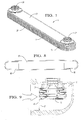
- Figure 1 is a perspective view of the oil cooler.
- Figure 2 is an exploded perspective view of the oil cooler.
- Figure 2Ais an enlargement of a portion of Figure 2.
- Figure 3 is a plan view of a plate and internal center.
- Figure 4 is a sectional view showing the plates secured along their perimeter.
- Figure 5 is an enlarged view showing the brace points formed by the plate seams.
- Figure 6 is a plan view of a top reinforcement having a flow diverter.
- Figure 7 is a sectional view of the top reinforcement having a flow diverter.
- Figure 8 is a plan view of the bottom reinforcement plate of the oil cooler.
- Figure 9 is a sectional environmental view of the oil cooler with a bottom reinforcement including a baffle.
-
- With reference to Figures 1 and 2, there is shown the aluminum
plate oil cooler 2 of the present invention. The aluminumplate oil cooler 2 includes a plurality of pairs ofplates 5 that are secured together around theirperimeter 10. The plurality of pairs ofplates 5 are separated from each other by anexternal center 15. There is also included, a top andbottom reinforcement top 27 andbottom 28 of the plurality of pairs ofplates 5. - With reference to Figure 2, the plurality of pairs of
plates 5 are secured along theirperimeter 10 such that theplates 5 are spaced from each other to define anoil flow path 30. Theplates 5 include embossedregions 35 formed on opposite ends of the plates for providing inlet and outlet ports, 37 and 39 respectively, for the oil to enter theoil flow path 30. - An
internal center 40 is positioned between theplates 5 and within theoil flow path 30 for transferring the heat from the oil within theoil flow path 30 to theplates 5. Theinternal center 40 increases the heat transfer by providing additional surface area for contact with the oil. Theinternal center 40 comprises a corrugated or folded sheet of metal forming generallyplaner fins 41 in side-by-side relationship enjoined bybends 42. Each of thefins 41 has a set oflouvers 43 extending over most of the fin area. Thefins 41 extend transverse to the direction of oil flow such that the oil must flow through thelouvers 43 of each fin to pass from theinlet 37 to theoutlet 39. The description of the type of internal center utilized by the present invention is similar in design to that disclosed in U.S. Patent No. 4,945,981 which is herein incorporated by reference. As stated previously, the design is similar but there are several differences which will be discussed further below. - As opposed to the internal centers disclosed in U.S. Patent No. 4,945,981, the
internal center 40 of the present invention extends along the entire surface of theplates 5 for providing increased strength to the aluminumplate oil cooler 2. Theembossments 35 are sized and configured such that theinterior center 40 extends around theembossment 35 inside theplate 5. Such an arrangement, has been demonstrated to increase the burst strength of the aluminum plate oil cooler by an additional 200 to 300 PSI. - The
internal center 40 andplates 5 are sized such that theinternal center 40, when placed in theoil flow path 30, has a clearance with theplates 5 that does not exceed .030 of an inch to eliminate oil bypass around theinternal center 40. Maintaining such a clearance between theinternal center 40 and theplates 5 increases the effectiveness of theinternal center 40 by eliminating bypass around thecenter 40 which could reduce the thermal effectiveness of the oil cooler. - As stated above, the
plates 5 are secured together along theirperimeter 10 and encapsulate theinternal center 40. Theplates 5 are clinched together to form a continuous male/female flange 50 which eliminates the possibility of seam leakage when clinched. Theplates 5 have a brazing clad placed on both sides of the plate to permanently attach the internal center within the plate, as well as to securely seal the continuous male/female flange 50. With reference to Figure 5, it can be seen that the continuous male/female flange 50 provides threepoints - With reference to Figures 1 and 2, an external center15 is positioned between each of the plurality of pairs of
plates 5 for increasing the heat transfer area from theplates 5 to a coolant. Theexternal center 15 comprises a corrugated aluminum sheet that has a plurality offins 17 formed thereon. Thefins 17 comprise first and second planer surfaces 18, 19 that are joined by a bend 16. Thefins 17 are formed such that the flow of coolant is perpendicular to the flow of oil in the internaloil flow path 30. As can be seen in Figures 1 and 2, theexternal center 15 covers the entire surface of theplates 5. This orientation provides a uniform internal load on theplates 5 during a brazing operation. The external load is provided by a brazing fixture and/or banding wires utilized during a brazing operation. The uniform internal load insures that a perfect bond between theinterior center 40 and theplates 5 is created. Theexternal center 15 includesholes 21 formed therein to correspond with theembossments 35. Theholes 21 allow theexternal center 15 to completely surround theembossments 35 providing additional support to the region around theembossments 35. - Again, with reference to Figures 1 and 2, the aluminum
plate oil cooler 2 of the present invention includes top andbottom reinforcements bottom reinforcements plates 5 to prevent theoil cooler 2 from brazing to a braze fixture during the brazing operation. Thetop reinforcement 20 may be made of any material which can braze to aluminum and exhibits the necessary structural properties to make a reinforcement. Because of the propensity of aluminum to erode or corrode under high fluid velocity conditions, it is advantageous to utilize a material for the reinforcement which demonstrates a high resistance to corrosion and/or erosion. The top reinforcement may be subjected to high fluid velocity conditions where the oil cooler is mounted such that it straddles a radiator inlet or outlet. Therefore, it is preferred that the top reinforcement comprise the 300 series of stainless steel, which is capable of brazing to aluminum, and demonstrates a high level of corrosion and erosion resistance. - In an alternative embodiment, the top reinforcement may include an
extended flow diverter 60 that may further prevent failures from occurring by directing high velocity fluids away from the aluminum components of the aluminumplate oil cooler 2. With reference to Figures 7 , it can be seen that theflow diverter 60 comprises an extension of the top reinforcement that extends outboard of theplates 5; thereby protecting them from corrosion or erosion from high velocity fluids from a radiator inlet or outlet. - For situations where the aluminum
plate oil cooler 2 has a plate stack height, meaning the number of plates that is only a small percentage of the radiator tank's width, the coolant has an opportunity to bypass theoil cooler 2. In such a situation, thebottom reinforcement 25 can include abaffle 67. With reference to Figure 8, there is shown a sectional view of anoil cooler 2 within a radiator tank that includes abaffle 67. Thebaffle 67 comprises anangled plate 69 that is formed at an angle of approximately 90 degrees to thebottom reinforcement 25 to direct the flow of coolant between the pairs ofplates 5 of the aluminumplate oil cooler 2. - While preferred embodiments are disclosed, a worker in this art would understand that various modifications would come within the scope of the invention. Thus, the following claims should be studied to determine the true scope and content of this invention.
Claims (9)
- A plate oil cooler (2) comprisinga plurality of pairs of plates (5) secured together along their perimeter (10), said plates (5) spaced from each other, thereby defining an oil flow path (30), said plates (5) including embossed regions (35) formed thereon for providing inlet (37) and outlet (39) ports for oil,top (20) and bottom (25) reinforcement plates positioned on a top (27) and bottom (28) of said plurality of pairs of plates (5); andan internal center (40) positioned between said plates (5) in thermal contact with said plates (5) and within said oil flow path (30) for transferring heat from the oil within the oil flow path (30) to said plates (5);an external center (15) positioned between each of said plurality of pairs (5) and in thermal contact with said plates(5) for increasing the heat transfer from said plates (5) to a coolant;said external center (15) comprising a corrugated aluminum sheet having a plurality of fins (17) having first (18) and second (19) planar surfaces joined by a bend (16), said fins (17) formed thereon such that the flow of coolant is perpendicular to the flow of oil;said external center (15) covering the entire surface of said plates (5) and including holes (21) formed therein to correspond with said embossed regions (35) for providing a uniform internal load on said plates (5) to ensure a bond between said internal center (15) and said plates during a brazing operation.
- The plate oil cooler (2) of Claim 1, wherein the external center (15) extends along the entire surface of said plates (5) for providing increased strength to the aluminum plate oil cooler (2).
- The plate oil cooler (2) of Claim 1, wherein a clearance between said internal center (40) and said plates (5) is less than .030 inches for eliminating oil bypass around said internal center (50).
- The plate oil cooler (2) of Claim 1, wherein said plates (5) are secured together along their perimeter (10) such that there are 3 points (51,52,53) where a braze joint may be formed in a brazing operation.
- The plate oil cooler (2) of Claim 1, wherein said top (20) and bottom (25) reinforcement plates are unclad for preventing a braze fixture brazing to said top (20) and bottom (25) reinforcement plates during a brazing operation.
- The plate oil cooler (2) of Claim 1, wherein said top reinforcement plate (20) comprises stainless steel.
- The plate oil cooler (2) of Claim 1, wherein said top reinforcement plate (20) comprises 300 series stainless steel.
- The plate oil cooler (2) of Claim 1, wherein said top reinforcement plate (20) further includes an extended flow director portion (60) formed thereon for preventing failures of said oil cooler (2) when said oil cooler (2) straddles a radiator outlet.
- The plate oil cooler of Claim 1, wherein said bottom (25) reinforcement plate further includes a baffle (67) formed thereon for directing the flow of a coolant.
Applications Claiming Priority (2)
| Application Number | Priority Date | Filing Date | Title |
|---|---|---|---|
| US781709 | 2001-02-12 | ||
| US09/781,709 US6341649B1 (en) | 2001-02-12 | 2001-02-12 | Aluminum plate oil cooler |
Publications (3)
| Publication Number | Publication Date |
|---|---|
| EP1231447A2 true EP1231447A2 (en) | 2002-08-14 |
| EP1231447A3 EP1231447A3 (en) | 2004-08-11 |
| EP1231447B1 EP1231447B1 (en) | 2010-04-07 |
Family
ID=25123648
Family Applications (1)
| Application Number | Title | Priority Date | Filing Date |
|---|---|---|---|
| EP02075106A Expired - Lifetime EP1231447B1 (en) | 2001-02-12 | 2002-01-14 | Aluminium plate oil cooler |
Country Status (5)
| Country | Link |
|---|---|
| US (1) | US6341649B1 (en) |
| EP (1) | EP1231447B1 (en) |
| JP (1) | JP3704315B2 (en) |
| AU (1) | AU776860B2 (en) |
| DE (1) | DE60235853D1 (en) |
Cited By (4)
| Publication number | Priority date | Publication date | Assignee | Title |
|---|---|---|---|---|
| DE10349141A1 (en) * | 2003-10-17 | 2005-05-12 | Behr Gmbh & Co Kg | Stacked plate heat exchangers, in particular oil coolers for motor vehicles |
| DE102004049988A1 (en) * | 2004-10-14 | 2006-04-20 | Modine Manufacturing Co., Racine | Plate heat exchanger |
| CN104220834A (en) * | 2012-03-19 | 2014-12-17 | 达纳加拿大公司 | Assembled components sandwiched between the walls of the annular plate |
| DE102014110459A1 (en) | 2014-07-24 | 2016-01-28 | Mahle International Gmbh | Heat exchanger |
Families Citing this family (22)
| Publication number | Priority date | Publication date | Assignee | Title |
|---|---|---|---|---|
| US20030131979A1 (en) * | 2001-12-19 | 2003-07-17 | Kim Hyeong-Ki | Oil cooler |
| KR100440176B1 (en) * | 2002-03-28 | 2004-07-14 | 위니아만도 주식회사 | Water-Cooling Type Oil Cooler for Vehicle |
| US20040173341A1 (en) * | 2002-04-25 | 2004-09-09 | George Moser | Oil cooler and production method |
| JP4338480B2 (en) * | 2003-09-05 | 2009-10-07 | カルソニックカンセイ株式会社 | Heat exchanger |
| DE102004007510B4 (en) * | 2004-02-13 | 2019-08-14 | Mahle International Gmbh | Heat exchangers, in particular oil coolers for motor vehicles |
| JP2006284137A (en) * | 2005-04-04 | 2006-10-19 | Denso Corp | Heat exchanger |
| FR2890733B1 (en) * | 2005-09-13 | 2013-07-12 | Valeo Systemes Thermiques | COLLECTOR BOX OF A FIRST HEAT EXCHANGER CONTAINING A SECOND HEAT EXCHANGER AND METHOD FOR MANUFACTURING THE SAME |
| US7516779B1 (en) | 2006-03-15 | 2009-04-14 | Proliance International Inc. | Concentric tube oil cooler |
| US20090183867A1 (en) * | 2008-01-23 | 2009-07-23 | Compressor Systems Inc. | Varying ambient heat exchanger for a compressor |
| DE102008007916A1 (en) * | 2008-02-06 | 2009-08-13 | Behr Gmbh & Co. Kg | Heat exchanger for charge air cooling, method for producing a heat exchanger for charge air cooling |
| KR101311035B1 (en) * | 2008-04-17 | 2013-09-24 | 다나 캐나다 코포레이션 | U-flow heat exchanger |
| EP2180158A1 (en) * | 2008-10-22 | 2010-04-28 | Perkins Engines Company Limited | Arrangement to control coolant flow in an engine |
| US20110024095A1 (en) * | 2009-07-30 | 2011-02-03 | Mark Kozdras | Heat Exchanger with End Plate Providing Mounting Flange |
| US8869398B2 (en) | 2011-09-08 | 2014-10-28 | Thermo-Pur Technologies, LLC | System and method for manufacturing a heat exchanger |
| DE102011090159A1 (en) * | 2011-12-30 | 2013-07-04 | Behr Gmbh & Co. Kg | Heat exchanger |
| US9631876B2 (en) * | 2013-03-19 | 2017-04-25 | Mahle International Gmbh | Heat exchanger |
| JP6329756B2 (en) | 2013-11-26 | 2018-05-23 | 株式会社マーレ フィルターシステムズ | Oil cooler |
| DE102014005149B4 (en) * | 2014-04-08 | 2016-01-21 | Modine Manufacturing Company | Brazed heat exchanger |
| PL3457066T3 (en) * | 2017-09-15 | 2022-08-16 | Alfa Laval Corporate Ab | Baffle |
| KR102676721B1 (en) * | 2019-04-24 | 2024-06-18 | 현대자동차주식회사 | Cooling system for power conversion device |
| CN113931731B (en) * | 2021-09-26 | 2022-07-01 | 江苏力德热交换系统有限公司 | Automobile radiator based on integral frame type design |
| DE102021213357A1 (en) * | 2021-11-26 | 2023-06-01 | Robert Bosch Gesellschaft mit beschränkter Haftung | Cooling device for cooling electronic components |
Citations (1)
| Publication number | Priority date | Publication date | Assignee | Title |
|---|---|---|---|---|
| US4945981A (en) | 1990-01-26 | 1990-08-07 | General Motors Corporation | Oil cooler |
Family Cites Families (16)
| Publication number | Priority date | Publication date | Assignee | Title |
|---|---|---|---|---|
| US821422A (en) * | 1904-08-12 | 1906-05-22 | D Mcra Livingston | Cooling apparatus. |
| US4815532A (en) * | 1986-02-28 | 1989-03-28 | Showa Aluminum Kabushiki Kaisha | Stack type heat exchanger |
| FR2614687A1 (en) * | 1987-04-30 | 1988-11-04 | Chausson Usines Sa | Annular heat exchanger |
| CA1313183C (en) * | 1989-02-24 | 1993-01-26 | Allan K. So | Embossed plate heat exchanger |
| US5014775A (en) * | 1990-05-15 | 1991-05-14 | Toyo Radiator Co., Ltd. | Oil cooler and manufacturing method thereof |
| EP0612396B1 (en) | 1991-11-15 | 1998-01-07 | Long Manufacturing Ltd. | In tank oil cooler |
| US5329994A (en) * | 1992-12-23 | 1994-07-19 | Sundstrand Corporation | Jet impingement heat exchanger |
| US5638900A (en) * | 1995-01-27 | 1997-06-17 | Ail Research, Inc. | Heat exchange assembly |
| CA2153528C (en) * | 1995-07-10 | 2006-12-05 | Bruce Laurance Evans | Plate heat exchanger with reinforced input/output manifolds |
| ES2146459T3 (en) * | 1996-02-01 | 2000-08-01 | Northern Res & Eng | PLATE HEAT EXCHANGER WITH FINS. |
| US5636685A (en) | 1996-08-16 | 1997-06-10 | General Motors Corporation | Plate and fin oil cooler with improved efficiency |
| SE511071C2 (en) * | 1996-11-19 | 1999-08-02 | Valeo Engine Cooling Ab | Flat oil coolers where flow reducing means are arranged in the closest inside the outer oil channels |
| ES2192698T3 (en) * | 1996-12-05 | 2003-10-16 | Showa Denko Kk | HEAT EXCHANGER. |
| JP3814917B2 (en) * | 1997-02-26 | 2006-08-30 | 株式会社デンソー | Stacked evaporator |
| JP2000329493A (en) * | 1999-05-20 | 2000-11-30 | Toyo Radiator Co Ltd | Lamination-type heat exchanger |
| CA2272804C (en) * | 1999-05-28 | 2004-07-20 | Long Manufacturing Ltd. | Heat exchanger with dimpled bypass channel |
-
2001
- 2001-02-12 US US09/781,709 patent/US6341649B1/en not_active Expired - Lifetime
-
2002
- 2002-01-10 AU AU10120/02A patent/AU776860B2/en not_active Ceased
- 2002-01-14 EP EP02075106A patent/EP1231447B1/en not_active Expired - Lifetime
- 2002-01-14 DE DE60235853T patent/DE60235853D1/en not_active Expired - Lifetime
- 2002-01-15 JP JP2002006278A patent/JP3704315B2/en not_active Expired - Fee Related
Patent Citations (1)
| Publication number | Priority date | Publication date | Assignee | Title |
|---|---|---|---|---|
| US4945981A (en) | 1990-01-26 | 1990-08-07 | General Motors Corporation | Oil cooler |
Cited By (6)
| Publication number | Priority date | Publication date | Assignee | Title |
|---|---|---|---|---|
| DE10349141A1 (en) * | 2003-10-17 | 2005-05-12 | Behr Gmbh & Co Kg | Stacked plate heat exchangers, in particular oil coolers for motor vehicles |
| US7717164B2 (en) | 2003-10-17 | 2010-05-18 | Behr Gmbh & Co. Kg | Stacked plate heat exchanger in particular an oil cooler for motor vehicles |
| DE102004049988A1 (en) * | 2004-10-14 | 2006-04-20 | Modine Manufacturing Co., Racine | Plate heat exchanger |
| CN104220834A (en) * | 2012-03-19 | 2014-12-17 | 达纳加拿大公司 | Assembled components sandwiched between the walls of the annular plate |
| CN104220834B (en) * | 2012-03-19 | 2018-06-05 | 达纳加拿大公司 | Weld Assembly Components |
| DE102014110459A1 (en) | 2014-07-24 | 2016-01-28 | Mahle International Gmbh | Heat exchanger |
Also Published As
| Publication number | Publication date |
|---|---|
| EP1231447B1 (en) | 2010-04-07 |
| AU1012002A (en) | 2002-08-15 |
| DE60235853D1 (en) | 2010-05-20 |
| JP2002267385A (en) | 2002-09-18 |
| JP3704315B2 (en) | 2005-10-12 |
| EP1231447A3 (en) | 2004-08-11 |
| US6341649B1 (en) | 2002-01-29 |
| AU776860B2 (en) | 2004-09-23 |
Similar Documents
| Publication | Publication Date | Title |
|---|---|---|
| US6341649B1 (en) | Aluminum plate oil cooler | |
| US6595271B2 (en) | Heat exchanger of aluminum | |
| US8678076B2 (en) | Heat exchanger with manifold strengthening protrusion | |
| US7182125B2 (en) | Low profile heat exchanger with notched turbulizer | |
| US4529034A (en) | Heat exchanger having a header plate | |
| JP2005517893A (en) | Finned low profile heat exchanger | |
| US7237605B2 (en) | Heat exchanger | |
| EP1172623B1 (en) | Heat exchanger and fluid pipe therefor | |
| US20110036547A1 (en) | Plate Heat Exchanger | |
| JP2007518958A (en) | Heat exchangers, especially oil / coolant coolers | |
| WO2008091918A1 (en) | Heat exchanger and method | |
| US8646516B2 (en) | Alternating plate headerless heat exchangers | |
| JP2007093023A (en) | Heat exchanger | |
| CN113383205A (en) | Heat exchanger | |
| JPH033160B2 (en) | ||
| JPH08159686A (en) | Laminate type heat exchanger core | |
| EP2057434B1 (en) | Alternating plate headerless heat exchangers | |
| JP2018155468A (en) | Heat exchanger | |
| US20060048930A1 (en) | Heat exchanger | |
| JPS6321495A (en) | Lamination type heat exchanger | |
| JP4225744B2 (en) | Heat exchanger | |
| AU2003264630B2 (en) | Brazed Sheets With Aligned Openings and Heat Exchanger Formed Therefrom | |
| JP2005037031A (en) | Joining structure of heat exchanger | |
| JP2018197627A (en) | Heat exchanger | |
| KR19990037819A (en) | Manifold for engine of ship |
Legal Events
| Date | Code | Title | Description |
|---|---|---|---|
| PUAI | Public reference made under article 153(3) epc to a published international application that has entered the european phase |
Free format text: ORIGINAL CODE: 0009012 |
|
| AK | Designated contracting states |
Kind code of ref document: A2 Designated state(s): AT BE CH CY DE DK ES FI FR GB GR IE IT LI LU MC NL PT SE TR |
|
| AX | Request for extension of the european patent |
Free format text: AL;LT;LV;MK;RO;SI |
|
| PUAL | Search report despatched |
Free format text: ORIGINAL CODE: 0009013 |
|
| AK | Designated contracting states |
Kind code of ref document: A3 Designated state(s): AT BE CH CY DE DK ES FI FR GB GR IE IT LI LU MC NL PT SE TR |
|
| AX | Request for extension of the european patent |
Extension state: AL LT LV MK RO SI |
|
| 17P | Request for examination filed |
Effective date: 20050211 |
|
| AKX | Designation fees paid |
Designated state(s): DE FR GB |
|
| RBV | Designated contracting states (corrected) |
Designated state(s): DE FR GB |
|
| 17Q | First examination report despatched |
Effective date: 20090121 |
|
| GRAP | Despatch of communication of intention to grant a patent |
Free format text: ORIGINAL CODE: EPIDOSNIGR1 |
|
| GRAS | Grant fee paid |
Free format text: ORIGINAL CODE: EPIDOSNIGR3 |
|
| GRAA | (expected) grant |
Free format text: ORIGINAL CODE: 0009210 |
|
| AK | Designated contracting states |
Kind code of ref document: B1 Designated state(s): DE FR GB |
|
| REG | Reference to a national code |
Ref country code: GB Ref legal event code: FG4D |
|
| REF | Corresponds to: |
Ref document number: 60235853 Country of ref document: DE Date of ref document: 20100520 Kind code of ref document: P |
|
| PLBE | No opposition filed within time limit |
Free format text: ORIGINAL CODE: 0009261 |
|
| STAA | Information on the status of an ep patent application or granted ep patent |
Free format text: STATUS: NO OPPOSITION FILED WITHIN TIME LIMIT |
|
| 26N | No opposition filed |
Effective date: 20110110 |
|
| REG | Reference to a national code |
Ref country code: DE Ref legal event code: R082 Ref document number: 60235853 Country of ref document: DE Representative=s name: BRP RENAUD UND PARTNER MBB RECHTSANWAELTE PATE, DE Ref country code: DE Ref legal event code: R082 Ref document number: 60235853 Country of ref document: DE Representative=s name: BRP RENAUD UND PARTNER MBB, DE Ref country code: DE Ref legal event code: R081 Ref document number: 60235853 Country of ref document: DE Owner name: MAHLE INTERNATIONAL GMBH, DE Free format text: FORMER OWNER: DELPHI TECHNOLOGIES, INC., TROY, MICH., US |
|
| REG | Reference to a national code |
Ref country code: FR Ref legal event code: PLFP Year of fee payment: 15 |
|
| REG | Reference to a national code |
Ref country code: GB Ref legal event code: 732E Free format text: REGISTERED BETWEEN 20161208 AND 20161214 |
|
| REG | Reference to a national code |
Ref country code: FR Ref legal event code: PLFP Year of fee payment: 16 |
|
| REG | Reference to a national code |
Ref country code: FR Ref legal event code: PLFP Year of fee payment: 17 |
|
| REG | Reference to a national code |
Ref country code: FR Ref legal event code: TP Owner name: MAHLE INTERNATIONAL GMBH, DE Effective date: 20180103 |
|
| PGFP | Annual fee paid to national office [announced via postgrant information from national office to epo] |
Ref country code: GB Payment date: 20200129 Year of fee payment: 19 |
|
| PGFP | Annual fee paid to national office [announced via postgrant information from national office to epo] |
Ref country code: FR Payment date: 20200128 Year of fee payment: 19 |
|
| PGFP | Annual fee paid to national office [announced via postgrant information from national office to epo] |
Ref country code: DE Payment date: 20210329 Year of fee payment: 20 |
|
| GBPC | Gb: european patent ceased through non-payment of renewal fee |
Effective date: 20210114 |
|
| PG25 | Lapsed in a contracting state [announced via postgrant information from national office to epo] |
Ref country code: FR Free format text: LAPSE BECAUSE OF NON-PAYMENT OF DUE FEES Effective date: 20210131 |
|
| PG25 | Lapsed in a contracting state [announced via postgrant information from national office to epo] |
Ref country code: GB Free format text: LAPSE BECAUSE OF NON-PAYMENT OF DUE FEES Effective date: 20210114 |
|
| REG | Reference to a national code |
Ref country code: DE Ref legal event code: R071 Ref document number: 60235853 Country of ref document: DE |