EP1231420A2 - Methods and apparatus for reducing seal teeth wear - Google Patents
Methods and apparatus for reducing seal teeth wear Download PDFInfo
- Publication number
- EP1231420A2 EP1231420A2 EP02250818A EP02250818A EP1231420A2 EP 1231420 A2 EP1231420 A2 EP 1231420A2 EP 02250818 A EP02250818 A EP 02250818A EP 02250818 A EP02250818 A EP 02250818A EP 1231420 A2 EP1231420 A2 EP 1231420A2
- Authority
- EP
- European Patent Office
- Prior art keywords
- seal
- honeycomb
- teeth
- gas turbine
- turbine engine
- Prior art date
- Legal status (The legal status is an assumption and is not a legal conclusion. Google has not performed a legal analysis and makes no representation as to the accuracy of the status listed.)
- Withdrawn
Links
Images


Classifications
-
- F—MECHANICAL ENGINEERING; LIGHTING; HEATING; WEAPONS; BLASTING
- F01—MACHINES OR ENGINES IN GENERAL; ENGINE PLANTS IN GENERAL; STEAM ENGINES
- F01D—NON-POSITIVE DISPLACEMENT MACHINES OR ENGINES, e.g. STEAM TURBINES
- F01D11/00—Preventing or minimising internal leakage of working-fluid, e.g. between stages
- F01D11/08—Preventing or minimising internal leakage of working-fluid, e.g. between stages for sealing space between rotor blade tips and stator
- F01D11/12—Preventing or minimising internal leakage of working-fluid, e.g. between stages for sealing space between rotor blade tips and stator using a rubstrip, e.g. erodible. deformable or resiliently-biased part
- F01D11/127—Preventing or minimising internal leakage of working-fluid, e.g. between stages for sealing space between rotor blade tips and stator using a rubstrip, e.g. erodible. deformable or resiliently-biased part with a deformable or crushable structure, e.g. honeycomb
-
- F—MECHANICAL ENGINEERING; LIGHTING; HEATING; WEAPONS; BLASTING
- F01—MACHINES OR ENGINES IN GENERAL; ENGINE PLANTS IN GENERAL; STEAM ENGINES
- F01D—NON-POSITIVE DISPLACEMENT MACHINES OR ENGINES, e.g. STEAM TURBINES
- F01D5/00—Blades; Blade-carrying members; Heating, heat-insulating, cooling or antivibration means on the blades or the members
- F01D5/12—Blades
- F01D5/22—Blade-to-blade connections, e.g. for damping vibrations
- F01D5/225—Blade-to-blade connections, e.g. for damping vibrations by shrouding
-
- F—MECHANICAL ENGINEERING; LIGHTING; HEATING; WEAPONS; BLASTING
- F16—ENGINEERING ELEMENTS AND UNITS; GENERAL MEASURES FOR PRODUCING AND MAINTAINING EFFECTIVE FUNCTIONING OF MACHINES OR INSTALLATIONS; THERMAL INSULATION IN GENERAL
- F16J—PISTONS; CYLINDERS; SEALINGS
- F16J15/00—Sealings
- F16J15/44—Free-space packings
- F16J15/444—Free-space packings with facing materials having honeycomb-like structure
-
- Y—GENERAL TAGGING OF NEW TECHNOLOGICAL DEVELOPMENTS; GENERAL TAGGING OF CROSS-SECTIONAL TECHNOLOGIES SPANNING OVER SEVERAL SECTIONS OF THE IPC; TECHNICAL SUBJECTS COVERED BY FORMER USPC CROSS-REFERENCE ART COLLECTIONS [XRACs] AND DIGESTS
- Y02—TECHNOLOGIES OR APPLICATIONS FOR MITIGATION OR ADAPTATION AGAINST CLIMATE CHANGE
- Y02T—CLIMATE CHANGE MITIGATION TECHNOLOGIES RELATED TO TRANSPORTATION
- Y02T50/00—Aeronautics or air transport
- Y02T50/60—Efficient propulsion technologies, e.g. for aircraft
Definitions
- This invention relates generally to gas turbine engines and, more particularly, to honeycomb seals included in gas turbine engines.
- Honeycomb seals are widely used in aircraft, marine and industrial power turbine engines.
- a gas turbine engine typically includes at least one row of rotor blades and a plurality of honeycomb seals within cavities formed in a rotor assembly.
- honeycomb materials having a melting temperature over 2100°F e.g., Hastelloy X
- seal teeth located on a first rotatable annular member cut grooves or channels into the honeycomb seals located on either a second non-rotatable member or a second rotatable member having a different rotation speed than that of the first rotatable member.
- the channels cut by the first rotatable annular member with seal teeth define an operating clearance between the seal teeth and the honeycomb material, and permit the honeycomb material to seal against the seal teeth to restrict air from flowing between the cavities formed by the seal teeth and honeycomb material.
- the seal teeth cut into the honeycomb material with low incursion rates.
- High or rapid incursion rates may develop, for example, as a result of tight tolerances. Additional high incursion rates may occur after maintenance is performed to existing turbines and after turbine module components are interchanged or replaced.
- frictional heat generated between the seal teeth and honeycomb material increases from a normal operating temperature to a value below that of the melting temperature of the honeycomb material.
- the seal teeth do not effectively cut into the honeycomb material, but rather the honeycomb cells yield and "smear" when contacted with the seal teeth. Because the seal teeth do not effectively cut the honeycomb material, a high seal rubbing torque develops and the frictional heat generated between the seal teeth and the honeycomb material is further increased.
- the increased temperature induced within the seal teeth causes potential material degradation, possible fatigue cracking and possible quench cracking of the seal teeth. Over time, continued exposure to high temperatures may result in the seal teeth exceeding a yield stress, thus resulting in residual stresses that may reduce fatigue life and degradation of the seal teeth. Furthermore, if the honeycomb material is not positioned a uniform distance from the rotating member blades circumferentially around the turbine, local rubbing may occur. The combination of the local rubbing and the increased temperature of the seal teeth may produce sinusoidal thermal gradients and deeper rubs into the honeycomb material. Furthermore, as a result of the deeper rubs, operating clearances are increased locally, and air may flow between the rotating member and honeycomb material, decreasing an effectiveness of the seal.
- a gas turbine engine in an exemplary embodiment of the invention, includes a non-rotating assembly including a honeycomb seal that reduces wear to seal teeth disposed within the gas turbine engine.
- the gas turbine engine non-rotating assembly includes a sealing assembly disposed between rotor components and stator components.
- the rotor components include a rotatable annular member including seal teeth extending radially outward from the rotatable annular member.
- the stator components include a non-rotatable member including a honeycomb seal that extends radially inward.
- the honeycomb seal is fabricated from a material that has a melting temperature less than approximately 2000° F.
- the rotating seal teeth contact the honeycomb material and generate a temperature that is not greater than the melting temperature of the honeycomb material. Accordingly, as the seal teeth contact the honeycomb material, grooves or channels are cut easily into the honeycomb by the seal teeth. The channels define an operating clearance between the blade seal teeth and the honeycomb material, and permit the honeycomb material to seal against the seal teeth to restrict air from flowing between the seal teeth and honeycomb material. Because the melting temperature of the honeycomb seal is less than 2000°F, a temperature increase generated when the rotating seal teeth cut into the honeycomb seal is limited to a temperature less than the melting temperature of the honeycomb material.
- the melting temperature of the honeycomb material is less than 2000°F, the temperature increase induced within the seal teeth is reduced in comparison to temperature increases induced in seal teeth cutting through known honeycomb seals fabricated from materials with higher melting temperatures. As a result, property degradation to the seal teeth and cracking due to thermal stresses are reduced.
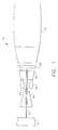
- FIG. 1 is a schematic illustration of a gas turbine engine 10 including a low pressure compressor 12, a high pressure compressor 14, and a combustor 16.
- engine 10 includes a high pressure turbine 18 and a low pressure turbine 20.
- Compressor 12 and turbine 20 are coupled by a first shaft 21, and compressor 14 and turbine 18 are coupled by a second shaft 22.
- the highly compressed air is delivered to combustor 16.
- Airflow from combustor 16 drives rotating turbines 18 and 20 and exits gas turbine engine 10 through a nozzle 24.
- FIG 2 is a partial schematic view of a rotor assembly 100 that may be used with a gas turbine engine, such as gas turbine engine 10 (shown in Figure 1).
- rotor assembly 100 includes a honeycomb seal 102, a plurality of stator vanes 104, and at least one rotating member.
- Rotating member 106 includes a tip 108 having at least one seal tooth 110 extending outward therefrom towards a casing 112.
- Casing 112 is disposed radially outward from stator vanes 104 and rotating member 106.
- Honeycomb seal 102 extends circumferentially around rotating member 106 and includes a first end 114 and a second end 116 attached to casing 112. Honeycomb seal first end 114 is attached to casing 112 with a first connector 118 and honeycomb seal second end 116 is attached to casing 112 with a second connector 120. Second connector 120 provides a spring force to second end 116 of honeycomb seal 102 to push honeycomb seal 102 into contact with a stator vane platform 122 such that when engine 100 is inoperative, seal teeth 110 are a distance 126 from honeycomb seal 102.
- honeycomb seal 102 contains material 130, described in more detail below, and is assembled into casing 112 at first end 114 such that an axial projection 132 is received within an axial groove 134 in casing 112.
- seal teeth 110 are a distance 126 from honeycomb seal 102.
- seal teeth 110 expand radially outward and contact or rub honeycomb seal 102 and cut grooves (not shown) into honeycomb seal 102 to define an operating clearance (not shown) between seal teeth 110 and honeycomb seal 102.
- seal teeth 110 rotate via a rotor (not shown) with respect to casing 112, and stator vanes 104 remain stationary with respect to casing 112. Air flows from an upstream side 138 of turbine 100 to a downstream side 140 of turbine 100. After turbine 100 operates and reaches a sufficient operating temperature, seal teeth 110 extend into honeycomb seal 102 and restrict air from flowing between seal teeth 110 and honeycomb seal 102.
- FIG 3 is an enlarged end view of honeycomb seal 102.
- Honeycomb seal 102 is fabricated from material 130 formed of a plurality of thin corrugated strips 152 mated together in a honeycomb configuration 154.
- Honeycomb configuration 154 includes a plurality of cells 156 and a plurality of cell walls 158 separating each cell 156.
- cells 156 have a hexagon shape.
- cells 156 could have a circular, triangular, rectangular, pentagon, or other shape.
- Material 130 has intrinsic properties that permit honeycomb seal 102 to withstand harsh environmental conditions prevalent during engine operations.
- material 130 can withstand exposure to a high range of temperatures and pressures, and has a melting temperature below approximately 2000°F.
- material 130 is composed of an alloy material possessing a melting temperature of approximately 1930 °F.
- honeycomb material 130 is brass and has a melting temperature of approximately 1650°F.
- honeycomb material 130 is aluminum and has a melting temperature of approximately 1050°F.
- material 130 is any other suitable material or composite material that is environmentally resistive and has a melting temperature less than 2000°F.
- an operating temperature of seal teeth 110 increases during rubbing with honeycomb seal 102 to a temperature that is not greater than the melting temperature of honeycomb seal material 130. Because the melting temperature of honeycomb seal 102 is less than 2000°F, a temperature increase induced within seal teeth 110 is limited to less than approximately 2000°F and is reduced during rubbing between seal teeth 110 and honeycomb seal 102. Furthermore, because the seal teeth cutter temperature increase is reduced, an impact to seal teeth cutter properties of rubbing honeycomb seal 102 is reduced. Specifically, because heat damage to seal teeth 110 is reduced seal teeth durability is improved. Additionally, property degradation to seal teeth 110 and cracking due to thermal stresses are reduced.
- seal teeth 110 lowering the potential temperature increase of seal teeth 110 during rubbing also reduces residual stresses induced within seal teeth 110 that develop when yield stresses for seal teeth 110 are exceeded. In addition, the reduced temperature increase results in less torque being produced between seal teeth 110 and honeycomb seal 102, thus, causing less wear of seal teeth 110. Furthermore, the reduced temperature increase facilitates reducing crack initiation within honeycomb seal 102 and fatigue degradation of honeycomb seal 102.
- a honeycomb seal 102 is installed within a gas turbine engine 100 (shown in Figure 1) such that distance 126 (shown in Figure 2) is not circumferentially uniform around gas turbine engine 100, during operation of engine 100, local rubbing between seal teeth 110 and honeycomb seal 102 may occur. Heat generated between seal teeth 110 and honeycomb 102 during occurrences of local rubbing sinusoidal thermal gradients may be induced within seal teeth 110. Over time, if such sinusoidal thermal gradients are severe, wider operating clearances may develop. The severity of such sinusoidal thermal gradients is proportional to an amount of heat input into seal teeth 102. Accordingly, because the potential temperature increase of seal teeth 110 is reduced, the severity of any sinusoidal thermal gradients generated is reduced and operating clearances between seal teeth 110 and honeycomb seal 102 are improved.
- Figure 4 is a partial schematic view of a portion of gas turbine engine 10 including a labyrinth seal 200 that may be used with gas turbine engine 10.
- Labyrinth seal 200 is suitably mounted to a first rotatable annular member 202 including a plurality of seal teeth 204 extending radially from an outer peripheral surface 206 of rotatable annular member 202 to define an outer circumference of seal teeth 204.
- honeycomb seal 208 is suitably mounted to a second non-rotatable member 210 and extends radially inward to define an inner circumference of honeycomb seal 208.
- Honeycomb seal 208 extends circumferentially around rotating member 202 and is fabricated substantially similarly with honeycomb seal 102 (shown in Figure 2) from a material 130 (shown in Figure 3).
- honeycomb seal 208 may be a labyrinth seal (not shown) disposed in a cavity (not shown) between seal teeth 204 located on a first rotatable annular member 202 and a second rotatable member (not shown) that has a different rotation speed than that of first rotatable member 202.
- seal teeth 204 rotate within a small tolerance of inner circumference of honeycomb seal 208 thereby effecting a sealing between axially disposed portions of engine 10.
- seal teeth 204 may expand radially outward and contact or rub honeycomb seal 208 and cut grooves (not shown) into honeycomb seal 208 to define an operating clearance (not shown) between seal teeth 204 and honeycomb seal 208.
- seal teeth 204 rotate via rotatable member 202. After turbine 10 operates and reaches a sufficient operating temperature, seal teeth 204 extend into honeycomb seal 208 and restrict air from flowing between seal teeth 204 and honeycomb seal 208.
- the above-described gas turbine engine is cost-effective and highly reliable.
- the stator assembly includes a honeycomb seal that is fabricated from a material that has a melting temperature less than approximately 2000°F.
- the seal teeth contact the honeycomb seal and generate heat to increase in temperature to a temperature that is not greater than the melting temperature of the honeycomb seal.
- the honeycomb seal seals against the seal teeth to prevent air from flowing between the seal and seal teeth.
- the melting temperature of the honeycomb seal material limits an operating temperature of the seal teeth during the rub.
- the seal teeth operate at reduced temperatures in comparison to known seal teeth and are subjected to less thermal stresses and wear.
- seal teeth durability is improved. Furthermore, property degradation to seal teeth and cracking due to thermal stresses are reduced. Accordingly, because the potential temperature increase during a rub of the seal teeth is reduced, the severity of any thermal gradients generated is reduced and operating clearances between the seal teeth and the honeycomb seal are improved.
Landscapes
- Engineering & Computer Science (AREA)
- General Engineering & Computer Science (AREA)
- Mechanical Engineering (AREA)
- Turbine Rotor Nozzle Sealing (AREA)
- Sealing Devices (AREA)
- Sealing Using Fluids, Sealing Without Contact, And Removal Of Oil (AREA)
Abstract
Description
Claims (10)
- A method for assembling a gas turbine engine (10), said method comprising the steps of:fabricating a honeycomb seal (102) from a material (130) having a melting temperature less than approximately 2000° F; andsecuring the seal within the gas turbine engine.
- A honeycomb seal (102) for a gas turbine engine(10), said seal comprising a material (130) having a melting temperature less than approximately 2000° F.
- A honeycomb seal (102) in accordance with Claim 2 wherein the gas turbine engine (10) includes a plurality of seal teeth (110), said honeycomb seal configured to reduce an operating temperature of the seal teeth as the seal teeth rub said honeycomb seal.
- A honeycomb seal (102) in accordance with Claim 2 wherein the gas turbine engine (10) includes a plurality of seal teeth (110), said honeycomb seal configured to reduce wear of the seal teeth as the seal teeth rub said honeycomb seal.
- A honeycomb seal (102) in accordance with Claim 2 wherein wherein the gas turbine engine (10) includes a plurality of rotor seal teeth (110), said material (130) configured to facilitate reducing a propensity of crack initiation within said honeycomb seal.
- A honeycomb seal (102) in accordance with Claim 5 wherein said material (130) further configured to facilitate reducing fatigue degradation of the rotor seal teeth (110).
- A honeycomb seal (102) in accordance with Claim 2 wherein said material (130) has a melting temperature greater than approximately 1600° F.
- A honeycomb seal (102) in accordance with Claim 2 wherein the gas turbine engine (10) includes a plurality of seal teeth (110), said honeycomb seal configured to reduce an operating clearance between said honeycomb seal and the seal teeth.
- A gas turbine engine (10) comprising a rotor assembly (100) and a stator assembly comprising a honeycomb seal (102) in accordance with any one of claims 2 to 8.
- A gas turbine engine (10) in accordance with Claim 9 wherein said material (130) has a melting temperature approximately equal 1930° F.
Applications Claiming Priority (2)
| Application Number | Priority Date | Filing Date | Title |
|---|---|---|---|
| US783277 | 1991-10-28 | ||
| US09/783,277 US6652226B2 (en) | 2001-02-09 | 2001-02-09 | Methods and apparatus for reducing seal teeth wear |
Publications (2)
| Publication Number | Publication Date |
|---|---|
| EP1231420A2 true EP1231420A2 (en) | 2002-08-14 |
| EP1231420A3 EP1231420A3 (en) | 2004-08-11 |
Family
ID=25128722
Family Applications (1)
| Application Number | Title | Priority Date | Filing Date |
|---|---|---|---|
| EP02250818A Withdrawn EP1231420A3 (en) | 2001-02-09 | 2002-02-07 | Methods and apparatus for reducing seal teeth wear |
Country Status (3)
| Country | Link |
|---|---|
| US (1) | US6652226B2 (en) |
| EP (1) | EP1231420A3 (en) |
| JP (1) | JP4474088B2 (en) |
Cited By (6)
| Publication number | Priority date | Publication date | Assignee | Title |
|---|---|---|---|---|
| WO2006076881A1 (en) * | 2005-01-18 | 2006-07-27 | Mtu Aero Engines Gmbh | Power plant with sealing device |
| EP2728122A1 (en) * | 2012-10-30 | 2014-05-07 | MTU Aero Engines GmbH | Blade outer air seal fixing for a fluid flow engine |
| CN103890320A (en) * | 2011-10-28 | 2014-06-25 | 通用电气公司 | High temperature sealing system |
| EP2881545A1 (en) * | 2013-12-04 | 2015-06-10 | MTU Aero Engines GmbH | Sealing element, sealing device and gas turbine engine |
| CN106988806A (en) * | 2016-01-21 | 2017-07-28 | 通用电气公司 | Improve the stream alignment device of diffuser performance |
| EP3090138A4 (en) * | 2013-12-03 | 2017-10-18 | United Technologies Corporation | Heat shields for air seals |
Families Citing this family (39)
| Publication number | Priority date | Publication date | Assignee | Title |
|---|---|---|---|---|
| US7059821B2 (en) * | 2003-05-07 | 2006-06-13 | General Electric Company | Method and apparatus to facilitate sealing within turbines |
| US20040239040A1 (en) * | 2003-05-29 | 2004-12-02 | Burdgick Steven Sebastian | Nozzle interstage seal for steam turbines |
| US7234918B2 (en) * | 2004-12-16 | 2007-06-26 | Siemens Power Generation, Inc. | Gap control system for turbine engines |
| US7341426B2 (en) * | 2004-12-29 | 2008-03-11 | United Technologies Corporation | Gas turbine engine blade tip clearance apparatus and method |
| US8011883B2 (en) * | 2004-12-29 | 2011-09-06 | United Technologies Corporation | Gas turbine engine blade tip clearance apparatus and method |
| US7407369B2 (en) * | 2004-12-29 | 2008-08-05 | United Technologies Corporation | Gas turbine engine blade tip clearance apparatus and method |
| US20070132193A1 (en) * | 2005-12-13 | 2007-06-14 | Wolfe Christopher E | Compliant abradable sealing system and method for rotary machines |
| US20070137039A1 (en) * | 2005-12-20 | 2007-06-21 | General Electric Company | Methods and apparatus for coupling honeycomb seals to gas turbine engine components |
| FR2899274B1 (en) * | 2006-03-30 | 2012-08-17 | Snecma | DEVICE FOR FASTENING RING SECTIONS AROUND A TURBINE WHEEL OF A TURBOMACHINE |
| US8074998B2 (en) * | 2006-05-05 | 2011-12-13 | The Texas A&M University System | Annular seals for non-contact sealing of fluids in turbomachinery |
| US20070273104A1 (en) * | 2006-05-26 | 2007-11-29 | Siemens Power Generation, Inc. | Abradable labyrinth tooth seal |
| US7511516B2 (en) * | 2006-06-13 | 2009-03-31 | General Electric Company | Methods and systems for monitoring the displacement of turbine blades |
| US7971882B1 (en) * | 2007-01-17 | 2011-07-05 | Florida Turbine Technologies, Inc. | Labyrinth seal |
| US20090097979A1 (en) * | 2007-07-31 | 2009-04-16 | Omer Duane Erdmann | Rotor blade |
| US20090072488A1 (en) * | 2007-09-18 | 2009-03-19 | Honeywell International, Inc. | Labyrinth seals and methods of manufacture |
| FR2923525B1 (en) * | 2007-11-13 | 2009-12-18 | Snecma | SEALING A ROTOR RING IN A TURBINE FLOOR |
| US8282346B2 (en) * | 2009-04-06 | 2012-10-09 | General Electric Company | Methods, systems and/or apparatus relating to seals for turbine engines |
| DE102009016803A1 (en) * | 2009-04-09 | 2010-10-14 | Rolls-Royce Deutschland Ltd & Co Kg | Labyrinth rubbing seal for a turbomachine |
| US8608424B2 (en) * | 2009-10-09 | 2013-12-17 | General Electric Company | Contoured honeycomb seal for a turbomachine |
| US8939715B2 (en) * | 2010-03-22 | 2015-01-27 | General Electric Company | Active tip clearance control for shrouded gas turbine blades and related method |
| US20130017070A1 (en) * | 2011-07-13 | 2013-01-17 | General Electric Company | Turbine seal, turbine, and process of fabricating a turbine seal |
| US9109458B2 (en) | 2011-11-11 | 2015-08-18 | United Technologies Corporation | Turbomachinery seal |
| US9109608B2 (en) * | 2011-12-15 | 2015-08-18 | Siemens Energy, Inc. | Compressor airfoil tip clearance optimization system |
| US9291061B2 (en) * | 2012-04-13 | 2016-03-22 | General Electric Company | Turbomachine blade tip shroud with parallel casing configuration |
| US8936431B2 (en) | 2012-06-08 | 2015-01-20 | General Electric Company | Shroud for a rotary machine and methods of assembling same |
| US9574455B2 (en) * | 2012-07-16 | 2017-02-21 | United Technologies Corporation | Blade outer air seal with cooling features |
| US9115596B2 (en) * | 2012-08-07 | 2015-08-25 | United Technologies Corporation | Blade outer air seal having anti-rotation feature |
| US20140064969A1 (en) * | 2012-08-29 | 2014-03-06 | Dmitriy A. Romanov | Blade outer air seal |
| US9194247B2 (en) | 2012-11-14 | 2015-11-24 | General Electric Company | Rotating seal configuration and method of sealing a rotating member to a housing |
| US9803491B2 (en) * | 2012-12-31 | 2017-10-31 | United Technologies Corporation | Blade outer air seal having shiplap structure |
| JP6184173B2 (en) | 2013-05-29 | 2017-08-23 | 三菱日立パワーシステムズ株式会社 | gas turbine |
| JP6271077B2 (en) | 2014-07-24 | 2018-01-31 | シーメンス アクチエンゲゼルシヤフトSiemens Aktiengesellschaft | Stator vane system for use in gas turbine engines |
| CA2932601C (en) | 2015-06-17 | 2023-10-03 | Rolls-Royce Corporation | Labyrinth seal with tunable flow splitter |
| EP3153671A1 (en) | 2015-10-08 | 2017-04-12 | MTU Aero Engines GmbH | Protection device for a turbomachine |
| US10718352B2 (en) | 2016-07-26 | 2020-07-21 | Rolls-Royce Corporation | Multi-cellular abradable liner |
| US9816388B1 (en) * | 2016-09-22 | 2017-11-14 | General Electric Company | Seal in a gas turbine engine having a shim base and a honeycomb structure with a number of cavities formed therein |
| US10774670B2 (en) * | 2017-06-07 | 2020-09-15 | General Electric Company | Filled abradable seal component and associated methods thereof |
| JP6782671B2 (en) * | 2017-07-10 | 2020-11-11 | 三菱重工業株式会社 | Turbomachinery |
| WO2019013665A1 (en) | 2017-07-14 | 2019-01-17 | Siemens Aktiengesellschaft | Seal arrangement with highly elongated fin tip |
Family Cites Families (20)
| Publication number | Priority date | Publication date | Assignee | Title |
|---|---|---|---|---|
| US2742224A (en) * | 1951-03-30 | 1956-04-17 | United Aircraft Corp | Compressor casing lining |
| US2963307A (en) * | 1954-12-28 | 1960-12-06 | Gen Electric | Honeycomb seal |
| US3042365A (en) * | 1957-11-08 | 1962-07-03 | Gen Motors Corp | Blade shrouding |
| US3053694A (en) * | 1961-02-20 | 1962-09-11 | Gen Electric | Abradable material |
| US3547455A (en) * | 1969-05-02 | 1970-12-15 | Gen Electric | Rotary seal including organic abradable material |
| US3836156A (en) * | 1971-07-19 | 1974-09-17 | United Aircraft Canada | Ablative seal |
| US4022481A (en) * | 1973-02-23 | 1977-05-10 | International Harvester Company | Compliant structural members |
| US4087199A (en) | 1976-11-22 | 1978-05-02 | General Electric Company | Ceramic turbine shroud assembly |
| US4198839A (en) | 1978-04-19 | 1980-04-22 | General Electric Company | Method for making lightweight composite article |
| US4289447A (en) | 1979-10-12 | 1981-09-15 | General Electric Company | Metal-ceramic turbine shroud and method of making the same |
| US4460185A (en) | 1982-08-23 | 1984-07-17 | General Electric Company | Seal including a non-metallic abradable material |
| US4618152A (en) * | 1983-01-13 | 1986-10-21 | Thomas P. Mahoney | Honeycomb seal structure |
| US4767267A (en) | 1986-12-03 | 1988-08-30 | General Electric Company | Seal assembly |
| US4867639A (en) * | 1987-09-22 | 1989-09-19 | Allied-Signal Inc. | Abradable shroud coating |
| US5029876A (en) | 1988-12-14 | 1991-07-09 | General Electric Company | Labyrinth seal system |
| US5096376A (en) * | 1990-08-29 | 1992-03-17 | General Electric Company | Low windage corrugated seal facing strip |
| US5218816A (en) * | 1992-01-28 | 1993-06-15 | General Electric Company | Seal exit flow discourager |
| US5388959A (en) | 1993-08-23 | 1995-02-14 | General Electric Company | Seal including a non-metallic abradable material |
| DE19828065A1 (en) * | 1998-06-24 | 1999-12-30 | Bmw Rolls Royce Gmbh | Honeycomb structure seal especially for a gas turbine |
| US6290455B1 (en) | 1999-12-03 | 2001-09-18 | General Electric Company | Contoured hardwall containment |
-
2001
- 2001-02-09 US US09/783,277 patent/US6652226B2/en not_active Expired - Lifetime
-
2002
- 2002-02-07 EP EP02250818A patent/EP1231420A3/en not_active Withdrawn
- 2002-02-08 JP JP2002031598A patent/JP4474088B2/en not_active Expired - Fee Related
Cited By (10)
| Publication number | Priority date | Publication date | Assignee | Title |
|---|---|---|---|---|
| WO2006076881A1 (en) * | 2005-01-18 | 2006-07-27 | Mtu Aero Engines Gmbh | Power plant with sealing device |
| CN103890320A (en) * | 2011-10-28 | 2014-06-25 | 通用电气公司 | High temperature sealing system |
| EP2728122A1 (en) * | 2012-10-30 | 2014-05-07 | MTU Aero Engines GmbH | Blade outer air seal fixing for a fluid flow engine |
| US9506368B2 (en) | 2012-10-30 | 2016-11-29 | MTU Aero Engines AG | Seal carrier attachment for a turbomachine |
| EP3090138A4 (en) * | 2013-12-03 | 2017-10-18 | United Technologies Corporation | Heat shields for air seals |
| US10240475B2 (en) | 2013-12-03 | 2019-03-26 | United Technologies Corporation | Heat shields for air seals |
| EP2881545A1 (en) * | 2013-12-04 | 2015-06-10 | MTU Aero Engines GmbH | Sealing element, sealing device and gas turbine engine |
| US9803494B2 (en) | 2013-12-04 | 2017-10-31 | MTU Aero Engines AG | Sealing element, sealing unit, and turbomachine |
| CN106988806A (en) * | 2016-01-21 | 2017-07-28 | 通用电气公司 | Improve the stream alignment device of diffuser performance |
| EP3196411A3 (en) * | 2016-01-21 | 2017-08-23 | General Electric Company | Flow alignment devices to improve diffuser performance |
Also Published As
| Publication number | Publication date |
|---|---|
| US6652226B2 (en) | 2003-11-25 |
| JP4474088B2 (en) | 2010-06-02 |
| JP2002309902A (en) | 2002-10-23 |
| US20020110451A1 (en) | 2002-08-15 |
| EP1231420A3 (en) | 2004-08-11 |
Similar Documents
| Publication | Publication Date | Title |
|---|---|---|
| US6652226B2 (en) | Methods and apparatus for reducing seal teeth wear | |
| EP2239422B1 (en) | Sealing arrangement for a gas turbine engine | |
| CN101148993B (en) | Methods and apparatus for fabricating turbine engines | |
| EP0752052B1 (en) | Airfoil having a seal and an integral heat shield | |
| US8419356B2 (en) | Turbine seal assembly | |
| US9009965B2 (en) | Method to center locate cutter teeth on shrouded turbine blades | |
| US9145788B2 (en) | Retrofittable interstage angled seal | |
| EP3447344B1 (en) | Hydrostatic non-contact seal with dual material | |
| US10920618B2 (en) | Air seal interface with forward engagement features and active clearance control for a gas turbine engine | |
| EP3418610B1 (en) | Hydrostatic non-contact seal with weight reduction pocket | |
| EP3653842B1 (en) | Air seal interface with aft engagement features and active clearance control for a gas turbine engine | |
| US20130051992A1 (en) | Turbine Disc Sealing Assembly | |
| EP1132576B1 (en) | Turbine shroud comprising an apparatus for minimizing thermal gradients and method for assembling a gas turbine engine including such a shroud | |
| CA2372740A1 (en) | Turbomachine, in particular a gas turbine, with a sealing system for a rotor | |
| CA2877316A1 (en) | Fan assembly, corresponding gas turbine engine and mounting method | |
| US20090110548A1 (en) | Abradable rim seal for low pressure turbine stage | |
| EP3486433A1 (en) | Labyrinth seal with different tooth heights | |
| EP3557001B1 (en) | Cooling arrangement for engine components | |
| EP3409885B1 (en) | Deflection spring seal | |
| CN107923539A (en) | The turbine for including labyrinth sealing joint element of gas-turbine unit | |
| US6571470B1 (en) | Method of retrofitting seals in a gas turbine | |
| EP3841286B1 (en) | Secondary seal in a non-contact seal assembly | |
| EP3438413B1 (en) | Removably attached air seal for rotational equipment | |
| EP3078809B2 (en) | Rotating labyrinth m-seal |
Legal Events
| Date | Code | Title | Description |
|---|---|---|---|
| PUAI | Public reference made under article 153(3) epc to a published international application that has entered the european phase |
Free format text: ORIGINAL CODE: 0009012 |
|
| AK | Designated contracting states |
Kind code of ref document: A2 Designated state(s): AT BE CH CY DE DK ES FI FR GB GR IE IT LI LU MC NL PT SE TR |
|
| AX | Request for extension of the european patent |
Free format text: AL;LT;LV;MK;RO;SI |
|
| PUAL | Search report despatched |
Free format text: ORIGINAL CODE: 0009013 |
|
| AK | Designated contracting states |
Kind code of ref document: A3 Designated state(s): AT BE CH CY DE DK ES FI FR GB GR IE IT LI LU MC NL PT SE TR |
|
| AX | Request for extension of the european patent |
Extension state: AL LT LV MK RO SI |
|
| RIC1 | Information provided on ipc code assigned before grant |
Ipc: 7F 01D 11/12 B Ipc: 7F 16J 15/44 A |
|
| 17P | Request for examination filed |
Effective date: 20050211 |
|
| AKX | Designation fees paid |
Designated state(s): DE FR GB IT |
|
| 17Q | First examination report despatched |
Effective date: 20050506 |
|
| RBV | Designated contracting states (corrected) |
Designated state(s): DE FR GB IT |
|
| STAA | Information on the status of an ep patent application or granted ep patent |
Free format text: STATUS: THE APPLICATION IS DEEMED TO BE WITHDRAWN |
|
| 18D | Application deemed to be withdrawn |
Effective date: 20140902 |