EP1231358A2 - Airfoil shape for a turbine nozzle - Google Patents
Airfoil shape for a turbine nozzle Download PDFInfo
- Publication number
- EP1231358A2 EP1231358A2 EP02250819A EP02250819A EP1231358A2 EP 1231358 A2 EP1231358 A2 EP 1231358A2 EP 02250819 A EP02250819 A EP 02250819A EP 02250819 A EP02250819 A EP 02250819A EP 1231358 A2 EP1231358 A2 EP 1231358A2
- Authority
- EP
- European Patent Office
- Prior art keywords
- airfoil
- turbine
- profile
- coordinate values
- plane
- Prior art date
- Legal status (The legal status is an assumption and is not a legal conclusion. Google has not performed a legal analysis and makes no representation as to the accuracy of the status listed.)
- Withdrawn
Links
Images


Classifications
-
- F—MECHANICAL ENGINEERING; LIGHTING; HEATING; WEAPONS; BLASTING
- F01—MACHINES OR ENGINES IN GENERAL; ENGINE PLANTS IN GENERAL; STEAM ENGINES
- F01D—NON-POSITIVE DISPLACEMENT MACHINES OR ENGINES, e.g. STEAM TURBINES
- F01D5/00—Blades; Blade-carrying members; Heating, heat-insulating, cooling or antivibration means on the blades or the members
- F01D5/12—Blades
- F01D5/14—Form or construction
-
- F—MECHANICAL ENGINEERING; LIGHTING; HEATING; WEAPONS; BLASTING
- F01—MACHINES OR ENGINES IN GENERAL; ENGINE PLANTS IN GENERAL; STEAM ENGINES
- F01D—NON-POSITIVE DISPLACEMENT MACHINES OR ENGINES, e.g. STEAM TURBINES
- F01D5/00—Blades; Blade-carrying members; Heating, heat-insulating, cooling or antivibration means on the blades or the members
- F01D5/12—Blades
- F01D5/14—Form or construction
- F01D5/141—Shape, i.e. outer, aerodynamic form
Definitions
- the present invention relates to an airfoil for a nozzle stage of a gas turbine and particularly relates to a novel and improved airfoil and annulus profile for the first-stage nozzle of a combined air and steam-cooled gas turbine.
- an airfoil shape as well as a configuration of the inner and outer bands for a nozzle stage of a gas turbine, preferably the first stage nozzle, that enhance the performance of the gas turbine.
- the nozzle airfoil hereof is characterized by a high degree of bow in the trailing edge, as well as in the body of the airfoil. It is this bow that causes improved total pressure and momentum in the stage 1 bucket which increases the efficiency of the turbine section of the engine.
- the nozzle stage hereof improves the interaction between various stages in the turbine, affords improved aerodynamic efficiency through the first stage and improves the first stage blade loading.
- it is the profile of the airfoil and the surface configuration of the inner and outer bands which define the hot gas path annulus about the nozzle stage which meet the requirements for stage efficiency as well as parts life and manufacturing.
- an airfoil for a gas turbine nozzle stage having a profile at ambient temperature substantially in accordance with Cartesian coordinate values of X, Y and Z set forth in Table I wherein Z is a height from a plane through a horizontal centerline of the turbine and X and Y are coordinate values defining the profile at each distance Z from the plane through the horizontal centerline of the turbine, the values being in inches and having a tolerance of +.165 to -.135.
- a nozzle stage for a gas turbine comprising forty-two airfoils spaced equally one from the other about a horizontal centerline of the gas turbine, each airfoil having a profile at ambient temperature substantially in accordance with Cartesian coordinate values of X, Y and Z set forth in Table I wherein Z is a height from a plane through a horizontal centerline of the turbine and X and Y are coordinate values defining the profile at each distance Z from the plane through the horizontal centerline of the turbine, the values being in inches and having a tolerance of +.165 to -.135.
- a nozzle stage segment comprised, in the illustrated figures, of an airfoil or vane 12 extending between an outer wall 14 and an inner wall 16.
- a plurality of segments 10 are disposed in a circumferential array thereof in a gas turbine to form a nozzle stage defining an annular gas path through the nozzle stage.
- each nozzle segment may include one, two or more nozzle vanes 12 extending between the inner and outer walls 14 and 16, the walls 14 and 16 forming portions of the inner and outer bands in the annular array of segments.
- the vane has a plurality of cavities passing lengthwise therethrough between the inner and outer walls.
- a cooling medium such as steam is passed through the cavities to cool the walls of the vane.
- the cooling medium also cools the outer and inner walls 14 and 16, respectively.
- the cooling is effected preferably by impingement-cooling, which is generally described and illustrated in U.S. Patent No. 5,743,708. Additionally, as illustrated in that patent, portions of the vane may also be cooled by flowing cooling air to the vane, for example, adjacent the trailing edge of the vane. Consequently, a combined steam/air cooling system is provided for the vanes of the nozzle stage.
- the nozzle segment hereof is particularly useful as part of the first stage of an advanced steam/air-cooled gas turbine.
- forty-two equally spaced nozzles or vanes 12 are arranged about the centerline of the gas turbine, which form with the outer and inner walls 14 and 16, respectively, a well-defined hot gas path annulus.
- the airfoil shape is of a three-dimensional design. That is, there is a three-dimensional bow in the body of the airfoil between its leading and trailing edges 18 and 20, respectively, as well as along the trailing edge 20. It is this bow that improves total pressure and momentum into the stage 1 buckets to increase the efficiency of the turbine section of the engine.
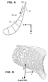
- FIG. 4 and 5 there is shown a Cartesian coordinate system for X, Y and Z values set forth in Tables I and II, which follow.
- the Cartesian coordinate system has orthogonally-related X, Y and Z axes.
- the Z value is not a true radial height. Rather, the dimension is a height from a plane through the horizontal engine centerline.
- the Y axis lies parallel to the machine centerline, i.e., the rotary axis.
- the surface profiles at various surface locations between the radial distance Z are ascertained by connecting adjacent profiles. See, for example, the profiles of Figure 5, which define the airfoil at various heights in the Z direction. These tabular values are given in inches, represent actual airfoil profiles at ambient, non-operating or non-hot conditions and are for an uncoated airfoil. Additionally, the sign convention assigns a positive value to the value Z and positive and negative values for the coordinates X and Y, as typically used in Cartesian coordinate systems. It will be appreciated that during engine operation, the nozzle heats up and the mechanical and thermal loading cause predicted thermal growth and deformation of the X, Y and Z values as defined. Consequently, the nozzle changes shape slightly during operation.
- the cold or ambient temperature profile is set forth in Table I because it is the nozzle casting or fabrication that is required to obtain the desired hot gas path profiles. Further, it will be appreciated that forty-two equally spaced nozzles are arranged in a circumferential array thereof about the engine centerline.
- the coordinate values of X, Y and Z for the airfoils and the inner and outer bands define the hot gas path annulus through the nozzle stage.
- the thermal barrier coating (ceramic coating) on the blade has a current manufacturing tolerance of up to ⁇ .015 inches.
- the thermal barrier coating ceramic coating
- the claimed profile tolerance for the nozzle gas path surface is +.165 to -.135 inches.
- the nozzle includes the formation of the nozzle from a high-strength nickel-based superalloy, multiple internal ribs to withstand pressure loadings and a thermal barrier coating to release thermal load on the metal. Additionally, the leading edge radius is optimized to reduce thermodynamic loading.
- the trailing edge region near the inner side wall, i.e., the inner diameter wall 16, is thickened locally to improve castability of the nozzle, while maintaining stage performance.
- the preferred nozzle has seven closed-circuit cavities 22 ( Figure 4) and one trailing edge air-cooled cavity (26), although it will be appreciated that the present invention can be employed in a nozzle having any one of a number of cavities or none at all.
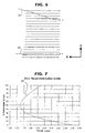
- the minimum throat distance at various distances in the Z direction are given.
- the minimum throat 28 ( Figure 3) is given in inches by line 34 ( Figure 7) as a function of the percent radial span of the vane from the inner wall to the outer wall.
Landscapes
- Engineering & Computer Science (AREA)
- Mechanical Engineering (AREA)
- General Engineering & Computer Science (AREA)
- Physics & Mathematics (AREA)
- Fluid Mechanics (AREA)
- Turbine Rotor Nozzle Sealing (AREA)
- Materials For Photolithography (AREA)
Abstract
Description


Claims (9)
- An airfoil (12) for a gas turbine nozzle stage having a profile at ambient temperature substantially in accordance with Cartesian coordinate values of X, Y and Z set forth in Table I wherein Z is a height from a plane through a horizontal centerline of the turbine and X and Y are coordinate values defining the profile at each distance Z from the plane through the horizontal centerline of the turbine, said values being in inches and having a tolerance of +.165 to -.135.
- An airfoil according to Claim 1 including a thermal barrier coating on said airfoil.
- An airfoil according to Claim 1 wherein said airfoil has a plurality of cavities (22) within the airfoil extending substantially the entire length of the airfoil.
- An airfoil according to Claim 1 having an outer wall (14) and an inner wall (16) defining with said airfoil an airfoil segment.
- An airfoil according to Claim 4 wherein the inner diameter and the outer diameter of the inner and outer walls, respectively, have profiles at ambient temperature substantially in accordance with Cartesian coordinate values of X, Y and Z as set forth in Table II wherein Z is a height from a plane through the horizontal centerline of the turbine and X and Y are coordinate values defining the inner and outer radii of the inner and outer walls at each distance Z from the plane through the horizontal centerline of the turbine, said values of Table II being in inches and having a tolerance of +.165 to -.135.
- A nozzle stage for a gas turbine comprising:forty-two airfoils spaced equally one from the other about a horizontal centerline of the gas turbine, each said airfoil having a profile at ambient temperature substantially in accordance with Cartesian coordinate values of X, Y and Z set forth in Table I wherein Z is a height from a plane through a horizontal centerline of the turbine and X and Y are coordinate values defining the profile at each distance Z from the plane through the horizontal centerline of the turbine, said values being in inches and having a tolerance of +.165 to -.135.
- A nozzle stage according to Claim 6 having outer and inner walls (14, 16) defining an annulus through the nozzle stage.
- A nozzle stage according to Claim 7 wherein the inner diameter and the outer diameter of the inner and outer walls, respectively, have profiles at ambient temperature substantially in accordance with Cartesian coordinate values of X, Y and Z as set forth in Table II wherein Z is a height from a plane through the horizontal centerline of the turbine and X and Y are coordinate values defining radii along inner and outer walls of the annulus at each distance Z from the plane through the horizontal centerline of the turbine, said values being in inches and having a tolerance of +.165 to -.135.
- A nozzle stage according to Claim 7 having a minimum throat (28) between adjacent airfoils according to the graph of Figure 7 illustrating the minimum throat as a function of the percentage of the radial span from the inner wall (16) to the outer wall (14).
Applications Claiming Priority (2)
| Application Number | Priority Date | Filing Date | Title |
|---|---|---|---|
| US779226 | 1985-09-23 | ||
| US09/779,226 US6398489B1 (en) | 2001-02-08 | 2001-02-08 | Airfoil shape for a turbine nozzle |
Publications (2)
| Publication Number | Publication Date |
|---|---|
| EP1231358A2 true EP1231358A2 (en) | 2002-08-14 |
| EP1231358A3 EP1231358A3 (en) | 2004-09-22 |
Family
ID=25115728
Family Applications (1)
| Application Number | Title | Priority Date | Filing Date |
|---|---|---|---|
| EP02250819A Withdrawn EP1231358A3 (en) | 2001-02-08 | 2002-02-07 | Airfoil shape for a turbine nozzle |
Country Status (4)
| Country | Link |
|---|---|
| US (1) | US6398489B1 (en) |
| EP (1) | EP1231358A3 (en) |
| JP (1) | JP2002276303A (en) |
| KR (1) | KR20020066187A (en) |
Cited By (5)
| Publication number | Priority date | Publication date | Assignee | Title |
|---|---|---|---|---|
| RU2342538C2 (en) * | 2003-03-12 | 2008-12-27 | Дженерал Электрик Компани | Turbine blade with aerodynamic profile (versions) and turbine |
| RU2350756C2 (en) * | 2003-07-18 | 2009-03-27 | Дженерал Электрик Компани | Turbine blade aerodynamic profile (versions) and turbine (versions) |
| US7976274B2 (en) | 2005-12-08 | 2011-07-12 | General Electric Company | Methods and apparatus for assembling turbine engines |
| CN103670528A (en) * | 2013-12-20 | 2014-03-26 | 东方电气集团东方汽轮机有限公司 | Loading method for turbine blade |
| US10012086B2 (en) | 2013-11-04 | 2018-07-03 | United Technologies Corporation | Gas turbine engine airfoil profile |
Families Citing this family (136)
| Publication number | Priority date | Publication date | Assignee | Title |
|---|---|---|---|---|
| US6461110B1 (en) * | 2001-07-11 | 2002-10-08 | General Electric Company | First-stage high pressure turbine bucket airfoil |
| US6604285B2 (en) * | 2001-06-07 | 2003-08-12 | General Electric Company | Method and apparatus for electronically determining nozzle throat area and harmonics |
| US6503059B1 (en) | 2001-07-06 | 2003-01-07 | General Electric Company | Fourth-stage turbine bucket airfoil |
| US6503054B1 (en) | 2001-07-13 | 2003-01-07 | General Electric Company | Second-stage turbine nozzle airfoil |
| US6461109B1 (en) * | 2001-07-13 | 2002-10-08 | General Electric Company | Third-stage turbine nozzle airfoil |
| WO2003006797A1 (en) * | 2001-07-13 | 2003-01-23 | General Electric Company | Second-stage turbine nozzle airfoil |
| ITMI20012169A1 (en) * | 2001-10-18 | 2003-04-18 | Nuovo Pignone Spa | STATIC RETURN CHANNEL PALETTING FOR TWO-DIMENSIONAL CENTRIFUGAL STAGES OF A MULTI-STAGE CENTRIFUGAL COMPRESSOR WITH BEST EFFICIENCY |
| US6558122B1 (en) | 2001-11-14 | 2003-05-06 | General Electric Company | Second-stage turbine bucket airfoil |
| GB2384276A (en) * | 2002-01-18 | 2003-07-23 | Alstom | Gas turbine low pressure stage |
| US6685434B1 (en) * | 2002-09-17 | 2004-02-03 | General Electric Company | Second stage turbine bucket airfoil |
| US6939106B2 (en) * | 2002-12-11 | 2005-09-06 | General Electric Company | Sealing of steam turbine nozzle hook leakages using a braided rope seal |
| US6832892B2 (en) | 2002-12-11 | 2004-12-21 | General Electric Company | Sealing of steam turbine bucket hook leakages using a braided rope seal |
| US6887041B2 (en) * | 2003-03-03 | 2005-05-03 | General Electric Company | Airfoil shape for a turbine nozzle |
| US6736599B1 (en) | 2003-05-14 | 2004-05-18 | General Electric Company | First stage turbine nozzle airfoil |
| US6881038B1 (en) * | 2003-10-09 | 2005-04-19 | General Electric Company | Airfoil shape for a turbine bucket |
| US7024744B2 (en) * | 2004-04-01 | 2006-04-11 | General Electric Company | Frequency-tuned compressor stator blade and related method |
| US7001147B1 (en) * | 2004-07-28 | 2006-02-21 | General Electric Company | Airfoil shape and sidewall flowpath surfaces for a turbine nozzle |
| US7094034B2 (en) | 2004-07-30 | 2006-08-22 | United Technologies Corporation | Airfoil profile with optimized aerodynamic shape |
| US7186090B2 (en) * | 2004-08-05 | 2007-03-06 | General Electric Company | Air foil shape for a compressor blade |
| ITMI20041804A1 (en) * | 2004-09-21 | 2004-12-21 | Nuovo Pignone Spa | SHOVEL OF A RUTOR OF A FIRST STAGE OF A GAS TURBINE |
| US20060216144A1 (en) * | 2005-03-28 | 2006-09-28 | Sullivan Michael A | First and second stage turbine airfoil shapes |
| US20070050172A1 (en) * | 2005-09-01 | 2007-03-01 | General Electric Company | Method and apparatus for measuring throat areas of gas turbine engine nozzle assemblies |
| GB2445897B (en) * | 2005-12-29 | 2011-06-08 | Rolls Royce Power Eng | Airfoil for a first stage nozzle guide vane |
| CA2634738C (en) * | 2005-12-29 | 2013-03-26 | Rolls-Royce Power Engineering Plc | Second stage turbine airfoil |
| WO2007085912A2 (en) * | 2005-12-29 | 2007-08-02 | Rolls-Royce Power Engineering Plc | Airfoil for a first stage nozzle guide vane |
| CA2633319C (en) * | 2005-12-29 | 2013-02-19 | Rolls-Royce Power Engineering Plc | First stage turbine airfoil |
| US7632072B2 (en) * | 2005-12-29 | 2009-12-15 | Rolls-Royce Power Engineering Plc | Third stage turbine airfoil |
| US7722329B2 (en) * | 2005-12-29 | 2010-05-25 | Rolls-Royce Power Engineering Plc | Airfoil for a third stage nozzle guide vane |
| US7648334B2 (en) * | 2005-12-29 | 2010-01-19 | Rolls-Royce Power Engineering Plc | Airfoil for a second stage nozzle guide vane |
| US7329093B2 (en) * | 2006-01-27 | 2008-02-12 | General Electric Company | Nozzle blade airfoil profile for a turbine |
| US7329092B2 (en) * | 2006-01-27 | 2008-02-12 | General Electric Company | Stator blade airfoil profile for a compressor |
| US7306436B2 (en) * | 2006-03-02 | 2007-12-11 | Pratt & Whitney Canada Corp. | HP turbine blade airfoil profile |
| US7402026B2 (en) * | 2006-03-02 | 2008-07-22 | Pratt & Whitney Canada Corp. | Turbine exhaust strut airfoil profile |
| US7367779B2 (en) * | 2006-03-02 | 2008-05-06 | Pratt & Whitney Canada Corp. | LP turbine vane airfoil profile |
| US7354249B2 (en) * | 2006-03-02 | 2008-04-08 | Pratt & Whitney Canada Corp. | LP turbine blade airfoil profile |
| US7351038B2 (en) * | 2006-03-02 | 2008-04-01 | Pratt & Whitney Canada Corp. | HP turbine vane airfoil profile |
| US7396211B2 (en) * | 2006-03-30 | 2008-07-08 | General Electric Company | Stator blade airfoil profile for a compressor |
| US7467926B2 (en) * | 2006-06-09 | 2008-12-23 | General Electric Company | Stator blade airfoil profile for a compressor |
| US7581930B2 (en) * | 2006-08-16 | 2009-09-01 | United Technologies Corporation | High lift transonic turbine blade |
| US7625182B2 (en) * | 2006-09-05 | 2009-12-01 | Pratt & Whitney Canada Corp. | Turbine exhaust strut airfoil and gas path profile |
| US7534091B2 (en) * | 2006-09-05 | 2009-05-19 | Pratt & Whitney Canada Corp. | HP turbine blade airfoil profile |
| US7537433B2 (en) * | 2006-09-05 | 2009-05-26 | Pratt & Whitney Canada Corp. | LP turbine blade airfoil profile |
| US7625183B2 (en) * | 2006-09-05 | 2009-12-01 | Pratt & Whitney Canada Corp. | LP turbine van airfoil profile |
| US7537432B2 (en) * | 2006-09-05 | 2009-05-26 | Pratt & Whitney Canada Corp. | HP turbine vane airfoil profile |
| US7611326B2 (en) * | 2006-09-06 | 2009-11-03 | Pratt & Whitney Canada Corp. | HP turbine vane airfoil profile |
| US7520728B2 (en) * | 2006-09-07 | 2009-04-21 | Pratt & Whitney Canada Corp. | HP turbine vane airfoil profile |
| US7520726B2 (en) * | 2006-09-07 | 2009-04-21 | Pratt & Whitney Canada Corp. | HP turbine blade airfoil profile |
| US7520727B2 (en) * | 2006-09-07 | 2009-04-21 | Pratt & Whitney Canada Corp. | HP turbine blade airfoil profile |
| US7510378B2 (en) * | 2006-10-25 | 2009-03-31 | General Electric Company | Airfoil shape for a compressor |
| US7517197B2 (en) * | 2006-10-25 | 2009-04-14 | General Electric Company | Airfoil shape for a compressor |
| US7513748B2 (en) * | 2006-10-25 | 2009-04-07 | General Electric Company | Airfoil shape for a compressor |
| US7572104B2 (en) * | 2006-10-25 | 2009-08-11 | General Electric Company | Airfoil shape for a compressor |
| US7566202B2 (en) * | 2006-10-25 | 2009-07-28 | General Electric Company | Airfoil shape for a compressor |
| US7572105B2 (en) * | 2006-10-25 | 2009-08-11 | General Electric Company | Airfoil shape for a compressor |
| US7527473B2 (en) * | 2006-10-26 | 2009-05-05 | General Electric Company | Airfoil shape for a turbine nozzle |
| US7497663B2 (en) * | 2006-10-26 | 2009-03-03 | General Electric Company | Rotor blade profile optimization |
| US7497665B2 (en) * | 2006-11-02 | 2009-03-03 | General Electric Company | Airfoil shape for a compressor |
| US7568892B2 (en) * | 2006-11-02 | 2009-08-04 | General Electric Company | Airfoil shape for a compressor |
| US7559747B2 (en) * | 2006-11-22 | 2009-07-14 | Pratt & Whitney Canada Corp. | Turbine exhaust strut airfoil profile |
| US7568890B2 (en) * | 2006-11-22 | 2009-08-04 | Pratt & Whitney Canada Corp. | LP turbine vane airfoil profile |
| US7568889B2 (en) * | 2006-11-22 | 2009-08-04 | Pratt & Whitney Canada Corp. | HP turbine blade airfoil profile |
| US7559746B2 (en) * | 2006-11-22 | 2009-07-14 | Pratt & Whitney Canada Corp. | LP turbine blade airfoil profile |
| US7568891B2 (en) * | 2006-11-22 | 2009-08-04 | Pratt & Whitney Canada Corp. | HP turbine vane airfoil profile |
| US7854695B2 (en) * | 2006-11-24 | 2010-12-21 | Clinical Technology (Nz), Ltd. | Exercise and therapeutic apparatus |
| US7857594B2 (en) * | 2006-11-28 | 2010-12-28 | Pratt & Whitney Canada Corp. | Turbine exhaust strut airfoil profile |
| US7559748B2 (en) * | 2006-11-28 | 2009-07-14 | Pratt & Whitney Canada Corp. | LP turbine blade airfoil profile |
| US7566200B2 (en) * | 2006-11-28 | 2009-07-28 | Pratt & Whitney Canada Corp. | HP turbine vane airfoil profile |
| US7559749B2 (en) * | 2006-11-28 | 2009-07-14 | Pratt & Whitney Canada Corp. | LP turbine vane airfoil profile |
| US7632074B2 (en) * | 2006-11-28 | 2009-12-15 | Pratt & Whitney Canada Corp. | HP turbine blade airfoil profile |
| US8457084B2 (en) * | 2006-12-20 | 2013-06-04 | Airvana Llc | Communication group configuration in a network |
| JP4665916B2 (en) * | 2007-02-28 | 2011-04-06 | 株式会社日立製作所 | First stage rotor blade of gas turbine |
| JP4659008B2 (en) * | 2007-09-13 | 2011-03-30 | ルネサスエレクトロニクス株式会社 | Peripheral circuit with host load adjustment function |
| US7862303B2 (en) | 2007-10-12 | 2011-01-04 | Pratt & Whitney Canada Corp. | Compressor turbine vane airfoil profile |
| US7862304B2 (en) * | 2007-10-12 | 2011-01-04 | Pratt & Whitney Canada Corp. | Compressor turbine blade airfoil profile |
| US8038411B2 (en) * | 2008-07-14 | 2011-10-18 | Pratt & Whitney Canada Corp. | Compressor turbine blade airfoil profile |
| EP2379276A4 (en) * | 2008-12-19 | 2012-06-27 | Volvo Aero Corp | Spoke for a stator component, stator component and method for manufacturing a stator component |
| US8100659B2 (en) * | 2009-04-17 | 2012-01-24 | Pratt & Whitney Canada Corp. | HP turbine vane airfoil profile |
| GB2471152B (en) * | 2009-06-17 | 2016-08-10 | Dresser-Rand Company | Use of bowed nozzle vanes to reduce acoustic signature |
| US8105043B2 (en) * | 2009-06-30 | 2012-01-31 | Pratt & Whitney Canada Corp. | HP turbine blade airfoil profile |
| US8573945B2 (en) * | 2009-11-13 | 2013-11-05 | Alstom Technology Ltd. | Compressor stator vane |
| US9291059B2 (en) | 2009-12-23 | 2016-03-22 | Alstom Technology Ltd. | Airfoil for a compressor blade |
| US8523531B2 (en) * | 2009-12-23 | 2013-09-03 | Alstom Technology Ltd | Airfoil for a compressor blade |
| CA2728968C (en) * | 2010-01-21 | 2014-05-27 | Pratt & Whitney Canada Corp. | Hp turbine vane airfoil profile |
| US8167568B2 (en) * | 2010-03-26 | 2012-05-01 | Pratt & Whitney Canada Corp. | High pressure turbine blade airfoil profile |
| US8511979B2 (en) | 2010-03-30 | 2013-08-20 | Pratt & Whitney Canada Corp. | High pressure turbine vane airfoil profile |
| US8439645B2 (en) | 2010-03-30 | 2013-05-14 | Pratt & Whitney Canada Corp. | High pressure turbine blade airfoil profile |
| US8105044B2 (en) | 2010-04-23 | 2012-01-31 | Pratt & Whitney Canada Corp. | Compressor turbine blade airfoil profile |
| US8568085B2 (en) * | 2010-07-19 | 2013-10-29 | Pratt & Whitney Canada Corp | High pressure turbine vane cooling hole distrubution |
| US8602727B2 (en) | 2010-07-22 | 2013-12-10 | General Electric Company | Turbine nozzle segment having arcuate concave leading edge |
| US8734113B2 (en) * | 2010-07-26 | 2014-05-27 | Snecma | Optimized aerodynamic profile for a turbine vane, in particular for a nozzle of the fourth stage of a turbine |
| US8393870B2 (en) | 2010-09-08 | 2013-03-12 | United Technologies Corporation | Turbine blade airfoil |
| US8602740B2 (en) | 2010-09-08 | 2013-12-10 | United Technologies Corporation | Turbine vane airfoil |
| KR101232056B1 (en) * | 2010-12-21 | 2013-02-12 | 두산중공업 주식회사 | Nozzle Blade for a Gas Turbine |
| US8591193B2 (en) | 2011-02-25 | 2013-11-26 | General Electric Company | Airfoil shape for a compressor blade |
| US8864456B2 (en) | 2011-09-19 | 2014-10-21 | Hamilton Sundstrand Corporation | Turbine nozzle for air cycle machine |
| ITTO20111009A1 (en) | 2011-11-03 | 2013-05-04 | Avio Spa | AERODYNAMIC PROFILE OF A TURBINE |
| US8827641B2 (en) * | 2011-11-28 | 2014-09-09 | General Electric Company | Turbine nozzle airfoil profile |
| US8944750B2 (en) | 2011-12-22 | 2015-02-03 | Pratt & Whitney Canada Corp. | High pressure turbine vane cooling hole distribution |
| US8979487B2 (en) | 2012-04-11 | 2015-03-17 | Pratt & Whitney Canada Corp. | High pressure turbine vane airfoil profile |
| US9322279B2 (en) | 2012-07-02 | 2016-04-26 | United Technologies Corporation | Airfoil cooling arrangement |
| US8707712B2 (en) | 2012-07-02 | 2014-04-29 | United Technologies Corporation | Gas turbine engine turbine vane airfoil profile |
| US9109453B2 (en) | 2012-07-02 | 2015-08-18 | United Technologies Corporation | Airfoil cooling arrangement |
| US9121289B2 (en) | 2012-09-28 | 2015-09-01 | Pratt & Whitney Canada Corp. | High pressure turbine blade cooling hole distribution |
| US9062556B2 (en) | 2012-09-28 | 2015-06-23 | Pratt & Whitney Canada Corp. | High pressure turbine blade cooling hole distribution |
| US10072512B2 (en) * | 2013-04-24 | 2018-09-11 | Hamilton Sundstrand Corporation | Turbine nozzle and shroud |
| US9458723B2 (en) | 2014-02-28 | 2016-10-04 | Pratt & Whitney Canada Corp. | Power turbine blade airfoil profile |
| US9581029B2 (en) | 2014-09-24 | 2017-02-28 | Pratt & Whitney Canada Corp. | High pressure turbine blade cooling hole distribution |
| US9470093B2 (en) * | 2015-03-18 | 2016-10-18 | United Technologies Corporation | Turbofan arrangement with blade channel variations |
| JP6971564B2 (en) * | 2015-12-18 | 2021-11-24 | ゼネラル・エレクトリック・カンパニイ | Turbomachinery and turbine nozzles for it |
| US9963985B2 (en) * | 2015-12-18 | 2018-05-08 | General Electric Company | Turbomachine and turbine nozzle therefor |
| US10443392B2 (en) * | 2016-07-13 | 2019-10-15 | Safran Aircraft Engines | Optimized aerodynamic profile for a turbine vane, in particular for a nozzle of the second stage of a turbine |
| US10443393B2 (en) * | 2016-07-13 | 2019-10-15 | Safran Aircraft Engines | Optimized aerodynamic profile for a turbine vane, in particular for a nozzle of the seventh stage of a turbine |
| US10087952B2 (en) * | 2016-09-23 | 2018-10-02 | General Electric Company | Airfoil shape for first stage compressor stator vane |
| US10876417B2 (en) * | 2017-08-17 | 2020-12-29 | Raytheon Technologies Corporation | Tuned airfoil assembly |
| US10487661B2 (en) * | 2017-08-31 | 2019-11-26 | Pratt & Whitney Canada Corp. | Power turbine vane airfoil profile |
| US10598034B2 (en) | 2017-08-31 | 2020-03-24 | Pratt & Whitney Canada Corp. | Power turbine vane airfoil profile |
| US10513929B2 (en) | 2017-08-31 | 2019-12-24 | Pratt & Whitney Canada Corp. | Compressor turbine blade airfoil profile |
| US10329915B2 (en) * | 2017-09-01 | 2019-06-25 | Pratt & Whitney Canada Corp. | Power turbine blade airfoil profile |
| US10480335B2 (en) | 2017-09-01 | 2019-11-19 | Pratt & Whitney Canada Corp. | Compressor turbine vane airfoil profile |
| US10598023B2 (en) | 2017-09-01 | 2020-03-24 | Pratt & Whitney Canada Corp. | Power turbine blade airfoil profile |
| US10287889B2 (en) | 2017-09-26 | 2019-05-14 | Pratt & Whitney Canada Corp. | Power turbine vane airfoil profile |
| US11015450B2 (en) | 2019-06-14 | 2021-05-25 | Pratt & Whitney Canada Corp. | High pressure turbine blade airfoil profile |
| US11015459B2 (en) | 2019-10-10 | 2021-05-25 | Power Systems Mfg., Llc | Additive manufacturing optimized first stage vane |
| US11578602B1 (en) | 2021-10-14 | 2023-02-14 | Pratt & Whitney Canada Corp. | Turbine blade airfoil profile |
| US11578600B1 (en) | 2021-10-15 | 2023-02-14 | Pratt & Whitney Canada Corp. | Turbine blade airfoil profile |
| US11591921B1 (en) | 2021-11-05 | 2023-02-28 | Rolls-Royce Plc | Ceramic matrix composite vane assembly |
| US11572790B1 (en) | 2021-11-11 | 2023-02-07 | Pratt & Whitney Canada Corp. | Turbine blade airfoil profile |
| US11578608B1 (en) | 2021-11-11 | 2023-02-14 | Pratt & Whitney Canada Corp. | Turbine vane airfoil profile |
| US11572789B1 (en) | 2021-11-11 | 2023-02-07 | Pratt & Whitney Canada Corp. | Turbine blade airfoil profile |
| US11578601B1 (en) | 2021-11-12 | 2023-02-14 | Pratt & Whitney Canada Corp. | Turbine blade airfoil profile |
| US11603763B1 (en) | 2021-11-12 | 2023-03-14 | Pratt & Whitney Canada Corp. | Turbine blade airfoil profile |
| US11713679B1 (en) * | 2022-01-27 | 2023-08-01 | Raytheon Technologies Corporation | Tangentially bowed airfoil |
| US11536141B1 (en) | 2022-02-04 | 2022-12-27 | Pratt & Whitney Canada Corp. | Turbine vane airfoil profile |
| US11512595B1 (en) | 2022-02-04 | 2022-11-29 | Pratt & Whitney Canada Corp. | Turbine blade airfoil profile |
| US11867081B1 (en) | 2023-01-26 | 2024-01-09 | Pratt & Whitney Canada Corp. | Turbine blade airfoil profile |
| US11913359B1 (en) * | 2023-06-30 | 2024-02-27 | Ge Infrastructure Technology Llc | Nozzle airfoil profile with elliptical trailing edge |
Family Cites Families (13)
| Publication number | Priority date | Publication date | Assignee | Title |
|---|---|---|---|---|
| JPS57119103A (en) * | 1981-01-14 | 1982-07-24 | Toshiba Corp | Axial flow turbine |
| US4585395A (en) * | 1983-12-12 | 1986-04-29 | General Electric Company | Gas turbine engine blade |
| US5174715A (en) * | 1990-12-13 | 1992-12-29 | General Electric Company | Turbine nozzle |
| US5299915A (en) | 1992-07-15 | 1994-04-05 | General Electric Corporation | Bucket for the last stage of a steam turbine |
| US5267834A (en) | 1992-12-30 | 1993-12-07 | General Electric Company | Bucket for the last stage of a steam turbine |
| JPH07253001A (en) * | 1994-03-16 | 1995-10-03 | Mitsubishi Heavy Ind Ltd | Integral shroud moving blade |
| JP3621216B2 (en) * | 1996-12-05 | 2005-02-16 | 株式会社東芝 | Turbine nozzle |
| JPH10184304A (en) * | 1996-12-27 | 1998-07-14 | Toshiba Corp | Axial turbine turbine nozzles and turbine blades |
| US5980209A (en) | 1997-06-27 | 1999-11-09 | General Electric Co. | Turbine blade with enhanced cooling and profile optimization |
| JPH11311103A (en) * | 1998-04-27 | 1999-11-09 | Toshiba Corp | High-temperature components, high-temperature components for gas turbines, and methods for producing them |
| DE69921320T2 (en) * | 1998-06-12 | 2005-10-27 | Ebara Corp. | TURBINENSTATORSCHAUFEL |
| US6077036A (en) | 1998-08-20 | 2000-06-20 | General Electric Company | Bowed nozzle vane with selective TBC |
| US6325593B1 (en) * | 2000-02-18 | 2001-12-04 | General Electric Company | Ceramic turbine airfoils with cooled trailing edge blocks |
-
2001
- 2001-02-08 US US09/779,226 patent/US6398489B1/en not_active Expired - Fee Related
-
2002
- 2002-02-06 KR KR1020020006871A patent/KR20020066187A/en not_active Withdrawn
- 2002-02-06 JP JP2002028870A patent/JP2002276303A/en active Pending
- 2002-02-07 EP EP02250819A patent/EP1231358A3/en not_active Withdrawn
Cited By (5)
| Publication number | Priority date | Publication date | Assignee | Title |
|---|---|---|---|---|
| RU2342538C2 (en) * | 2003-03-12 | 2008-12-27 | Дженерал Электрик Компани | Turbine blade with aerodynamic profile (versions) and turbine |
| RU2350756C2 (en) * | 2003-07-18 | 2009-03-27 | Дженерал Электрик Компани | Turbine blade aerodynamic profile (versions) and turbine (versions) |
| US7976274B2 (en) | 2005-12-08 | 2011-07-12 | General Electric Company | Methods and apparatus for assembling turbine engines |
| US10012086B2 (en) | 2013-11-04 | 2018-07-03 | United Technologies Corporation | Gas turbine engine airfoil profile |
| CN103670528A (en) * | 2013-12-20 | 2014-03-26 | 东方电气集团东方汽轮机有限公司 | Loading method for turbine blade |
Also Published As
| Publication number | Publication date |
|---|---|
| KR20020066187A (en) | 2002-08-14 |
| US6398489B1 (en) | 2002-06-04 |
| JP2002276303A (en) | 2002-09-25 |
| EP1231358A3 (en) | 2004-09-22 |
Similar Documents
| Publication | Publication Date | Title |
|---|---|---|
| EP1231358A2 (en) | Airfoil shape for a turbine nozzle | |
| CN100472033C (en) | Turbine rotor blades for gas turbine engines | |
| JP4570135B2 (en) | Cooling hole position, configuration and configuration of peripheral cooling turbine bucket airfoil | |
| US7384243B2 (en) | Stator vane profile optimization | |
| US6769878B1 (en) | Turbine blade airfoil | |
| US6419446B1 (en) | Apparatus and method for inhibiting radial transfer of core gas flow within a core gas flow path of a gas turbine engine | |
| EP1319803B1 (en) | Coolable rotor blade for an industrial gas turbine engine | |
| JP4785507B2 (en) | Turbine nozzle with bull nose step | |
| EP1079071B1 (en) | Turbine blade with preferentially cooled trailing edge pressure wall | |
| JP4311919B2 (en) | Turbine airfoils for gas turbine engines | |
| US6997679B2 (en) | Airfoil cooling holes | |
| US8052395B2 (en) | Air cooled bucket for a turbine | |
| US7766606B2 (en) | Turbine airfoil cooling system with platform cooling channels with diffusion slots | |
| JP2005076639A (en) | Cooling hole position, configuration and configuration of turbine bucket airfoil | |
| US20040081548A1 (en) | Flow directing device | |
| EP1253291A1 (en) | A turbine blade having a cooled tip shroud | |
| US20080273970A1 (en) | HP turbine vane airfoil profile | |
| JP4665916B2 (en) | First stage rotor blade of gas turbine | |
| KR20040018453A (en) | Second-stage turbine nozzle airfoil | |
| JP2005113920A (en) | Airfoil shape for turbine bucket | |
| JP2004534920A (en) | First stage high pressure turbine bucket airfoil | |
| JP2004353676A (en) | Airfoil shape for turbine bucket | |
| JP2004108369A (en) | First stage turbine bucket airfoil | |
| US10364683B2 (en) | Gas turbine engine component cooling passage turbulator | |
| JP2003106101A (en) | Turbine airfoil for gas turbine engines |
Legal Events
| Date | Code | Title | Description |
|---|---|---|---|
| PUAI | Public reference made under article 153(3) epc to a published international application that has entered the european phase |
Free format text: ORIGINAL CODE: 0009012 |
|
| AK | Designated contracting states |
Kind code of ref document: A2 Designated state(s): AT BE CH CY DE DK ES FI FR GB GR IE IT LI LU MC NL PT SE TR |
|
| AX | Request for extension of the european patent |
Free format text: AL;LT;LV;MK;RO;SI |
|
| PUAL | Search report despatched |
Free format text: ORIGINAL CODE: 0009013 |
|
| AK | Designated contracting states |
Kind code of ref document: A3 Designated state(s): AT BE CH CY DE DK ES FI FR GB GR IE IT LI LU MC NL PT SE TR |
|
| AX | Request for extension of the european patent |
Extension state: AL LT LV MK RO SI |
|
| 17P | Request for examination filed |
Effective date: 20050322 |
|
| AKX | Designation fees paid |
Designated state(s): AT BE CH CY DE DK ES FI FR GB GR IE IT LI LU MC NL PT SE TR |
|
| 17Q | First examination report despatched |
Effective date: 20061228 |
|
| STAA | Information on the status of an ep patent application or granted ep patent |
Free format text: STATUS: THE APPLICATION IS DEEMED TO BE WITHDRAWN |
|
| 18D | Application deemed to be withdrawn |
Effective date: 20100515 |