RU2350756C2 - Turbine blade aerodynamic profile (versions) and turbine (versions) - Google Patents

Turbine blade aerodynamic profile (versions) and turbine (versions) Download PDF

Info

Publication number
RU2350756C2
RU2350756C2 RU2004121998/06A RU2004121998A RU2350756C2 RU 2350756 C2 RU2350756 C2 RU 2350756C2 RU 2004121998/06 A RU2004121998/06 A RU 2004121998/06A RU 2004121998 A RU2004121998 A RU 2004121998A RU 2350756 C2 RU2350756 C2 RU 2350756C2
Authority
RU
Russia
Prior art keywords
blade
turbine
inches
values
distances
Prior art date
Application number
RU2004121998/06A
Other languages
Russian (ru)
Other versions
RU2004121998A (en
Inventor
Сузан Мари ХАЙД (US)
Сузан Мари ХАЙД
Роберт Романи БАЙ (US)
Роберт Романи БАЙ
Джон Конрад ШЕФФЕР (US)
Джон Конрад ШЕФФЕР
Калвин Леви СИМС (US)
Калвин Леви СИМС
Майкл Эрнест БОЙСКЛЭР (US)
Майкл Эрнест БОЙСКЛЭР
Original Assignee
Дженерал Электрик Компани
Priority date (The priority date is an assumption and is not a legal conclusion. Google has not performed a legal analysis and makes no representation as to the accuracy of the date listed.)
Filing date
Publication date
Application filed by Дженерал Электрик Компани filed Critical Дженерал Электрик Компани
Publication of RU2004121998A publication Critical patent/RU2004121998A/en
Application granted granted Critical
Publication of RU2350756C2 publication Critical patent/RU2350756C2/en

Links

Images

Classifications

    • FMECHANICAL ENGINEERING; LIGHTING; HEATING; WEAPONS; BLASTING
    • F01MACHINES OR ENGINES IN GENERAL; ENGINE PLANTS IN GENERAL; STEAM ENGINES
    • F01DNON-POSITIVE DISPLACEMENT MACHINES OR ENGINES, e.g. STEAM TURBINES
    • F01D5/00Blades; Blade-carrying members; Heating, heat-insulating, cooling or antivibration means on the blades or the members
    • F01D5/12Blades
    • F01D5/14Form or construction
    • F01D5/18Hollow blades, i.e. blades with cooling or heating channels or cavities; Heating, heat-insulating or cooling means on blades
    • FMECHANICAL ENGINEERING; LIGHTING; HEATING; WEAPONS; BLASTING
    • F01MACHINES OR ENGINES IN GENERAL; ENGINE PLANTS IN GENERAL; STEAM ENGINES
    • F01DNON-POSITIVE DISPLACEMENT MACHINES OR ENGINES, e.g. STEAM TURBINES
    • F01D5/00Blades; Blade-carrying members; Heating, heat-insulating, cooling or antivibration means on the blades or the members
    • F01D5/12Blades
    • F01D5/14Form or construction
    • F01D5/141Shape, i.e. outer, aerodynamic form
    • FMECHANICAL ENGINEERING; LIGHTING; HEATING; WEAPONS; BLASTING
    • F01MACHINES OR ENGINES IN GENERAL; ENGINE PLANTS IN GENERAL; STEAM ENGINES
    • F01DNON-POSITIVE DISPLACEMENT MACHINES OR ENGINES, e.g. STEAM TURBINES
    • F01D5/00Blades; Blade-carrying members; Heating, heat-insulating, cooling or antivibration means on the blades or the members
    • FMECHANICAL ENGINEERING; LIGHTING; HEATING; WEAPONS; BLASTING
    • F05INDEXING SCHEMES RELATING TO ENGINES OR PUMPS IN VARIOUS SUBCLASSES OF CLASSES F01-F04
    • F05DINDEXING SCHEME FOR ASPECTS RELATING TO NON-POSITIVE-DISPLACEMENT MACHINES OR ENGINES, GAS-TURBINES OR JET-PROPULSION PLANTS
    • F05D2250/00Geometry
    • YGENERAL TAGGING OF NEW TECHNOLOGICAL DEVELOPMENTS; GENERAL TAGGING OF CROSS-SECTIONAL TECHNOLOGIES SPANNING OVER SEVERAL SECTIONS OF THE IPC; TECHNICAL SUBJECTS COVERED BY FORMER USPC CROSS-REFERENCE ART COLLECTIONS [XRACs] AND DIGESTS
    • Y10TECHNICAL SUBJECTS COVERED BY FORMER USPC
    • Y10STECHNICAL SUBJECTS COVERED BY FORMER USPC CROSS-REFERENCE ART COLLECTIONS [XRACs] AND DIGESTS
    • Y10S416/00Fluid reaction surfaces, i.e. impellers
    • Y10S416/02Formulas of curves

Landscapes

  • Engineering & Computer Science (AREA)
  • Mechanical Engineering (AREA)
  • General Engineering & Computer Science (AREA)
  • Physics & Mathematics (AREA)
  • Fluid Mechanics (AREA)
  • Turbine Rotor Nozzle Sealing (AREA)
  • Developing Agents For Electrophotography (AREA)

Abstract

FIELD: engines and pumps.
SUBSTANCE: turbine incorporates wheel rotor with multiple blades each comprising aerodynamic profile vane with designed profile corresponding, in fact, to values of Cartesian axials X, Y and Z listed in the table enclosed with the application materials. Z values are dimensionless quantities in the range of 0 to 1 transformed in distances Z expressed in inches by multiplying Z values by the vane height in inches. X and Y are distances in inches that, when conjugated by smooth continuous arcs, define the vane profile cross section at each Z distance. The profile cross sections at Z distances, when smoothly conjugated, form the vane complete shape.
EFFECT: higher turbine efficiency.
20 cl, 9 dwg

Description

Текст описания приведен в факсимильном виде.

Figure 00000001
Figure 00000002
Figure 00000003
Figure 00000004
Figure 00000005
Figure 00000006
Figure 00000007
Figure 00000008
Figure 00000009
Figure 00000010
Figure 00000011
Figure 00000012
Figure 00000013
Figure 00000014
Figure 00000015
Figure 00000016
Figure 00000017
Figure 00000018
Figure 00000019
Figure 00000020
Figure 00000021
Figure 00000022
Figure 00000023
Figure 00000024
Figure 00000025
Figure 00000026
Figure 00000027
Figure 00000028
Figure 00000029
Figure 00000030
Figure 00000031
Figure 00000032
Figure 00000033
Figure 00000034
Figure 00000035
Figure 00000036
Figure 00000037
Figure 00000038
Figure 00000039
Figure 00000040
Figure 00000041
Figure 00000042
Figure 00000043
Figure 00000044
Figure 00000045
Figure 00000046
Figure 00000047
Figure 00000048
Figure 00000049
Figure 00000050
Figure 00000051
Figure 00000052
Figure 00000053
Figure 00000054
Figure 00000055
Figure 00000056
Figure 00000057
Figure 00000058
Figure 00000059
Figure 00000060
Figure 00000061
Figure 00000062
The text of the description is given in facsimile form.
Figure 00000001
Figure 00000002
Figure 00000003
Figure 00000004
Figure 00000005
Figure 00000006
Figure 00000007
Figure 00000008
Figure 00000009
Figure 00000010
Figure 00000011
Figure 00000012
Figure 00000013
Figure 00000014
Figure 00000015
Figure 00000016
Figure 00000017
Figure 00000018
Figure 00000019
Figure 00000020
Figure 00000021
Figure 00000022
Figure 00000023
Figure 00000024
Figure 00000025
Figure 00000026
Figure 00000027
Figure 00000028
Figure 00000029
Figure 00000030
Figure 00000031
Figure 00000032
Figure 00000033
Figure 00000034
Figure 00000035
Figure 00000036
Figure 00000037
Figure 00000038
Figure 00000039
Figure 00000040
Figure 00000041
Figure 00000042
Figure 00000043
Figure 00000044
Figure 00000045
Figure 00000046
Figure 00000047
Figure 00000048
Figure 00000049
Figure 00000050
Figure 00000051
Figure 00000052
Figure 00000053
Figure 00000054
Figure 00000055
Figure 00000056
Figure 00000057
Figure 00000058
Figure 00000059
Figure 00000060
Figure 00000061
Figure 00000062

Claims (20)

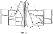
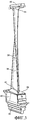
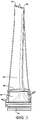
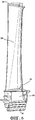
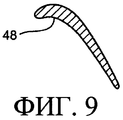
1. Турбинная лопатка (28), включающая в себя лопасть (36) лопатки, имеющую расчетный аэродинамический профиль, по существу соответствующий значениям декартовых координат X, Y и Z, приведенным в Таблице 1, где величины Z являются безразмерными в диапазоне от 0 до 1, преобразуемые в расстояния Z в дюймах путем умножения значений Z на высоту лопасти в дюймах, и где Х и Y являются расстояниями в дюймах, которые при плавном соединении непрерывными дугами определяют сечения (48) профиля лопасти на каждом расстоянии Z, причем сечения профиля на расстояниях Z, будучи соединены плавно друг с другом, образуют завершенную форму лопасти.1. A turbine blade (28), comprising a blade (36) of a blade having a calculated aerodynamic profile essentially corresponding to the Cartesian coordinates X, Y and Z shown in Table 1, where the Z values are dimensionless in the range from 0 to 1 converted to Z distances in inches by multiplying Z values by the height of the blade in inches, and where X and Y are the distances in inches, which, when smoothly connected by continuous arcs, define the sections (48) of the blade profile at each distance Z, and the profile sections at distances Z, b Duchi joined smoothly with one another to form a complete shape of the blade. 2. Турбинная лопатка по п.1, входящая в состав четвертой ступени турбины.2. The turbine blade according to claim 1, which is part of the fourth stage of the turbine. 3. Турбинная лопатка по п.1, в которой упомянутая форма лопасти находится в пределах допуска +0,381 см (0,150 дюйма) в направлении, перпендикулярном поверхности лопасти в любой ее точке.3. The turbine blade according to claim 1, wherein said blade shape is within a tolerance of +0.381 cm (0.150 in) in a direction perpendicular to the surface of the blade at any point thereof. 
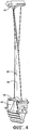
4. Турбинная лопатка по п.1, в которой высота лопасти лопатки при значениях от Z=0 до Z=1,0 составляет 56,416 см (22,211 дюйма).4. The turbine blade according to claim 1, in which the height of the blade of the blade with values from Z = 0 to Z = 1.0 is 56.416 cm (22.211 inches). 5. Турбинная лопатка (28), включающая в себя лопасть (36) лопатки, имеющую расчетный аэродинамический профиль без покрытия, по существу соответствующий значениям декартовых координат X, Y и Z, приведенным в Таблице 1, где величины Z являются безразмерными в диапазоне от 0 до 1, преобразуемые в расстояния Z в дюймах путем умножения значений Z на высоту лопасти в дюймах, и где Х и Y являются расстояниями в дюймах, которые, при соединении плавными непрерывными дугами, определяют сечения (48) профиля лопасти на каждом расстоянии Z, причем сечения профиля на расстояниях Z при плавном соединении друг с другом образуют завершенную форму лопасти, причем значения Х и Y являются масштабируемыми, являясь функцией от одной и той же константы или числа для обеспечения увеличения или уменьшения лопасти.5. A turbine blade (28), comprising a blade (36) of a blade having a calculated aerodynamic profile without coating, essentially corresponding to the Cartesian coordinates X, Y and Z shown in Table 1, where the Z values are dimensionless in the range from 0 to 1, converted to distances Z in inches by multiplying the Z values by the height of the blade in inches, and where X and Y are the distances in inches, which, when connected by smooth continuous arcs, define the sections (48) of the blade profile at each distance Z, and profile sections on The distance Z with smooth conjunction with one another to form a complete shape of the blade, wherein the values of X and Y are scalable, being a function of the same constant or number to provide a increase or decrease of the blade. 6. Турбинная лопатка по п.5, входящая в состав четвертой ступени турбины.6. The turbine blade according to claim 5, which is part of the fourth stage of the turbine. 7. Турбинная лопатка по п.5, в которой упомянутая форма лопасти находится в пределах допуска +0,381 см (0,150 дюйма) в направлении, перпендикулярном поверхности лопасти в любой ее точке.7. The turbine blade of claim 5, wherein said blade shape is within a tolerance of +0.381 cm (0.150 in) in a direction perpendicular to the surface of the blade at any point thereof. 8. Турбинная лопатка по п.5, в которой высота лопасти лопатки при значениях от Z=0 до Z=1,0 составляет 56,416 см (22,211 дюйма).8. The turbine blade according to claim 5, in which the height of the blade of the blade with values from Z = 0 to Z = 1.0 is 56.416 cm (22.211 inches). 
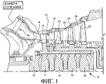
9. Турбина (12), содержащая рабочее колесо (29), имеющее множество лопаток (28), причем каждая из вышеупомянутых лопаток включает в себя лопасть (36), имеющую форму аэродинамического профиля, упомянутая лопасть имеет расчетный профиль, по существу соответствующий значениям декартовых координат X, Y и Z, приведенным в Таблице 1, где величины Z являются безразмерными в диапазоне от 0 до 1, преобразуемые в расстояния Z в дюймах путем умножения значений Z на высоту лопасти в дюймах, и где Х и Y являются расстояниями в дюймах, которые при соединении плавными непрерывными дугами определяют сечения (48) профиля лопасти на каждом расстоянии Z, причем сечения профиля на расстояниях Z при соединении плавно друг с другом образуют завершенную форму лопасти.9. A turbine (12) comprising an impeller (29) having a plurality of blades (28), each of the aforementioned blades including a blade (36) having the shape of an aerodynamic profile, said blade having a design profile substantially corresponding to the Cartesian values the X, Y and Z coordinates shown in Table 1, where Z values are dimensionless in the range from 0 to 1, converted to Z distances in inches by multiplying Z values by blade height in inches, and where X and Y are distances in inches, which when connected smoothly discontinuous arcs define sections (48) of the blade profile at each distance Z, wherein Z distances profile at cross-section when connecting smoothly with one another to form a complete shape of the blade. 10. Турбина по п.9, в которой рабочее колесо содержит четвертую ступень турбины.10. The turbine according to claim 9, in which the impeller comprises a fourth stage of the turbine. 11. Турбина по п.9, в которой рабочее колесо (29) имеет 88 лопаток и Х представляет собой расстояние, параллельное оси вращения турбины.11. The turbine according to claim 9, in which the impeller (29) has 88 blades and X represents a distance parallel to the axis of rotation of the turbine. 12. Турбина по п.9, в которой высота лопасти лопатки при значениях от Z=0 до Z=1,0 составляет 56,416 см (22,211 дюйма).12. The turbine according to claim 9, in which the height of the blade of the blade with values from Z = 0 to Z = 1.0 is 56.416 cm (22.211 inches). 
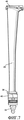
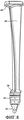
13. Турбина по п.9, в которой радиальная высота между осевой линией рабочего колеса и радиусом ступицы каждой лопасти лопатки около ее передней кромки составляет 100,383 см (39,521 дюймов), а безразмерная величина Z для Z=0,000 начинается с радиальной высоты 103,213 см (40,635 дюймов) от осевой линии рабочего колеса.13. The turbine according to claim 9, in which the radial height between the axial line of the impeller and the radius of the hub of each blade of the blade near its leading edge is 100.383 cm (39.521 inches), and the dimensionless value Z for Z = 0.000 begins with a radial height of 103.213 cm ( 40.635 inches) from the center line of the impeller. 14. Турбина по п.13, в которой высота лопасти лопатки от Z=0 до Z=1,0 составляет 56,416 см (22,211 дюйма).14. The turbine of claim 13, wherein the height of the blade of the blade from Z = 0 to Z = 1.0 is 56.416 cm (22.211 inches). 15. Турбина (12), содержащая рабочее колесо (29), имеющее множество лопаток (28), каждая из вышеупомянутых лопаток включает в себя лопасть (36), имеющую расчетный профиль без покрытия, по существу соответствующий значениям декартовых координат X, Y и Z, приведенным в Таблице 1, где величины Z являются безразмерными в диапазоне от 0 до 1, преобразуемые в расстояния Z в дюймах путем умножения значений Z на высоту лопасти в дюймах, и где Х и Y являются расстояниями в дюймах, которые при соединении плавными непрерывными дугами определяют сечения (48) профиля лопасти на каждом расстоянии Z, причем сечения профиля на расстояниях Z при соединении плавно друг с другом образуют завершенную форму лопасти, причем значения Х и Y являются масштабируемыми, являясь функцией от одной и той же константы или числа для обеспечения увеличения или уменьшения лопасти.15. A turbine (12) containing an impeller (29) having a plurality of blades (28), each of the aforementioned blades includes a blade (36) having a design profile without coating, essentially corresponding to the values of the Cartesian coordinates X, Y and Z shown in Table 1, where the Z values are dimensionless in the range from 0 to 1, converted to Z distances in inches by multiplying the Z values by the blade height in inches, and where X and Y are the distances in inches, which when connected by smooth continuous arcs determine the section (48) of the profile of the lop parts at each distance Z, and profile sections at distances Z, when connected smoothly with each other, form a complete blade shape, the values of X and Y being scalable, being a function of the same constant or number to ensure the increase or decrease of the blade. 16. Турбина по п.15, в которой рабочее колесо включает в себя четвертую ступень турбины.16. The turbine of claim 15, wherein the impeller includes a fourth stage of the turbine. 17. Турбина по п.15, в которой рабочее колесо имеет 88 лопаток и Х представляет собой расстояние, параллельное оси вращения турбины.17. The turbine of claim 15, wherein the impeller has 88 blades and X is a distance parallel to the axis of rotation of the turbine. 18. Турбина по п.15, в которой высота лопасти лопатки при значениях от Z=0 до Z=1,0 составляет 56,416 см (22,211 дюйма).18. The turbine according to claim 15, wherein the height of the blade of the blade with values from Z = 0 to Z = 1.0 is 56.416 cm (22.211 inches). 19. Турбина по п.15, в которой радиальная высота между осевой линией рабочего колеса и радиусом ступицы каждой лопасти лопатки около ее передней кромки составляет 100,383 см (39,521 дюймов), а безразмерная величина Z для Z=0,000 начинается с радиальной высоты 103,213 см (40,635 дюймов) от осевой линии рабочего колеса.19. The turbine according to claim 15, wherein the radial height between the axial line of the impeller and the radius of the hub of each blade of the blade near its leading edge is 100.383 cm (39.521 inches), and the dimensionless value Z for Z = 0.000 begins with a radial height of 103.213 cm ( 40.635 inches) from the center line of the impeller. 20. Турбина по п.19, в которой высота лопасти лопатки от Z=0 до Z=1,0 составляет 56,416 см (22,211 дюйма). 20. The turbine according to claim 19, in which the height of the blade blades from Z = 0 to Z = 1.0 is 56.416 cm (22.211 inches).
RU2004121998/06A 2003-07-18 2004-07-16 Turbine blade aerodynamic profile (versions) and turbine (versions) RU2350756C2 (en)

Applications Claiming Priority (2)

Application Number Priority Date Filing Date Title
US10/621,460 2003-07-18
US10/621,460 US6884038B2 (en) 2003-07-18 2003-07-18 Airfoil shape for a turbine bucket

Publications (2)

Publication Number Publication Date
RU2004121998A RU2004121998A (en) 2006-01-20
RU2350756C2 true RU2350756C2 (en) 2009-03-27

Family

ID=33477115

Family Applications (1)

Application Number Title Priority Date Filing Date
RU2004121998/06A RU2350756C2 (en) 2003-07-18 2004-07-16 Turbine blade aerodynamic profile (versions) and turbine (versions)

Country Status (6)

Country Link
US (1) US6884038B2 (en)
EP (1) EP1498577A3 (en)
JP (1) JP2005042716A (en)
KR (1) KR100880293B1 (en)
CN (1) CN100359135C (en)
RU (1) RU2350756C2 (en)

Cited By (2)

* Cited by examiner, † Cited by third party
Publication number Priority date Publication date Assignee Title
RU2518767C2 (en) * 2009-03-27 2014-06-10 Дженерал Электрик Компани Turbine blade and turbine wheel with said blades
RU2606736C2 (en) * 2011-11-28 2017-01-10 Дженерал Электрик Компани Turbine nozzle vane (versions) and turbine with nozzle vanes

Families Citing this family (47)

* Cited by examiner, † Cited by third party
Publication number Priority date Publication date Assignee Title
US7186090B2 (en) * 2004-08-05 2007-03-06 General Electric Company Air foil shape for a compressor blade
ITMI20041804A1 (en) * 2004-09-21 2004-12-21 Nuovo Pignone Spa SHOVEL OF A RUTOR OF A FIRST STAGE OF A GAS TURBINE
US20060216144A1 (en) 2005-03-28 2006-09-28 Sullivan Michael A First and second stage turbine airfoil shapes
FR2889308B1 (en) * 2005-07-28 2007-10-05 Snecma CONTROL OF TURBOMACHINE AUBES
CA2633337C (en) * 2005-12-29 2014-11-18 Rolls-Royce Power Engineering Plc Airfoil for a second stage nozzle guide vane
CA2633319C (en) * 2005-12-29 2013-02-19 Rolls-Royce Power Engineering Plc First stage turbine airfoil
US7618240B2 (en) * 2005-12-29 2009-11-17 Rolls-Royce Power Engineering Plc Airfoil for a first stage nozzle guide vane
US7722329B2 (en) 2005-12-29 2010-05-25 Rolls-Royce Power Engineering Plc Airfoil for a third stage nozzle guide vane
CA2634738C (en) * 2005-12-29 2013-03-26 Rolls-Royce Power Engineering Plc Second stage turbine airfoil
US7632072B2 (en) * 2005-12-29 2009-12-15 Rolls-Royce Power Engineering Plc Third stage turbine airfoil
US7329093B2 (en) * 2006-01-27 2008-02-12 General Electric Company Nozzle blade airfoil profile for a turbine
US7329092B2 (en) * 2006-01-27 2008-02-12 General Electric Company Stator blade airfoil profile for a compressor
US7306436B2 (en) * 2006-03-02 2007-12-11 Pratt & Whitney Canada Corp. HP turbine blade airfoil profile
US7396211B2 (en) * 2006-03-30 2008-07-08 General Electric Company Stator blade airfoil profile for a compressor
US7467926B2 (en) * 2006-06-09 2008-12-23 General Electric Company Stator blade airfoil profile for a compressor
US7581930B2 (en) * 2006-08-16 2009-09-01 United Technologies Corporation High lift transonic turbine blade
US7611326B2 (en) * 2006-09-06 2009-11-03 Pratt & Whitney Canada Corp. HP turbine vane airfoil profile
US7572105B2 (en) * 2006-10-25 2009-08-11 General Electric Company Airfoil shape for a compressor
US7494321B2 (en) * 2006-10-25 2009-02-24 General Electric Company Airfoil shape for a compressor
US7517197B2 (en) * 2006-10-25 2009-04-14 General Electric Company Airfoil shape for a compressor
US7510378B2 (en) * 2006-10-25 2009-03-31 General Electric Company Airfoil shape for a compressor
US7572104B2 (en) * 2006-10-25 2009-08-11 General Electric Company Airfoil shape for a compressor
US7494322B2 (en) * 2006-10-25 2009-02-24 General Electric Company Airfoil shape for a compressor
US7494323B2 (en) * 2006-10-25 2009-02-24 General Electric Company Airfoil shape for a compressor
US7566202B2 (en) * 2006-10-25 2009-07-28 General Electric Company Airfoil shape for a compressor
US7513748B2 (en) * 2006-10-25 2009-04-07 General Electric Company Airfoil shape for a compressor
US7497663B2 (en) * 2006-10-26 2009-03-03 General Electric Company Rotor blade profile optimization
US7568892B2 (en) * 2006-11-02 2009-08-04 General Electric Company Airfoil shape for a compressor
US7497665B2 (en) * 2006-11-02 2009-03-03 General Electric Company Airfoil shape for a compressor
US7559748B2 (en) * 2006-11-28 2009-07-14 Pratt & Whitney Canada Corp. LP turbine blade airfoil profile
US7731483B2 (en) * 2007-08-01 2010-06-08 General Electric Company Airfoil shape for a turbine bucket and turbine incorporating same
US8147188B2 (en) * 2007-09-28 2012-04-03 General Electric Company Air cooled bucket for a turbine
US8052395B2 (en) * 2007-09-28 2011-11-08 General Electric Company Air cooled bucket for a turbine
US8647069B2 (en) * 2010-07-26 2014-02-11 Snecma Optimized aerodynamic profile for a turbine blade, in particular for a rotary wheel of the fourth stage of a turbine
US8734113B2 (en) 2010-07-26 2014-05-27 Snecma Optimized aerodynamic profile for a turbine vane, in particular for a nozzle of the fourth stage of a turbine
US8757968B2 (en) * 2010-07-26 2014-06-24 Snecma Optimized aerodynamic profile for a turbine vane, in particular for a nozzle of the third stage of a turbine
US8602740B2 (en) 2010-09-08 2013-12-10 United Technologies Corporation Turbine vane airfoil
US8393870B2 (en) 2010-09-08 2013-03-12 United Technologies Corporation Turbine blade airfoil
US9011101B2 (en) * 2011-11-28 2015-04-21 General Electric Company Turbine bucket airfoil profile
US8740570B2 (en) * 2011-11-28 2014-06-03 General Electric Company Turbine bucket airfoil profile
CN104420887B (en) * 2013-08-30 2016-06-15 哈尔滨汽轮机厂有限责任公司 A kind of turbine of gas turbine
DE102014009256A1 (en) * 2014-06-20 2015-12-24 Audi Ag Routers and methods for receiving and distributing data
US10480323B2 (en) 2016-01-12 2019-11-19 United Technologies Corporation Gas turbine engine turbine blade airfoil profile
US10519783B2 (en) * 2016-12-22 2019-12-31 General Electric Company Method for modifying a shroud and blade
US10422227B2 (en) * 2017-05-02 2019-09-24 General Electric Company Airfoil shape for a turbine rotor blade
US10590772B1 (en) * 2018-08-21 2020-03-17 Chromalloy Gas Turbine Llc Second stage turbine blade
US11441427B1 (en) * 2021-04-30 2022-09-13 General Electric Company Compressor rotor blade airfoils

Family Cites Families (9)

* Cited by examiner, † Cited by third party
Publication number Priority date Publication date Assignee Title
US5980209A (en) * 1997-06-27 1999-11-09 General Electric Co. Turbine blade with enhanced cooling and profile optimization
US6461110B1 (en) * 2001-07-11 2002-10-08 General Electric Company First-stage high pressure turbine bucket airfoil
US6474948B1 (en) * 2001-06-22 2002-11-05 General Electric Company Third-stage turbine bucket airfoil
US6450770B1 (en) * 2001-06-28 2002-09-17 General Electric Company Second-stage turbine bucket airfoil
US6503059B1 (en) * 2001-07-06 2003-01-07 General Electric Company Fourth-stage turbine bucket airfoil
US6558122B1 (en) * 2001-11-14 2003-05-06 General Electric Company Second-stage turbine bucket airfoil
US6715990B1 (en) * 2002-09-19 2004-04-06 General Electric Company First stage turbine bucket airfoil
US6722852B1 (en) * 2002-11-22 2004-04-20 General Electric Company Third stage turbine bucket airfoil
US6736599B1 (en) * 2003-05-14 2004-05-18 General Electric Company First stage turbine nozzle airfoil

Cited By (2)

* Cited by examiner, † Cited by third party
Publication number Priority date Publication date Assignee Title
RU2518767C2 (en) * 2009-03-27 2014-06-10 Дженерал Электрик Компани Turbine blade and turbine wheel with said blades
RU2606736C2 (en) * 2011-11-28 2017-01-10 Дженерал Электрик Компани Turbine nozzle vane (versions) and turbine with nozzle vanes

Also Published As

Publication number Publication date
KR20050009957A (en) 2005-01-26
JP2005042716A (en) 2005-02-17
EP1498577A2 (en) 2005-01-19
EP1498577A3 (en) 2012-04-25
CN100359135C (en) 2008-01-02
RU2004121998A (en) 2006-01-20
KR100880293B1 (en) 2009-01-23
US6884038B2 (en) 2005-04-26
US20050013695A1 (en) 2005-01-20
CN1584296A (en) 2005-02-23

Similar Documents

Publication Publication Date Title
RU2350756C2 (en) Turbine blade aerodynamic profile (versions) and turbine (versions)
CN103511341B (en) Aerofoil profile product for compressor reducer
CN103510997B (en) Airfoil shape for use in compressor
RU2505711C2 (en) Radial flow compressor diffuser
US7497665B2 (en) Airfoil shape for a compressor
US7517188B2 (en) Airfoil shape for a compressor
US7572105B2 (en) Airfoil shape for a compressor
US7517196B2 (en) Airfoil shape for a compressor
US7520729B2 (en) Airfoil shape for a compressor
US7537434B2 (en) Airfoil shape for a compressor
US7517190B2 (en) Airfoil shape for a compressor
US7513749B2 (en) Airfoil shape for a compressor
US7537435B2 (en) Airfoil shape for a compressor
US7419353B2 (en) Blade of a turbomachine with block-wise defined profile skeleton line
EP1577562A3 (en) Axial flow fan
US20080101956A1 (en) Airfoil shape for a compressor
US20080107537A1 (en) Airfoil shape for a compressor
US20080101952A1 (en) Airfoil shape for a compressor
US20080101954A1 (en) Airfoil shape for a compressor
US20080101949A1 (en) Airfoil shape for a compressor
US20080101945A1 (en) Airfoil shape for a compressor
US20080101948A1 (en) Airfoil shape for a compressor
US20080101940A1 (en) Airfoil shape for a compressor
US20080101953A1 (en) Airfoil shape for a compressor
US20080107536A1 (en) Airfoil shape for a compressor

Legal Events

Date Code Title Description
QB4A Licence on use of patent

Free format text: LICENCE

Effective date: 20130315

QB4A Licence on use of patent

Free format text: LICENCE

Effective date: 20140829

MM4A The patent is invalid due to non-payment of fees

Effective date: 20150717