EP1231050A2 - Appareil a bras oscillant, pour la fabrication d'un renfort de pneumatique a partir d'un fil - Google Patents
Appareil a bras oscillant, pour la fabrication d'un renfort de pneumatique a partir d'un fil Download PDFInfo
- Publication number
- EP1231050A2 EP1231050A2 EP02001862A EP02001862A EP1231050A2 EP 1231050 A2 EP1231050 A2 EP 1231050A2 EP 02001862 A EP02001862 A EP 02001862A EP 02001862 A EP02001862 A EP 02001862A EP 1231050 A2 EP1231050 A2 EP 1231050A2
- Authority
- EP
- European Patent Office
- Prior art keywords
- arm
- rotation
- wire
- geometric axis
- guide member
- Prior art date
- Legal status (The legal status is an assumption and is not a legal conclusion. Google has not performed a legal analysis and makes no representation as to the accuracy of the status listed.)
- Granted
Links
Images







Classifications
-
- B—PERFORMING OPERATIONS; TRANSPORTING
- B29—WORKING OF PLASTICS; WORKING OF SUBSTANCES IN A PLASTIC STATE IN GENERAL
- B29D—PRODUCING PARTICULAR ARTICLES FROM PLASTICS OR FROM SUBSTANCES IN A PLASTIC STATE
- B29D30/00—Producing pneumatic or solid tyres or parts thereof
- B29D30/06—Pneumatic tyres or parts thereof (e.g. produced by casting, moulding, compression moulding, injection moulding, centrifugal casting)
- B29D30/08—Building tyres
- B29D30/10—Building tyres on round cores, i.e. the shape of the core is approximately identical with the shape of the completed tyre
- B29D30/16—Applying the layers; Guiding or stretching the layers during application
- B29D30/1635—Applying the layers; Guiding or stretching the layers during application by feeding a continuous band and moving it back and forth (zig-zag) to form an annular element
-
- B—PERFORMING OPERATIONS; TRANSPORTING
- B29—WORKING OF PLASTICS; WORKING OF SUBSTANCES IN A PLASTIC STATE IN GENERAL
- B29D—PRODUCING PARTICULAR ARTICLES FROM PLASTICS OR FROM SUBSTANCES IN A PLASTIC STATE
- B29D30/00—Producing pneumatic or solid tyres or parts thereof
- B29D30/06—Pneumatic tyres or parts thereof (e.g. produced by casting, moulding, compression moulding, injection moulding, centrifugal casting)
- B29D30/08—Building tyres
-
- B—PERFORMING OPERATIONS; TRANSPORTING
- B29—WORKING OF PLASTICS; WORKING OF SUBSTANCES IN A PLASTIC STATE IN GENERAL
- B29D—PRODUCING PARTICULAR ARTICLES FROM PLASTICS OR FROM SUBSTANCES IN A PLASTIC STATE
- B29D30/00—Producing pneumatic or solid tyres or parts thereof
- B29D30/06—Pneumatic tyres or parts thereof (e.g. produced by casting, moulding, compression moulding, injection moulding, centrifugal casting)
- B29D30/70—Annular breakers
-
- B—PERFORMING OPERATIONS; TRANSPORTING
- B29—WORKING OF PLASTICS; WORKING OF SUBSTANCES IN A PLASTIC STATE IN GENERAL
- B29D—PRODUCING PARTICULAR ARTICLES FROM PLASTICS OR FROM SUBSTANCES IN A PLASTIC STATE
- B29D30/00—Producing pneumatic or solid tyres or parts thereof
- B29D30/06—Pneumatic tyres or parts thereof (e.g. produced by casting, moulding, compression moulding, injection moulding, centrifugal casting)
- B29D30/08—Building tyres
- B29D30/10—Building tyres on round cores, i.e. the shape of the core is approximately identical with the shape of the completed tyre
- B29D30/16—Applying the layers; Guiding or stretching the layers during application
- B29D2030/1664—Details, accessories or auxiliary operations not provided for in the other subgroups of B29D30/00
- B29D2030/1678—Details, accessories or auxiliary operations not provided for in the other subgroups of B29D30/00 the layers being applied being substantially continuous, i.e. not being cut before the application step
Definitions
- the present invention relates to the manufacture of tires. More specifically, it relates when placing wires to reinforce the tire. More specifically, it offers means capable of manufacturing such a reinforcement on a similar or identical form the shape of the internal cavity of the tire, that is to say a substantially toroidal shape, supporting the blank of a tire during its manufacture.
- patent application EP 0 962 304 there is known an apparatus also provided for the realization carcass reinforcements on a rigid core whose external surface corresponds substantially in the shape of the internal cavity of the final tire.
- a single swing arm whose end, supporting a guide member comparable to the eyecup mentioned above necessarily describes arcs of a circle.
- FIG. 3 of said patent application EP 0 962 304 The problem which arises is that if one wishes to operate at rapid installation rates, the amplitude of the angles and characteristic radii of the described arc is not too large. It is also appropriate that the ends of the circular arc are not too far from the bead, i.e. from the area effective wire removal.
- the objective of the present invention is to provide equipment capable of operating according to the general process described in the aforementioned patent application EP 0 580 055, and capable of operate at high rates without prejudice to operating accuracy.
- the term "wire” must of course be understood in a very general sense, including a monofilament, a multifilament, an assembly like for example a cable or a twisted one, or a small number of cables or twisted together, and this whatever the nature of the material, and whether the "wire" is pre-coated with rubber or not.
- the term “hoop” is used to designate a section of wire going from a point singular to another in the reinforcing reinforcement. All of these arches arranged on everything the periphery of the tire forms the reinforcement itself.
- a hoop in the sense defined here may be part of a carcass, or a crown reinforcement, or any other type of reinforcement. These hoops can be individualized by cutting the wire during installation, or all connected between them in the final reinforcement, for example by loops.
- the invention deals with the continuous deposition of a reinforcing wire, in a configuration as close as possible to the configuration in the final product.
- the wire being delivered on demand by a suitable distributor comprising for example a spool of wire and the if necessary, a device for controlling the tension of the thread extracted from the spool, the manufacture of a reinforcement from a single wire cooperates with a shape (rigid core or a membrane) on which the tire is manufactured. It does not matter that the reinforcement is, for be complete, made in several successive rotations of the shape, with or without wire cutting between two rotations.
- the laying the wire described here also make it possible to carry out a reinforcement, for example a reinforcement carcass, in which the thread laying pitch is variable.
- no laying is meant the distance resulting from the sum of the difference between two adjacent wires and the wire diameter. It is well known that for a carcass reinforcement, the difference between wires varies according to the radius at which it is measured. he here is not a question of this variation, but of a variable step at a given radius. It is enough for that of, without changing the rate of work of the guide member, vary according to any law appropriate rotation speed of the form. A tire is thus obtained, the wires of which carcass reinforcement, for example for a radial carcass, are arranged in a pitch having a controlled variation for a given radial position.
- the apparatus causes the wire guide member to describe a movement substantially included in a plane - the plane of movement - perpendicular to the geometric axis of rotation of the first arm.
- the movement plane being distant from said first arm, and more precisely from its rotation shaft.
- the apparatus comprises means for controlling said swing arm, arranged to give the arm oscillating an oscillating movement around its geometric axis of rotation, the apparatus being arranged for the head of said arm to transport the guide member in a cyclic movement described in a movement plane, to bring the guide member in successive cycles to the vicinity of each of the ends desired for the wire in said trajectory.
- the apparatus comprises a second arm oscillating around a geometric axis of rotation, said axes of geometric rotation being substantially parallel, said second arm having a head transporting the guide member directly, or indirectly via one or more several other arms, the head of the first arm supporting the geometric axis of rotation of the second arm.
- the head of the second arm is radially distant from the axis geometric rotation of the second arm.
- the apparatus preferably comprises means for controlling the relative position of the second arm relative to said first arm so that the guide member is transported in a cyclic movement described in the movement plane, to bring the guide member into successive cycles in the vicinity of each of the ends desired for the wire in said path.
- an embodiment with a single sliding arm is also described below, used for manufacture a tire for PAX system, of which we know that the bead has a very specific shape, which makes it unnecessary for the head of the last arm, the one carrying the guide member, to be bent towards said form.
- this embodiment can also be used to manufacture conventional tires, therefore in particular with an arm curved towards said shape, and vice versa, this being said once and for all.
- the shape is a core 11 (rigid and removable) defining the geometry of the inner surface of the tire.
- the latter is coated with rubber 10, for example with a layer of sealing rubber based on butyl rubber, and with a layer of rubber ensuring the coating of the carcass wires.
- the rubber 10 covering the core 1 makes it possible to retain arches 40 of wire 4 on the core 1 as it is removed, by a bonding effect.
- the core 1 is rotated by any suitable device, not shown.
- the actual laying members essentially comprise a swing arm system 3 1a on the one hand, and pressing devices 2 G and 2 D on the other hand.
- the oscillating arm system 3 1a is mounted on a 3D oscillating shaft 1a which shows the geometric axis of rotation 31R 1a .
- the geometric axis of rotation 31R 1a cuts the core 1, in the operating position for laying wire 4 on the core.
- a box 30 1a comprises a mechanical control device, suitable for transforming the rotational movement of a motor 300 1a into a movement of oscillations printed on the 3D shaft 1a .
- the swing arm system 3 1a comprises a first swing arm 31 1a and a second swing arm 32 1a , arranged in cascade. This arrangement with two oscillating arms makes it easy to move the guide member from one bead to another, and therefore to obtain, in conjunction with the pressing devices 2 G and 2 D , an action of the one bead to another.
- the convention used is to designate similar members by the same main reference, for example “3” for the swing arm system, and to mark the specific membership of an embodiment or a variant by an alphanumeric indication placed by exposing, for example “ 1a ” for mode “1” (first mode) of embodiment (using a cascade of three oscillating arms), in its variant “a”.
- a reference without specific mark refers to a member always the same in the different variants or must be understood as designating all the variants of all the embodiments.
- the first arm 31 1a is mounted on the 3D oscillating shaft 1a .
- the first arm 31 1a has a head 31T 1a at the end opposite to the geometric axis of rotation 31R 1a .
- the second arm 32 1a articulated by a geometric axis of rotation 32R 1a of the second arm, is mounted on the head 31T 1a of the first arm 31 1a .
- the second arm 32 1a has a base 320 1a , oriented substantially perpendicular to the geometric axis of rotation 32R 1a .
- the second arm 32 1a has an intermediate portion 32I 1a developing substantially parallel to the geometric axis of rotation, in the direction of the plane of movement.
- the second arm 32 1a has a head 32T 1a , at the end of which there is an orifice 6 1a .
- a very advantageous feature of this first example concerns the guiding of the wire 4.
- the wire 4 is brought to an eyelet 301 1a , fixed in space, located substantially on the geometric axis of rotation 31R 1a of the first arm.
- the wire enters a hole arranged at the base of the second arm 32 1a and travels inside said second arm, said second arm being hollow.
- the guide member is constituted by an orifice 6 1a at the end of the second oscillating arm 32 1a .
- This orifice fulfills the function fulfilled by the eyepiece "33" in the abovementioned patent application EP 0 580 055. All the examples described relate to particularly advantageous embodiments comprising only two swinging arms. Consequently, the head of the second swinging arm directly transports the guide member.
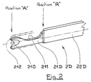
- the fork 21 has a head 210 in “V”, making it possible to take and center the wire 4.
- the plane formed by the "V” is arranged substantially perpendicular to the wire 4.
- the blade forming the fork 21 is oriented tangentially to a circle concentric with the core 1.
- the fork 21 has also an obviously 211 whose role will appear below.
- the fork 21 is intended to take the wire 4 against the core 1, then to keep it there. To this end, its advance towards the core 1 is triggered when the orifice 6 has brought the wire 4 to one end of the back and forth movement, i.e. when the device is substantially in the configuration of Figure 1.
- the fork 21 is stopped when it has anchored the wire in the rubber coating the core 1. Said fork 21 therefore makes it possible to press the wire 4 with sufficient force so that it adheres correctly in the desired location.
- the continued movement of the swingarm system 3 causes the formation of a loop around the point 212, which initiates the removal of a new hoop 40 on the core 1 (see figure 1).
- the passage of the orifice 6 beyond the fork 21 in the phase of return is allowed by obviously 211, although the fork 21 is pressed against the core 1 in this phase of manufacturing.
- the size of the loop is a function of the dimension from point 212.
- the hammer 22 intervenes after the fork 21 and after the so-called return phase of the orifice 6.
- the hammer 22 presses on the wire 4 at a slightly more radial position high. Preferably, it still retains the wire 4 while the fork 21 is retracted. hammer while the fork is retracting helps prevent the fork 21 from carrying with it the wire loop 4 which has formed around one of its points 212, and which even if it is glued on the rubber, could tend to remain attached to the fork.
- the anchoring of wire 4 in the bead is thus perfectly made reliable.
- the movement in the advanced position, and the return to the retracted position, both for the fork 21 and for the hammer 22 are controlled in synchronism with the swing arm system 3 1a , by any suitable device (movement return of the 3D shaft by an appropriate mechanical transmission, for example with belts or cable or by electrical synchronization between several motors).
- the swing arm system 3 1a causes the opening 6 1a to describe a movement passing over the core 1, and even bypassing it.
- the system with oscillating arms 3 causes the orifice 6 to pass through a movement in one plane, the "plane of movement".
- the oscillating arm system is printed with the appropriate movements.
- Said 3D oscillating shaft 1a does not perform continuous rotation, but oscillates within the limits of an arc whose precise value depends on the amplitude desired for the movement of the orifice 6 1a .
- the mechanical control device of the kind with connecting rod and crank or any other suitable arrangement, is easily designed according to a specification depending on the intended application and is driven by a motor 300 1a .
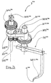
- the first arm supports a cascade of pinions (FIG. 3) having a first fixed pinion 311 1a centered on the geometric axis of rotation of the first arm, and an end pinion 313 1a centered on the geometric axis of rotation of the second arm and integral with the latter, and an intermediate pinion 312 1a meshing with the first pinion and the end pinion.
- the first pinion 311 1a fixed, is integral with the housing 30 1a .
- the pinions 312 1a and 313 1a are rotatably mounted on the first arm 31 1a .
- the first arm 31 1a is driven by a driving pinion 314 1a , itself driven alternately as explained above.
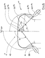
- the angle ⁇ (FIG. 4) represents the instantaneous position of the first arm 31 1a .
- the angle ⁇ varies over a sufficient amplitude for the deposited wire to reach the end of trajectory zones.
- the orifice 6 should go beyond the place where the pressure device 2 intervenes.
- the amplitude of the angular movement of the first arm 31 1a is quite large but the first arm is of short length and therefore of low inertia.
- a reduction of 12/18 is used.
- the amplitude of the angular movement of the second oscillating arm 32 1a remains compatible with high rates.
- FIG. 4 On the left side of Figure 4, there is shown a single arm apparatus 39, while on the right side of the same figure, there is shown an apparatus according to the first variant of the first embodiment.
- the core 1 1 is designed to make fairly narrow tires.
- the oscillating arm system requires much less free space around the core, because it moves less away from the core when it flies over the area of the future strip of rolling.
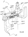
- this variant also includes a first arm 31 1b , a 3D oscillating shaft 1b , a geometric axis of rotation 31R 1b of the first arm 31 1b , a head 31T 1b at the end opposite to the geometric axis of rotation 31R 1b . It also includes a second arm 32 1b , having a geometric axis of rotation 32R 1b , a head 32T 1b , at the end of which there is the orifice 6 1b . There is also a cascade of three gables 311 1b , 312 1b and 313 1b . The first pinion 311 1b is fixed, secured to a housing not shown. The pinions 312 1b and 313 1b are rotatably mounted on the first arm 31 1b . The first arm 31 1b is driven by a driving pinion 314 1b , itself driven alternately as explained above.
- FIG. 6 On the left side of Figure 6, there is shown a single arm device 39, while on the right part of the same figure, there is shown a device according to the second variant of the first embodiment.
- the core 1 is designed to make wide tires.
- the single arm 39 directly comparable with regard to the depositing the wire on the blank of the future bead would move away a lot from the core when it flies over the future tread area.
- the system of the invention also has a significant gain inertia of the oscillating parts of the depositing system. The length, therefore the inertia moving parts is lower for the solution according to the invention.
- the orifice 6 describes a movement whose course is symmetrical with respect to this median plane, and reaches the vicinity of each of the bead zones defined on the core 1, in a movement perfectly symmetrical, this is not limiting. It is not excluded that the ends of the movement of the orifice are not at points symmetrical with respect to the median plane, for example to make a tire whose trajectory of the hoops is not symmetrical. This would be the case for manufacture a tire with the seat diameters (usual term to designate the seat of mounting) of each of the beads are different.
- FIG. 7 there is shown only a swing arm system 3 2a , without showing the shape on which the wire is deposited or the housing which supports it.
- a first arm 31 2a mounted on a 3D oscillating shaft 2a having a geometric axis of rotation 31R 2a .
- the first arm 31 2a has a head 31T 2a at the end opposite to the geometric axis of rotation 31R 2a .
- a second arm 32 2a is articulated by a geometric axis of rotation 32R 2a of the second arm on the head 31T 2a of the first arm 31 2a .
- the device comprises a fixed cam 33 2a hollowed out in a disc 330 2a centered on the geometric axis of rotation of the first arm.
- a cam follower 34 2a is engaged with said cam, the first arm comprising a shoe 35 2a whose movement is controlled by the cam follower.
- the second arm comprises a lever 312 2a substantially perpendicular to its geometric axis of rotation, the end of said lever being connected by a link 36 2a to the pad. This makes it possible to control the relative position of the second arm 32 2a relative to the first arm 31 2a .
- the second arm comprises a base 320 2a developing substantially parallel to the geometric axis of rotation, and comprises a head 32T 2a curved towards the geometric axis of rotation of the first arm 31 2a . At the end of the head 32T 2a , there is an orifice 6 2a .
- the second arm 32 2a is designed to move the orifice 6 2a to the plane of movement.
- FIG. 9 On the left side of Figure 9, there is shown a single arm apparatus 39, while on the right side of the same figure, there is shown an apparatus according to the second embodiment.
- the core 1 is designed to make fairly narrow tires.
- the angle ⁇ 'necessary for the device on the left to reach the bead without the intermediate part touching the shape, from a median position on the plane CP is greater than the angle ⁇ of the device right, according to the invention.
- the length of the first arm 31 2a is shorter than that of the arm 39.
- the length of the final spout formed by the head 32T 2a is much shorter than that of the spout 39T.
- the guard “d” existing between the form and the fitting device is directly comparable. We therefore see all the advantages of the invention.
- the relative movement between the second arm and the first arm can be adjusted fairly freely since it depends essentially on the profile of the cam.
- One is thus freed from the constraint of proportionality to the relative rotary movement between the first and the second arm, specific to the control by pinions of the first embodiment, or the second variant of the second mode. It is possible to impose a relative position of the second arm with respect to the first arm so as in particular to rapidly release the orifice 6 with respect to the core 1. This thus ensures an appropriate guard “d” between the head 32T 2a and the core 1, by getting close enough to the surface of the core 1 in the bead area.
- FIG. 10 illustrates an alternative embodiment of the second mode, in which a belt arrangement 36 2b provides a function comparable to the cam of the previous example.
- a 3D oscillating shaft 2b supporting a first arm 31 2b .
- the first arm 31 2b has a head 31T 2b .
- a second arm 32 2b is rotatably mounted on the head 31T 2b .
- the toothed belt 36 2b is mounted on a first pulley 360 2b centered on the geometric axis of rotation 31R 2b of the first arm.
- the first pulley 360 2b is not mobile in rotation.
- the toothed belt 36 2b is also mounted on a second pulley 361 2b centered on the geometric axis of rotation 32R 2b of the second arm 32 2b .
- the second pulley 361 2b is integral with said second arm.
- the belt 36 2b is also wound around a tension roller 362 2b and a deflection roller 363 2b , both fixed to the first arm 31 2b .
- the first arm 31 2b is mounted on a passage 3D1 2b arranged on the 3D tree 2b , and is immobilized by means of a flange 3D2 2b . There is thus a slide allowing the relative position of the first arm 31 2b to be modified on the 3D shaft 2b , in order to be able to adjust the distance between the geometric axes of rotation 31R 2b and 32R 2b .
- the tensioning roller 362 2b is mounted on the first arm 31 2b by means of a lug 365 2b comprising lights 364 2b .
- FIGS. 11 and 12 show an embodiment suitable for the manufacture of tires for the PAX system.
- the core 1 3 has a characteristic shape in the area of the beads.
- FIG. 11 there is shown only a swing arm system 3 3a , without showing the shape on which the wire is deposited or the housing which supports it.
- an arm 31 3a mounted on a 3D oscillating shaft 3a having a geometric axis of rotation 31R 3a .
- the arm 31 3a has a central portion 31C 3a intersecting the geometric axis of rotation 31R 3a and substantially perpendicular thereto.
- the device comprises a fixed cam 33 3a hollowed out in a disc 330 3a centered on the geometric axis of rotation of the arm.
- a cam follower 34 3a is engaged with said cam.
- the cam follower 34 3a is integral with the central portion 31C 3a , said central portion 31C 3a sliding radially relative to the 3D oscillating shaft 3a , and therefore relative to the geometric axis of rotation 31R 3a .
- the translational movement M2 of the arm 31 3a is controlled by the cam follower 34 3a .
- the 3D oscillating shaft 3a is integral with a driving pinion 314 3a , itself driven alternately as explained above (see explanations for the driving pinion 314 1b in Figure 5) to impart the movement M1.
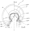
- the angle ⁇ (FIG. 12) represents the instantaneous position of the arm 31 3a .
- the angle ⁇ varies over a sufficient amplitude for the deposited wire to reach the end of trajectory zones.
- the orifice 6 should go beyond the place where the pressure device 2 intervenes.
- the central portion 31C 3a joins an end portion 31T 3a substantially parallel to said geometric axis of rotation 31R 3a and supporting the guide member 6 3a .
- the arm forms a square 31I 3a between the central portion 31C 3a and the end portion 31T 3a .
- At the end of the end portion 31T 3a there is an orifice 6 3a .
- the layout of the cam 33 3a is symmetrical relative to the plane CP.
- a person skilled in the art will adapt the layout of the cam to the case of an asymmetrical tire.
- the movement of the first arm can be adjusted to needs fairly freely since it essentially depends on the profile of the cam. We can get close enough to the surface of the core 1 in the bead area, without moving away from the surface of the nucleus around the plane CP.
- the previous examples illustrate devices in which the geometric axis of rotation of said at least one arm cuts the shape in the working position, the arm (s) being formed and arranged so that the guide member 6 goes around the shape, without moving too far away, the movement relative between guide member and shape determining said desired path for said wire at the surface of said shape.
- the preceding examples illustrate apparatuses laying sections of wires from a bead to the other bead.
- the carcass of a radial tire may not be continuous from one bead to another, but may be interrupted somewhere under the tread.
- the carcass reinforcement is then deposited between the bead and a shoulder.
- An apparatus according to the invention could just as easily be used for a bead action to any point under the tread, including to the opposite shoulder, with a certain degree of overlap of the half-carcasses, one on the other.
- orifice 6 in all variants, is animated by a cyclic movement in a plane, called above "orifice movement plane".
- the core 1 is rotated around of its axis while the orifice 6 performs its back and forth in the orifice movement plane.
- the movement of the core 1 is in synchronism with the back-and-forth movement of the orifice.
- the real trajectory of the hoops 40 of the wire 4 is therefore both a function of the fixed position relative (which can be tilted) between the plane of orifice movement and the core, and is a function of relative movement between the core 1 and the back and forth of the orifice 6.
- the trajectory of the arch 40 is substantially radial because it describes the production of a carcass for a radial tire, without this of course being limiting.
- the plane of movement could also form any angle, for example of the order of 20 °, relative to a plane perpendicular to the axis of rotation of the core 1, according to the usual conventions for measuring angles in the field of tires. .
- the pressure devices 2 G and 2 D act in the same removal plan.
- All the laying members namely the swing arm system 3 and the pressing devices 2, including the motor and the drive mechanism, forms a sub-assembly which can easily presented to the nucleus in an appropriate manner, and can be retracted for example present to the core other devices used for the manufacture of a tire or for evacuation of the core to other tire manufacturing stations.
- the invention makes it possible to manufacture a tire by a process in which a tire is manufactured. reinforcement from a wire, delivered continuously and on demand by an appropriate distributor, using a substantially toroidal shape on which said progressively is constructed reinforcement by depositing arches of said wire along a desired path for said wire at the surface of said shape, using any of the devices described, for applying sections of wire from one bead of the tire to the other bead.
- the process makes it possible to manufacture said reinforcement by depositing the hoops side by side of said wire on the surface of said form.
Landscapes
- Engineering & Computer Science (AREA)
- Mechanical Engineering (AREA)
- Tyre Moulding (AREA)
- Yarns And Mechanical Finishing Of Yarns Or Ropes (AREA)
- Heating, Cooling, Or Curing Plastics Or The Like In General (AREA)
Abstract
Description
ledit appareil comprenant :
- un organe de guidage dans lequel le fil peut coulisser librement,
- au moins un bras oscillant autour d'un axe géométrique de rotation ledit bras oscillant comportant une tête éloignée de son axe géométrique de rotation,
- des moyens de commande pour conférer audit bras oscillant un mouvement d'oscillation autour de son axe géométrique de rotation, l'appareil étant agencé pour que la tête dudit bras transporte l'organe de guidage directement, ou indirectement par l'intermédiaire d'un ou plusieurs autres bras oscillants,
- la tête du deuxième bras est recourbée vers ladite forme, et supporte directement l'organe de guidage, de façon à rapprocher l'organe de guidage de ladite forme au moins dans la configuration prise par l'appareil lorsque l'organe de guidage est proche de l'extrémité de ladite trajectoire ;
- ledit premier bras est sensiblement orienté perpendiculairement à son axe géométrique de rotation, le deuxième bras ayant au moins une partie intermédiaire orientée sensiblement parallèlement à l'axe géométrique de rotation du premier bras.
- le fil étant retenu contre la forme pendant un temps suffisant, déplacer l'orifice (organe de guidage) dans un plan de mouvement d'orifice jusqu'à une première extrémité,
- appliquer le fil sur la forme à cette première extrémité et l'y maintenir au moins un temps suffisant, au moyen d'un dispositif presseur,
- répéter la première étape en sens inverse jusqu'à une deuxième extrémité,
- appliquer le fil sur la forme à cette deuxième extrémité et l'y maintenir, au moyen d'un autre dispositif presseur,
Claims (20)
- Appareil de fabrication d'un renforcement pour pneumatique, ledit appareil étant destiné à fabriquer un renforcement constitué à partir d'un fil (4) délivré sensiblement en continu et à la demande par un distributeur approprié, ledit appareil étant destiné à être utilisé en coopération avec une forme (1) sensiblement toroïdale sur laquelle on construit progressivement ledit renforcement en déposant des arceaux dudit fil selon une trajectoire souhaitée pour ledit fil à la surface de ladite forme,
ledit appareil comprenant :ledit appareil étant destiné à être utilisé en coopération avec des presseurs (2G et 2D) proches de chaque extrémité de ladite trajectoire, pour appliquer le fil sur la forme auxdites extrémités,un organe de guidage (6) dans lequel le fil peut coulisser librement,au moins un bras (31) oscillant autour d'un axe géométrique de rotation, ledit bras oscillant comportant une tête (31T) éloignée de son axe géométrique de rotation (31R),des moyens de commande pour conférer audit bras oscillant un mouvement d'oscillation autour de son axe géométrique de rotation, l'appareil étant agencé pour que la tête dudit bras oscillant transporte l'organe de guidage (6) directement, ou indirectement par l'intermédiaire d'un ou plusieurs autres bras,
caractérisé en ce que
la distance radiale entre la tête (31T) et l'axe géométrique de rotation (31R) du bras est variable. - Appareil selon la revendication 1, comportant un deuxième bras (32) oscillant autour d'un axe géométrique de rotation (32R), lesdits axes géométriques de rotation étant sensiblement parallèles, ledit deuxième bras comportant une tête (32T) transportant l'organe de guidage directement, ou indirectement par l'intermédiaire d'un ou plusieurs autres bras, la tête (31T) du premier bras (31) supportant l'axe géométrique de rotation (32R) du deuxième bras (32)
- Appareil selon la revendication 2 dans lequel la tête (32T) du deuxième bras (32) est radialement éloignée de l'axe géométrique de rotation du deuxième bras (32R).
- Appareil selon la revendication 2 ou 3, comportant des moyens de commande de la position relative du deuxième bras par rapport audit premier bras de sorte que l'organe de guidage est transporté selon un mouvement cyclique pour amener l'organe de guidage en cycles successifs au voisinage de chacune des extrémités souhaitées pour le fil dans ladite trajectoire.
- Appareil selon l'une des revendications 2 à 4, dans lequel la tête (32T) du deuxième bras est recourbée vers ladite forme, et supporte directement l'organe de guidage (6), de façon à rapprocher l'organe de guidage de ladite forme au moins dans la configuration prise par l'appareil lorsque l'organe de guidage est proche de l'extrémité de ladite trajectoire.
- Appareil selon l'une des revendications 2 à 4, dans lequel ledit premier bras (31) est sensiblement orienté perpendiculairement à son axe géométrique de rotation, le deuxième bras (32) ayant au moins une partie intermédiaire (32I) orientée sensiblement parallèlement à l'axe géométrique de rotation du premier bras.
- Appareil selon l'une des revendications 2 à 6, dans lequel la base (320) du deuxième bras, incluant l'axe géométrique de rotation, est orientée sensiblement perpendiculairement à l'axe géométrique de rotation.
- Appareil selon la revendication 7, dans lequel le premier bras supporte une cascade de pignons ayant un premier pignon fixe (3111) centré sur l'axe géométrique de rotation du premier bras, et un pignon d'extrémité (3131) centré sur l'axe géométrique de rotation du deuxième bras et solidaire de celui-ci, et un pignon intermédiaire (3121) engrenant avec le premier pignon et le pignon d'extrémité.
- Appareil selon la revendication 8, dans lequel le nombre de dents Nf du pignon fixe (3111a) est inférieur au nombre de dents Ne du pignon d'extrémité(3131a), avec Nf= a Ne, le premier bras décrivant des oscillations d'amplitude α, α étant positif dans le sens trigonométrique inverse, le deuxième bras décrivant des oscillations d'amplitude β = 180°-aα autour de ladite forme, β étant positif dans le sens trigonométrique.
- Appareil selon la revendication 8, dans lequel le nombre de dents Nf du pignon fixe (3111b) est supérieur au nombre de dents Ne du pignon d'extrémité(3131b), avec Nf= a Ne, le premier bras décrivant des oscillations d'amplitude α dans l'espace du côté de son axe géométrique de rotation opposé à la forme, le deuxième bras décrivant des oscillations d'amplitude β = aα autour de ladite forme, α étant positif dans le sens trigonométrique inverse, β étant positif dans le sens trigonométrique.
- Appareil selon la revendication 7, dans lequel le premier bras (312b) supporte une courroie crantée (362b) montée sur une première poulie (3602b) centrée sur l'axe géométrique de rotation du premier bras, non mobile en rotation, et sur une deuxième poulie (3612b) centrée sur l'axe géométrique de rotation du deuxième bras (322b) et solidaire dudit deuxième bras.
- Appareil selon l'une des revendications 2 à 7, comportant une came fixe (332a) centrée sur l'axe géométrique de rotation du premier bras, dans lequel le premier bras supporte un suiveur de came (342a) en prise avec ladite came, le premier bras comportant un patin (352a) dont le mouvement est commandé par le suiveur de came, le deuxième bras comportant un levier (3122a) sensiblement perpendiculaire à son axe géométrique de rotation, l'extrémité dudit levier étant reliée par une biellette (362a) au patin.
- Appareil selon l'une des revendications 2 à 12, dans lequel la tête du deuxième bras oscillant transporte directement l'organe de guidage.
- Appareil selon la revendication 1 dans lequel ledit au moins un bras (313a) comporte une portion centrale (31C3a) coupant l'axe géométrique de rotation (31R3a) et sensiblement perpendiculaire à celui-ci, et rejoignant une portion d'extrémité (31T3a) sensiblement parallèle audit axe géométrique de rotation (31R3a) et supportant l'organe de guidage (63a), ladite portion centrale (31C3a) coulissant radialement par rapport à l'axe géométrique de rotation (31R3a).
- Appareil selon la revendication 14, comportant une came fixe (333a) et un suiveur de came (343a) en prise avec ladite came et solidaire de la portion centrale (31C3a), le mouvement de translation du bras (313a) étant contrôlé par le suiveur de came (343a).
- Appareil selon l'une des revendications 1 à 15, dans lequel l'axe géométrique de rotation dudit au moins un bras coupe la forme en position de travail, le ou les bras étant formé(s) et agencé(s) de façon à ce que l'organe de guidage (6) contourne la forme, le mouvement relatif entre organe de guidage et forme déterminant ladite trajectoire souhaitée pour ledit fil à la surface de ladite forme.
- Appareil selon l'une des revendications 1 à 16, dans lequel l'organe de guidage est constitué par un orifice à l'extrémité du deuxième bras oscillant, ledit deuxième bras étant creux et parcouru par ledit fil.
- Appareil selon l'une des revendications 1 à 17, dans lequel lesdits moyens de commande du bras oscillant transporte l'organe de guidage (6) selon un mouvement cyclique décrit dans un plan de mouvement, pour amener l'organe de guidage en cycles successifs au voisinage de chacune des extrémités souhaitées pour le fil dans ladite trajectoire.
- Procédé de fabrication d'un pneumatique, dans lequel on fabrique un renforcement à partir d'un fil délivré sensiblement en continu et à la demande par un distributeur approprié, utilisant une forme sensiblement toroïdale sur laquelle on construit progressivement ledit renforcement en déposant des arceaux dudit fil selon une trajectoire souhaitée pour ledit fil à la surface de ladite forme, au moyen d'un appareil selon l'une des revendications 1 à 11 et selon un mouvement cyclique décrit dans un plan de mouvement, pour amener l'organe de guidage en cycles successifs au voisinage de chacune des extrémités souhaitées pour le fil dans ladite trajectoire, ledit appareil comportant en outre des presseurs (2G et 2D) proches de chaque extrémité de ladite trajectoire, pour appliquer le fil sur la forme auxdites extrémités, en agissant en synchronisme avec ledit mouvement cyclique de l'organe de guidage, appliquant des tronçons de fil d'un des bourrelets du pneumatique à l'autre bourrelet.
- Procédé de fabrication d'un pneumatique selon la revendication 19, dans lequel on fabrique ledit renforcement en déposant côte à côte les arceaux dudit fil à la surface de ladite forme.
Priority Applications (1)
| Application Number | Priority Date | Filing Date | Title |
|---|---|---|---|
| EP05002379A EP1537985B1 (fr) | 2001-02-07 | 2002-01-28 | Appareil à bras oscillant, pour la fabrication d'un renfort de pneumatique à partir d'un seul fil |
Applications Claiming Priority (2)
| Application Number | Priority Date | Filing Date | Title |
|---|---|---|---|
| FR0101748 | 2001-02-07 | ||
| FR0101748 | 2001-02-07 |
Related Child Applications (2)
| Application Number | Title | Priority Date | Filing Date |
|---|---|---|---|
| EP05002379A Division EP1537985B1 (fr) | 2001-02-07 | 2002-01-28 | Appareil à bras oscillant, pour la fabrication d'un renfort de pneumatique à partir d'un seul fil |
| EP05002379.5 Division-Into | 2005-02-04 |
Publications (3)
| Publication Number | Publication Date |
|---|---|
| EP1231050A2 true EP1231050A2 (fr) | 2002-08-14 |
| EP1231050A3 EP1231050A3 (fr) | 2003-05-02 |
| EP1231050B1 EP1231050B1 (fr) | 2005-11-09 |
Family
ID=8859807
Family Applications (2)
| Application Number | Title | Priority Date | Filing Date |
|---|---|---|---|
| EP05002379A Expired - Lifetime EP1537985B1 (fr) | 2001-02-07 | 2002-01-28 | Appareil à bras oscillant, pour la fabrication d'un renfort de pneumatique à partir d'un seul fil |
| EP02001862A Expired - Lifetime EP1231050B1 (fr) | 2001-02-07 | 2002-01-28 | Appareil à bras oscillant, pour la fabrication d'un renfort de pneumatique à partir d'un fil |
Family Applications Before (1)
| Application Number | Title | Priority Date | Filing Date |
|---|---|---|---|
| EP05002379A Expired - Lifetime EP1537985B1 (fr) | 2001-02-07 | 2002-01-28 | Appareil à bras oscillant, pour la fabrication d'un renfort de pneumatique à partir d'un seul fil |
Country Status (10)
| Country | Link |
|---|---|
| US (2) | US6887327B2 (fr) |
| EP (2) | EP1537985B1 (fr) |
| JP (1) | JP2002273799A (fr) |
| KR (1) | KR20020065850A (fr) |
| CN (1) | CN100400275C (fr) |
| AT (2) | ATE368563T1 (fr) |
| BR (1) | BR0200323A (fr) |
| DE (2) | DE60207119T2 (fr) |
| ES (1) | ES2252328T3 (fr) |
| RU (1) | RU2285614C2 (fr) |
Cited By (1)
| Publication number | Priority date | Publication date | Assignee | Title |
|---|---|---|---|---|
| FR3163301A1 (fr) * | 2024-06-18 | 2025-12-19 | Compagnie Generale Des Etablissements Michelin | Outillage de pose de haubans dans des passages prévus sur un outillage de fabrication d’un objet toroïdal et bandage pneumatique renforcé par des haubans posé par ledit outillage de pose |
Families Citing this family (18)
| Publication number | Priority date | Publication date | Assignee | Title |
|---|---|---|---|---|
| FR2827806A1 (fr) | 2001-07-26 | 2003-01-31 | Michelin Soc Tech | Appareil de fabrication d'un renforcement pour pneumatique |
| ATE340070T1 (de) * | 2002-12-04 | 2006-10-15 | Michelin Soc Tech | Vorrichtung zur herstellung eines verstärkungselements für grossformatige luftreifen |
| FR2848141A1 (fr) * | 2002-12-04 | 2004-06-11 | Michelin Soc Tech | Appareil de fabrication d'un renforcement pour pneumatique, a bras de pose multiples comportant un mouvement guide par un suiveur de came coulissant dans une lumiere |
| US20040154727A1 (en) * | 2003-02-11 | 2004-08-12 | Weissert James Thomas | Method and apparatus for manufacturing carcass plies for a tire |
| FR2877873B1 (fr) * | 2004-11-12 | 2007-02-09 | Michelin Soc Tech | Appareil de fabrication d'un renforcement pour pneumatique |
| US7568512B2 (en) * | 2005-06-17 | 2009-08-04 | Michelin Recherche Et Technique S.A. | Device for laying reinforcement cord |
| US20070125478A1 (en) * | 2005-12-01 | 2007-06-07 | Weissert James T | Tire cord application station and method |
| US20070125471A1 (en) * | 2005-12-01 | 2007-06-07 | Weissert James T | Split cord geodesic configurations for a tire |
| US7686053B2 (en) * | 2005-12-01 | 2010-03-30 | The Goodyear Tire & Rubber Company | Cord tensioning and feed mechanism for a tire cord applicator head |
| US7740039B2 (en) * | 2005-12-01 | 2010-06-22 | The Goodyear Tire & Rubber Company | Cord cutting mechanism and method for a tire cord applicator head |
| US7753098B2 (en) * | 2005-12-01 | 2010-07-13 | The Goodyear Tire & Rubber Company | Spring loaded tooling head and method for tire cord application |
| US20070125480A1 (en) * | 2005-12-01 | 2007-06-07 | Henthorne David A | Synchronous drive and method for tire cord application |
| US20070125482A1 (en) * | 2005-12-01 | 2007-06-07 | Weissert James T | Bi-directional tooling head and method for tire cord application |
| US8578994B2 (en) | 2006-12-19 | 2013-11-12 | The Goodyear Tire & Rubber Company | Applicator head for tire cord construction |
| KR101331920B1 (ko) * | 2007-09-10 | 2013-11-21 | 피렐리 타이어 소시에떼 퍼 아찌오니 | 차량 타이어용 보강구조를 만드는 공정 및 장치 |
| US10307980B2 (en) | 2013-02-20 | 2019-06-04 | The Goodyear Tire & Rubber Company | Tire building applicator members and systems |
| FR3105081B1 (fr) * | 2019-12-20 | 2021-11-19 | Michelin & Cie | Machine de fabrication automatique de bandages pneumatiques à sommet dit « polarisé » |
| CN115467179B (zh) * | 2022-10-08 | 2023-12-15 | 江苏亚盛金属制品有限公司 | 一种不锈钢丝多股绞合装置 |
Citations (2)
| Publication number | Priority date | Publication date | Assignee | Title |
|---|---|---|---|---|
| EP0580055A1 (fr) | 1992-07-21 | 1994-01-26 | Sedepro | Procédé et machine pour la mise en place sur noyau d'un seul fil de renfort dans la fabrication d'une carcasse de pneumatique |
| EP0962304A2 (fr) | 1998-06-01 | 1999-12-08 | Bridgestone Corporation | Procédé et dispositif pour la fabrication de pneumatiques |
Family Cites Families (10)
| Publication number | Priority date | Publication date | Assignee | Title |
|---|---|---|---|---|
| GB179312A (en) * | 1921-02-03 | 1922-05-03 | Dunlop Rubber Co | Improvements in or relating to machines for making pneumatic tyre covers or casings |
| WO1981001119A1 (fr) * | 1979-10-29 | 1981-04-30 | Caterpillar Tractor Co | Appareil et procede de fixation et baguage d'un materiau |
| SU1420797A1 (ru) * | 1983-11-30 | 1994-07-15 | Всесоюзный Научно-Исследовательский И Конструкторский Институт По Оборудованию Для Шинной Промышленности | Устройство для наложения усиливающего слоя каркаса покрышек |
| FR2597784B1 (fr) * | 1986-04-25 | 1990-10-26 | Michelin & Cie | Procede et appareil de fabrication de renforcements pour pneumatiques |
| FR2635043B1 (fr) * | 1988-08-05 | 1990-09-28 | Michelin & Cie | Appareil de fabrication d'un renforcement pour pneumatiques, ledit renforcement etant constitue a partir d'un seul fil |
| US5159249A (en) * | 1989-05-16 | 1992-10-27 | Dalila Megherbi | Method and apparatus for controlling robot motion at and near singularities and for robot mechanical design |
| FR2694519A1 (fr) * | 1992-08-07 | 1994-02-11 | Sedepro | Procédé de fabrication d'un pneumatique et machine de fabrication d'un renfort de sommet pour pneumatique. |
| FR2804367B1 (fr) | 2000-02-01 | 2002-09-20 | Sedepro | Appareil a bras oscillant, pour la fabrication d'un renfort de pneumatique a partir d'un seul fil |
| JP4315548B2 (ja) * | 1999-11-19 | 2009-08-19 | 株式会社ブリヂストン | タイヤカーカスの形成装置および形成方法 |
| FR2804368A1 (fr) * | 2000-02-01 | 2001-08-03 | Sedepro | Appareil pour la fabrication de renforts pour pneumatique |
-
2002
- 2002-01-28 ES ES02001862T patent/ES2252328T3/es not_active Expired - Lifetime
- 2002-01-28 AT AT05002379T patent/ATE368563T1/de not_active IP Right Cessation
- 2002-01-28 EP EP05002379A patent/EP1537985B1/fr not_active Expired - Lifetime
- 2002-01-28 AT AT02001862T patent/ATE309084T1/de not_active IP Right Cessation
- 2002-01-28 DE DE60207119T patent/DE60207119T2/de not_active Expired - Fee Related
- 2002-01-28 DE DE60221580T patent/DE60221580T2/de not_active Expired - Fee Related
- 2002-01-28 EP EP02001862A patent/EP1231050B1/fr not_active Expired - Lifetime
- 2002-02-05 US US10/067,395 patent/US6887327B2/en not_active Expired - Fee Related
- 2002-02-05 BR BR0200323-6A patent/BR0200323A/pt active Search and Examination
- 2002-02-06 KR KR1020020006658A patent/KR20020065850A/ko not_active Withdrawn
- 2002-02-06 RU RU2002103464/12A patent/RU2285614C2/ru active
- 2002-02-06 JP JP2002030126A patent/JP2002273799A/ja active Pending
- 2002-02-07 CN CNB021035946A patent/CN100400275C/zh not_active Expired - Fee Related
-
2005
- 2005-04-29 US US11/118,138 patent/US7285176B2/en not_active Expired - Fee Related
Patent Citations (2)
| Publication number | Priority date | Publication date | Assignee | Title |
|---|---|---|---|---|
| EP0580055A1 (fr) | 1992-07-21 | 1994-01-26 | Sedepro | Procédé et machine pour la mise en place sur noyau d'un seul fil de renfort dans la fabrication d'une carcasse de pneumatique |
| EP0962304A2 (fr) | 1998-06-01 | 1999-12-08 | Bridgestone Corporation | Procédé et dispositif pour la fabrication de pneumatiques |
Cited By (2)
| Publication number | Priority date | Publication date | Assignee | Title |
|---|---|---|---|---|
| FR3163301A1 (fr) * | 2024-06-18 | 2025-12-19 | Compagnie Generale Des Etablissements Michelin | Outillage de pose de haubans dans des passages prévus sur un outillage de fabrication d’un objet toroïdal et bandage pneumatique renforcé par des haubans posé par ledit outillage de pose |
| WO2025262380A1 (fr) * | 2024-06-18 | 2025-12-26 | Compagnie Generale Des Etablissements Michelin | Outillage de pose de haubans dans des passages prévus sur un outillage de fabrication d'un objet toroïdal et bandage pneumatique renforcé par des haubans posés par ledit outillage de pose |
Also Published As
| Publication number | Publication date |
|---|---|
| ES2252328T3 (es) | 2006-05-16 |
| US20050189062A1 (en) | 2005-09-01 |
| BR0200323A (pt) | 2002-10-29 |
| EP1537985B1 (fr) | 2007-08-01 |
| CN1369387A (zh) | 2002-09-18 |
| ATE309084T1 (de) | 2005-11-15 |
| US7285176B2 (en) | 2007-10-23 |
| US20020117265A1 (en) | 2002-08-29 |
| JP2002273799A (ja) | 2002-09-25 |
| DE60207119T2 (de) | 2006-07-27 |
| ATE368563T1 (de) | 2007-08-15 |
| DE60221580T2 (de) | 2008-04-17 |
| DE60207119D1 (de) | 2005-12-15 |
| EP1231050B1 (fr) | 2005-11-09 |
| EP1231050A3 (fr) | 2003-05-02 |
| DE60221580D1 (de) | 2007-09-13 |
| EP1537985A3 (fr) | 2005-06-15 |
| US6887327B2 (en) | 2005-05-03 |
| RU2285614C2 (ru) | 2006-10-20 |
| KR20020065850A (ko) | 2002-08-14 |
| CN100400275C (zh) | 2008-07-09 |
| EP1537985A2 (fr) | 2005-06-08 |
Similar Documents
| Publication | Publication Date | Title |
|---|---|---|
| EP1231050B1 (fr) | Appareil à bras oscillant, pour la fabrication d'un renfort de pneumatique à partir d'un fil | |
| EP1122057B1 (fr) | Appareil à bras occillant, pour la fabrication d'un renfort de pneumatique à partir d'un seul fil | |
| CA2101001C (fr) | Procede et machine de fabrication d'un pneumatique dont le renfort de carcasse est constitue sur noyau, a partir d'un seul fil | |
| EP1231049B1 (fr) | Appareil a bras oscillant unique, pour la fabrication d'un renfort de pneumatique a partir d'un seul fil | |
| EP1122055B1 (fr) | Appareil à combination de mouvements, pour la fabrication d'un renfort de pneumatique à partir d'un seul fil | |
| CA2071445C (fr) | Procede de fabrication d'un pneumatique et machines pour la mise en oeuvre de ce procede | |
| EP0519295B1 (fr) | Procédé de fabrication d'un pneumatique, et appareil pour la mise en oeuvre de ce procédé | |
| EP1517781A1 (fr) | Appareil de fabrication d une structure de renforcement pour pneumatique, comprenant un mecanisme de retournement de la bandelette | |
| EP1426170B1 (fr) | Appareil de fabrication d'un renforcement pour pneumatique, à bras de pose multiples | |
| EP1147864B1 (fr) | Dispositif de coupe à grande vitesse pour couper un renfort de pneumatique | |
| EP0353511B1 (fr) | Eléments constitutifs d'un appareil de fabrication d'un renforcement pour pneumatique | |
| WO2003101714A2 (fr) | Fabrication d’une structure de renforcement pour pneumatique avec controle volumetrique de la matrice | |
| EP1426169B1 (fr) | Appareil de fabrication d'un renforcement pour pneumatiques de grande largeur | |
| EP1711335B1 (fr) | Procede et dispositif pour la fabrication d'un renforcement pour pneumatique | |
| EP1590169B1 (fr) | Appareil de fabrication d'un renforcement pour pneumatique, comportant un dispositif pour le guidage du fil de renforcement, et procede de fabrication d'un tel renforcement au moyen de cet appareil. | |
| EP1279484B1 (fr) | Appareil et procédé de fabrication d'un renforcement pour pnumatique | |
| EP1824666B1 (fr) | Appareil de fabrication d'un renforcement pour pneumatique |
Legal Events
| Date | Code | Title | Description |
|---|---|---|---|
| PUAI | Public reference made under article 153(3) epc to a published international application that has entered the european phase |
Free format text: ORIGINAL CODE: 0009012 |
|
| AK | Designated contracting states |
Kind code of ref document: A2 Designated state(s): AT BE CH CY DE DK ES FI FR GB GR IE IT LI LU MC NL PT SE TR |
|
| AX | Request for extension of the european patent |
Free format text: AL;LT;LV;MK;RO;SI |
|
| PUAL | Search report despatched |
Free format text: ORIGINAL CODE: 0009013 |
|
| AK | Designated contracting states |
Designated state(s): AT BE CH CY DE DK ES FI FR GB GR IE IT LI LU MC NL PT SE TR |
|
| AX | Request for extension of the european patent |
Extension state: AL LT LV MK RO SI |
|
| 17P | Request for examination filed |
Effective date: 20031103 |
|
| AKX | Designation fees paid |
Designated state(s): AT BE CH CY DE DK ES FI FR GB GR IE IT LI LU MC NL PT SE TR |
|
| 17Q | First examination report despatched |
Effective date: 20040224 |
|
| GRAP | Despatch of communication of intention to grant a patent |
Free format text: ORIGINAL CODE: EPIDOSNIGR1 |
|
| GRAS | Grant fee paid |
Free format text: ORIGINAL CODE: EPIDOSNIGR3 |
|
| GRAA | (expected) grant |
Free format text: ORIGINAL CODE: 0009210 |
|
| AK | Designated contracting states |
Kind code of ref document: B1 Designated state(s): AT BE CH CY DE DK ES FI FR GB GR IE IT LI LU MC NL PT SE TR |
|
| PG25 | Lapsed in a contracting state [announced via postgrant information from national office to epo] |
Ref country code: FI Free format text: LAPSE BECAUSE OF FAILURE TO SUBMIT A TRANSLATION OF THE DESCRIPTION OR TO PAY THE FEE WITHIN THE PRESCRIBED TIME-LIMIT Effective date: 20051109 Ref country code: IE Free format text: LAPSE BECAUSE OF FAILURE TO SUBMIT A TRANSLATION OF THE DESCRIPTION OR TO PAY THE FEE WITHIN THE PRESCRIBED TIME-LIMIT Effective date: 20051109 Ref country code: NL Free format text: LAPSE BECAUSE OF FAILURE TO SUBMIT A TRANSLATION OF THE DESCRIPTION OR TO PAY THE FEE WITHIN THE PRESCRIBED TIME-LIMIT Effective date: 20051109 Ref country code: AT Free format text: LAPSE BECAUSE OF FAILURE TO SUBMIT A TRANSLATION OF THE DESCRIPTION OR TO PAY THE FEE WITHIN THE PRESCRIBED TIME-LIMIT Effective date: 20051109 |
|
| REG | Reference to a national code |
Ref country code: GB Ref legal event code: FG4D Free format text: NOT ENGLISH |
|
| REG | Reference to a national code |
Ref country code: CH Ref legal event code: EP |
|
| REG | Reference to a national code |
Ref country code: IE Ref legal event code: FG4D Free format text: LANGUAGE OF EP DOCUMENT: FRENCH |
|
| REF | Corresponds to: |
Ref document number: 60207119 Country of ref document: DE Date of ref document: 20051215 Kind code of ref document: P |
|
| PG25 | Lapsed in a contracting state [announced via postgrant information from national office to epo] |
Ref country code: LI Free format text: LAPSE BECAUSE OF NON-PAYMENT OF DUE FEES Effective date: 20060131 Ref country code: BE Free format text: LAPSE BECAUSE OF NON-PAYMENT OF DUE FEES Effective date: 20060131 Ref country code: CH Free format text: LAPSE BECAUSE OF NON-PAYMENT OF DUE FEES Effective date: 20060131 Ref country code: MC Free format text: LAPSE BECAUSE OF NON-PAYMENT OF DUE FEES Effective date: 20060131 |
|
| PG25 | Lapsed in a contracting state [announced via postgrant information from national office to epo] |
Ref country code: GR Free format text: LAPSE BECAUSE OF FAILURE TO SUBMIT A TRANSLATION OF THE DESCRIPTION OR TO PAY THE FEE WITHIN THE PRESCRIBED TIME-LIMIT Effective date: 20060209 Ref country code: DK Free format text: LAPSE BECAUSE OF FAILURE TO SUBMIT A TRANSLATION OF THE DESCRIPTION OR TO PAY THE FEE WITHIN THE PRESCRIBED TIME-LIMIT Effective date: 20060209 Ref country code: SE Free format text: LAPSE BECAUSE OF FAILURE TO SUBMIT A TRANSLATION OF THE DESCRIPTION OR TO PAY THE FEE WITHIN THE PRESCRIBED TIME-LIMIT Effective date: 20060209 |
|
| GBT | Gb: translation of ep patent filed (gb section 77(6)(a)/1977) |
Effective date: 20060222 |
|
| PG25 | Lapsed in a contracting state [announced via postgrant information from national office to epo] |
Ref country code: PT Free format text: LAPSE BECAUSE OF FAILURE TO SUBMIT A TRANSLATION OF THE DESCRIPTION OR TO PAY THE FEE WITHIN THE PRESCRIBED TIME-LIMIT Effective date: 20060410 |
|
| NLV1 | Nl: lapsed or annulled due to failure to fulfill the requirements of art. 29p and 29m of the patents act | ||
| REG | Reference to a national code |
Ref country code: ES Ref legal event code: FG2A Ref document number: 2252328 Country of ref document: ES Kind code of ref document: T3 |
|
| REG | Reference to a national code |
Ref country code: IE Ref legal event code: FD4D |
|
| PLBE | No opposition filed within time limit |
Free format text: ORIGINAL CODE: 0009261 |
|
| REG | Reference to a national code |
Ref country code: CH Ref legal event code: PL |
|
| STAA | Information on the status of an ep patent application or granted ep patent |
Free format text: STATUS: NO OPPOSITION FILED WITHIN TIME LIMIT |
|
| 26N | No opposition filed |
Effective date: 20060810 |
|
| BERE | Be: lapsed |
Owner name: SOC. DE TECHNOLOGIE MICHELIN Effective date: 20060131 Owner name: MICHELIN RECHERCHE ET TECHNIQUE S.A. Effective date: 20060131 |
|
| PG25 | Lapsed in a contracting state [announced via postgrant information from national office to epo] |
Ref country code: TR Free format text: LAPSE BECAUSE OF FAILURE TO SUBMIT A TRANSLATION OF THE DESCRIPTION OR TO PAY THE FEE WITHIN THE PRESCRIBED TIME-LIMIT Effective date: 20051109 |
|
| PG25 | Lapsed in a contracting state [announced via postgrant information from national office to epo] |
Ref country code: CY Free format text: LAPSE BECAUSE OF FAILURE TO SUBMIT A TRANSLATION OF THE DESCRIPTION OR TO PAY THE FEE WITHIN THE PRESCRIBED TIME-LIMIT Effective date: 20051109 |
|
| PGFP | Annual fee paid to national office [announced via postgrant information from national office to epo] |
Ref country code: ES Payment date: 20090122 Year of fee payment: 8 Ref country code: LU Payment date: 20090115 Year of fee payment: 8 |
|
| PGFP | Annual fee paid to national office [announced via postgrant information from national office to epo] |
Ref country code: DE Payment date: 20090122 Year of fee payment: 8 |
|
| PGFP | Annual fee paid to national office [announced via postgrant information from national office to epo] |
Ref country code: GB Payment date: 20090122 Year of fee payment: 8 |
|
| PGFP | Annual fee paid to national office [announced via postgrant information from national office to epo] |
Ref country code: IT Payment date: 20090127 Year of fee payment: 8 |
|
| PGFP | Annual fee paid to national office [announced via postgrant information from national office to epo] |
Ref country code: FR Payment date: 20090115 Year of fee payment: 8 |
|
| GBPC | Gb: european patent ceased through non-payment of renewal fee |
Effective date: 20100128 |
|
| REG | Reference to a national code |
Ref country code: FR Ref legal event code: ST Effective date: 20100930 |
|
| PG25 | Lapsed in a contracting state [announced via postgrant information from national office to epo] |
Ref country code: FR Free format text: LAPSE BECAUSE OF NON-PAYMENT OF DUE FEES Effective date: 20100201 |
|
| PG25 | Lapsed in a contracting state [announced via postgrant information from national office to epo] |
Ref country code: DE Free format text: LAPSE BECAUSE OF NON-PAYMENT OF DUE FEES Effective date: 20100803 |
|
| PG25 | Lapsed in a contracting state [announced via postgrant information from national office to epo] |
Ref country code: GB Free format text: LAPSE BECAUSE OF NON-PAYMENT OF DUE FEES Effective date: 20100128 |
|
| REG | Reference to a national code |
Ref country code: ES Ref legal event code: FD2A Effective date: 20110225 |
|
| PG25 | Lapsed in a contracting state [announced via postgrant information from national office to epo] |
Ref country code: IT Free format text: LAPSE BECAUSE OF NON-PAYMENT OF DUE FEES Effective date: 20100128 |
|
| PG25 | Lapsed in a contracting state [announced via postgrant information from national office to epo] |
Ref country code: ES Free format text: LAPSE BECAUSE OF NON-PAYMENT OF DUE FEES Effective date: 20110224 |
|
| PG25 | Lapsed in a contracting state [announced via postgrant information from national office to epo] |
Ref country code: ES Free format text: LAPSE BECAUSE OF NON-PAYMENT OF DUE FEES Effective date: 20100129 |
|
| PG25 | Lapsed in a contracting state [announced via postgrant information from national office to epo] |
Ref country code: LU Free format text: LAPSE BECAUSE OF NON-PAYMENT OF DUE FEES Effective date: 20100128 |