EP1229863B1 - Modular endoluminal stent having matched stiffness regions - Google Patents
Modular endoluminal stent having matched stiffness regions Download PDFInfo
- Publication number
- EP1229863B1 EP1229863B1 EP00978682A EP00978682A EP1229863B1 EP 1229863 B1 EP1229863 B1 EP 1229863B1 EP 00978682 A EP00978682 A EP 00978682A EP 00978682 A EP00978682 A EP 00978682A EP 1229863 B1 EP1229863 B1 EP 1229863B1
- Authority
- EP
- European Patent Office
- Prior art keywords
- region
- stent
- flexible
- mimic
- properties
- Prior art date
- Legal status (The legal status is an assumption and is not a legal conclusion. Google has not performed a legal analysis and makes no representation as to the accuracy of the status listed.)
- Expired - Lifetime
Links
Images


Classifications
-
- A—HUMAN NECESSITIES
- A61—MEDICAL OR VETERINARY SCIENCE; HYGIENE
- A61F—FILTERS IMPLANTABLE INTO BLOOD VESSELS; PROSTHESES; DEVICES PROVIDING PATENCY TO, OR PREVENTING COLLAPSING OF, TUBULAR STRUCTURES OF THE BODY, e.g. STENTS; ORTHOPAEDIC, NURSING OR CONTRACEPTIVE DEVICES; FOMENTATION; TREATMENT OR PROTECTION OF EYES OR EARS; BANDAGES, DRESSINGS OR ABSORBENT PADS; FIRST-AID KITS
- A61F2/00—Filters implantable into blood vessels; Prostheses, i.e. artificial substitutes or replacements for parts of the body; Appliances for connecting them with the body; Devices providing patency to, or preventing collapsing of, tubular structures of the body, e.g. stents
- A61F2/82—Devices providing patency to, or preventing collapsing of, tubular structures of the body, e.g. stents
- A61F2/86—Stents in a form characterised by the wire-like elements; Stents in the form characterised by a net-like or mesh-like structure
- A61F2/90—Stents in a form characterised by the wire-like elements; Stents in the form characterised by a net-like or mesh-like structure characterised by a net-like or mesh-like structure
- A61F2/91—Stents in a form characterised by the wire-like elements; Stents in the form characterised by a net-like or mesh-like structure characterised by a net-like or mesh-like structure made from perforated sheet material or tubes, e.g. perforated by laser cuts or etched holes
- A61F2/915—Stents in a form characterised by the wire-like elements; Stents in the form characterised by a net-like or mesh-like structure characterised by a net-like or mesh-like structure made from perforated sheet material or tubes, e.g. perforated by laser cuts or etched holes with bands having a meander structure, adjacent bands being connected to each other
-
- A—HUMAN NECESSITIES
- A61—MEDICAL OR VETERINARY SCIENCE; HYGIENE
- A61F—FILTERS IMPLANTABLE INTO BLOOD VESSELS; PROSTHESES; DEVICES PROVIDING PATENCY TO, OR PREVENTING COLLAPSING OF, TUBULAR STRUCTURES OF THE BODY, e.g. STENTS; ORTHOPAEDIC, NURSING OR CONTRACEPTIVE DEVICES; FOMENTATION; TREATMENT OR PROTECTION OF EYES OR EARS; BANDAGES, DRESSINGS OR ABSORBENT PADS; FIRST-AID KITS
- A61F2/00—Filters implantable into blood vessels; Prostheses, i.e. artificial substitutes or replacements for parts of the body; Appliances for connecting them with the body; Devices providing patency to, or preventing collapsing of, tubular structures of the body, e.g. stents
- A61F2/02—Prostheses implantable into the body
- A61F2/04—Hollow or tubular parts of organs, e.g. bladders, tracheae, bronchi or bile ducts
- A61F2/06—Blood vessels
- A61F2/064—Blood vessels with special features to facilitate anastomotic coupling
-
- A—HUMAN NECESSITIES
- A61—MEDICAL OR VETERINARY SCIENCE; HYGIENE
- A61F—FILTERS IMPLANTABLE INTO BLOOD VESSELS; PROSTHESES; DEVICES PROVIDING PATENCY TO, OR PREVENTING COLLAPSING OF, TUBULAR STRUCTURES OF THE BODY, e.g. STENTS; ORTHOPAEDIC, NURSING OR CONTRACEPTIVE DEVICES; FOMENTATION; TREATMENT OR PROTECTION OF EYES OR EARS; BANDAGES, DRESSINGS OR ABSORBENT PADS; FIRST-AID KITS
- A61F2/00—Filters implantable into blood vessels; Prostheses, i.e. artificial substitutes or replacements for parts of the body; Appliances for connecting them with the body; Devices providing patency to, or preventing collapsing of, tubular structures of the body, e.g. stents
- A61F2/02—Prostheses implantable into the body
- A61F2/04—Hollow or tubular parts of organs, e.g. bladders, tracheae, bronchi or bile ducts
- A61F2/06—Blood vessels
- A61F2002/065—Y-shaped blood vessels
- A61F2002/067—Y-shaped blood vessels modular
-
- A—HUMAN NECESSITIES
- A61—MEDICAL OR VETERINARY SCIENCE; HYGIENE
- A61F—FILTERS IMPLANTABLE INTO BLOOD VESSELS; PROSTHESES; DEVICES PROVIDING PATENCY TO, OR PREVENTING COLLAPSING OF, TUBULAR STRUCTURES OF THE BODY, e.g. STENTS; ORTHOPAEDIC, NURSING OR CONTRACEPTIVE DEVICES; FOMENTATION; TREATMENT OR PROTECTION OF EYES OR EARS; BANDAGES, DRESSINGS OR ABSORBENT PADS; FIRST-AID KITS
- A61F2/00—Filters implantable into blood vessels; Prostheses, i.e. artificial substitutes or replacements for parts of the body; Appliances for connecting them with the body; Devices providing patency to, or preventing collapsing of, tubular structures of the body, e.g. stents
- A61F2/82—Devices providing patency to, or preventing collapsing of, tubular structures of the body, e.g. stents
- A61F2/86—Stents in a form characterised by the wire-like elements; Stents in the form characterised by a net-like or mesh-like structure
- A61F2/90—Stents in a form characterised by the wire-like elements; Stents in the form characterised by a net-like or mesh-like structure characterised by a net-like or mesh-like structure
- A61F2/91—Stents in a form characterised by the wire-like elements; Stents in the form characterised by a net-like or mesh-like structure characterised by a net-like or mesh-like structure made from perforated sheet material or tubes, e.g. perforated by laser cuts or etched holes
- A61F2/915—Stents in a form characterised by the wire-like elements; Stents in the form characterised by a net-like or mesh-like structure characterised by a net-like or mesh-like structure made from perforated sheet material or tubes, e.g. perforated by laser cuts or etched holes with bands having a meander structure, adjacent bands being connected to each other
- A61F2002/9155—Adjacent bands being connected to each other
- A61F2002/91558—Adjacent bands being connected to each other connected peak to peak
-
- A—HUMAN NECESSITIES
- A61—MEDICAL OR VETERINARY SCIENCE; HYGIENE
- A61F—FILTERS IMPLANTABLE INTO BLOOD VESSELS; PROSTHESES; DEVICES PROVIDING PATENCY TO, OR PREVENTING COLLAPSING OF, TUBULAR STRUCTURES OF THE BODY, e.g. STENTS; ORTHOPAEDIC, NURSING OR CONTRACEPTIVE DEVICES; FOMENTATION; TREATMENT OR PROTECTION OF EYES OR EARS; BANDAGES, DRESSINGS OR ABSORBENT PADS; FIRST-AID KITS
- A61F2220/00—Fixations or connections for prostheses classified in groups A61F2/00 - A61F2/26 or A61F2/82 or A61F9/00 or A61F11/00 or subgroups thereof
- A61F2220/0025—Connections or couplings between prosthetic parts, e.g. between modular parts; Connecting elements
- A61F2220/005—Connections or couplings between prosthetic parts, e.g. between modular parts; Connecting elements using adhesives
-
- A—HUMAN NECESSITIES
- A61—MEDICAL OR VETERINARY SCIENCE; HYGIENE
- A61F—FILTERS IMPLANTABLE INTO BLOOD VESSELS; PROSTHESES; DEVICES PROVIDING PATENCY TO, OR PREVENTING COLLAPSING OF, TUBULAR STRUCTURES OF THE BODY, e.g. STENTS; ORTHOPAEDIC, NURSING OR CONTRACEPTIVE DEVICES; FOMENTATION; TREATMENT OR PROTECTION OF EYES OR EARS; BANDAGES, DRESSINGS OR ABSORBENT PADS; FIRST-AID KITS
- A61F2220/00—Fixations or connections for prostheses classified in groups A61F2/00 - A61F2/26 or A61F2/82 or A61F9/00 or A61F11/00 or subgroups thereof
- A61F2220/0025—Connections or couplings between prosthetic parts, e.g. between modular parts; Connecting elements
- A61F2220/0058—Connections or couplings between prosthetic parts, e.g. between modular parts; Connecting elements soldered or brazed or welded
-
- A—HUMAN NECESSITIES
- A61—MEDICAL OR VETERINARY SCIENCE; HYGIENE
- A61F—FILTERS IMPLANTABLE INTO BLOOD VESSELS; PROSTHESES; DEVICES PROVIDING PATENCY TO, OR PREVENTING COLLAPSING OF, TUBULAR STRUCTURES OF THE BODY, e.g. STENTS; ORTHOPAEDIC, NURSING OR CONTRACEPTIVE DEVICES; FOMENTATION; TREATMENT OR PROTECTION OF EYES OR EARS; BANDAGES, DRESSINGS OR ABSORBENT PADS; FIRST-AID KITS
- A61F2250/00—Special features of prostheses classified in groups A61F2/00 - A61F2/26 or A61F2/82 or A61F9/00 or A61F11/00 or subgroups thereof
- A61F2250/0014—Special features of prostheses classified in groups A61F2/00 - A61F2/26 or A61F2/82 or A61F9/00 or A61F11/00 or subgroups thereof having different values of a given property or geometrical feature, e.g. mechanical property or material property, at different locations within the same prosthesis
- A61F2250/0018—Special features of prostheses classified in groups A61F2/00 - A61F2/26 or A61F2/82 or A61F9/00 or A61F11/00 or subgroups thereof having different values of a given property or geometrical feature, e.g. mechanical property or material property, at different locations within the same prosthesis differing in elasticity, stiffness or compressibility
-
- A—HUMAN NECESSITIES
- A61—MEDICAL OR VETERINARY SCIENCE; HYGIENE
- A61F—FILTERS IMPLANTABLE INTO BLOOD VESSELS; PROSTHESES; DEVICES PROVIDING PATENCY TO, OR PREVENTING COLLAPSING OF, TUBULAR STRUCTURES OF THE BODY, e.g. STENTS; ORTHOPAEDIC, NURSING OR CONTRACEPTIVE DEVICES; FOMENTATION; TREATMENT OR PROTECTION OF EYES OR EARS; BANDAGES, DRESSINGS OR ABSORBENT PADS; FIRST-AID KITS
- A61F2250/00—Special features of prostheses classified in groups A61F2/00 - A61F2/26 or A61F2/82 or A61F9/00 or A61F11/00 or subgroups thereof
- A61F2250/0014—Special features of prostheses classified in groups A61F2/00 - A61F2/26 or A61F2/82 or A61F9/00 or A61F11/00 or subgroups thereof having different values of a given property or geometrical feature, e.g. mechanical property or material property, at different locations within the same prosthesis
- A61F2250/0036—Special features of prostheses classified in groups A61F2/00 - A61F2/26 or A61F2/82 or A61F9/00 or A61F11/00 or subgroups thereof having different values of a given property or geometrical feature, e.g. mechanical property or material property, at different locations within the same prosthesis differing in thickness
Definitions
- This invention relates generally to endoluminal grafts or prostheses and, more specifically, to a prosthesis having regions of different stiffness.
- a bifurcated modular stent 10 adapted to treat abdominal aortic aneurysms comprises two components: a bifurcated component 12 comprising a trunk section 14 with an attached or unibody fixed ipsilateral iliac leg (IIL) 16 and a socket 18, and a second component 20 that comprises the adjoining contralateral iliac leg (CIL).
- a bifurcated component 12 comprising a trunk section 14 with an attached or unibody fixed ipsilateral iliac leg (IIL) 16 and a socket 18, and a second component 20 that comprises the adjoining contralateral iliac leg (CIL).
- IIL ipsilateral iliac leg
- CIL contralateral iliac leg
- interface section 19 between the CIL and the socket is stiffer than interface section 15 between IIL 16 and trunk section 14.
- the mismatched stiffness between interfaces 15 and 19 arises in part because interface 19 comprises an overlap between the structure of leg 20 and the structure of socket 18, whereas interface 15 has no such overlapping structure.
- interfaces 15 and 19 may predispose the stent to unwanted in vivo behavior such as local kinking, occlusion, or bending.
- the lumen itself into which stent 10 is placed may vary in stiffness and/or geometry, may require the stent to conform to tortuous anatomy, and/or may require the stent to accommodate bending or longitudinal or transverse deformations, it is desirable that the stent mimic the lumen and respond coherently to applied deformation or loading.
- the interfaces between adjacent stent regions of different stiffness may also cause kinking, occlusion, or bending at the interface due to the drastic change in properties from one region to another.
- the invention concerns a modular elongated stent for holding open a body lumen and for assembly in situ, the stent comprising at least a first component and a second component, the stent having an assembled configuration comprising the first component and the second component assembled together.
- the stent comprises an overlap region of the first component adapted to receive a portion of the second component in the assembled configuration, the overlap region having a first set of manipulation properties in the assembled configuration.
- One or more flexible stent regions are attached to the overlap region. Each flexible region has a second set of manipulation properties that differs from the first set of manipulation properties.
- the second set of manipulation properties includes greater flexibility, greater kink resistance, and/or less radial strength than the first set of manipulation properties.
- a mimic region is attached to the flexible region, the mimic region having a third set of manipulation properties that is essentially equivalent to the first set of manipulation properties.
- the different manipulation properties may be achieved by the flexible regions and mimic region having different metallurgical properties, such as a different annealing history, by each region having structural elements of differing cross-sectional areas, or by the mimic region having reinforcing material attached thereto.
- the reinforcing material may comprise an overlapping stent or one or more stiffening filaments.
- the modular stent may be a bifurcated modular stent in which the first component comprises a bifurcated component comprising a trunk section, a bifurcated section attached to the trunk section and having a first branch comprising a socket and a second branch comprising a fixed leg interface, and a fixed leg section depending from the fixed leg interface.
- the second component comprises a modular leg component adapted for insertion into the socket
- the overlap region comprises the socket
- the assembled configuration comprises the modular leg component inserted in the socket
- the mimic region comprises the fixed leg interface.
- the flexible regions comprise the trunk section and the fixed leg section.
- the mimic region may comprise a region of different stent architecture relative to the flexible region, such as different element heights, different numbers of elements in each hoop, different ratios of connected to unconnected elements, or a combination thereof.
- the invention also comprises a method for providing an elongated stent according to claim 22.
- Providing the mimic region may comprise modifying the mimic region relative to the flexible region by modifying its local metallurgical properties, providing members having a larger cross-sectional area, attaching reinforcing material, and/or modifying the stent architecture.
- Modifying the metallurgical properties may comprise heat treating the mimic region, such as by local laser heat treating.
- Modifying the metallurgical properties may in the alternative comprise providing a different annealing history for the mimic region.
- Providing the different annealing history may comprise providing a zoned annealing furnace having a relatively hotter region and a relatively cooler region, and annealing the stent by exposing the flexible region of the stent to the relatively hotter region of the furnace and exposing the stiff region of the stent to the relatively cooler region of the furnace.
- Another method of providing the different annealing history for the mimic region comprises mounting the stent during annealing on a mandrel having a relatively high thermal conductivity region and a relatively low thermal conductivity region or a relatively high heat sink region and a relatively low heat sink region.
- the mandrel may be fabricated of a greater cross-sectional mass in the high heat sink region than in the low heat sink region.
- the mandrel may be fabricated, for example, of metal in the high conductivity region and ceramic in the low heat conductivity region.
- a typical stent has a number of manipulation properties, such as stiffness or flexibility, radial strength, and kink resistance.
- "flexibility" or stiffness can be described in terms of the amount of force required to deform a stent into an arc.
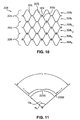
- the force f required to bend tubular stent 2000 of a particular length into a given arc having a central angle and a given arc radius is a measure of the stent flexibility.
- a measure of the "kink resistance" of a stent is the kink angle ⁇ k or kink radius R k at which the stent kinks (when the tubular configuration becomes disrupted by crease 2200 as shown in Fig. 11).
- the stent architecture having a lesser kink radius and a greater kink angle has the most kink resistance.
- radial strength can be described generally as the resistance of a stent to radial compression.
- a stent with more radial strength exerts a greater outward radial force when compressed than does a stent with less radial strength.
- a shape memory expandable or resiliently compressible stent may have a fully expanded diameter and a constrained diameter as deployed within a lumen.
- the fully expanded diameter is the diameter to which the stent would expand without any constraint.
- radial strength can be expressed in terms of radial force or radial pressure.
- radial force is a valid measure of radial strength. If one stent has a different surface area than the other, however, then radial pressure is a more appropriate measure of radial strength, so that the surface area of the stent is not a factor in the comparison.
- stent architecture refers to the various structural elements that comprise the stent construction.
- There are general categories of architecture such as for example, wound stent architecture, braided stent architecture, laser cut tube stent architecture, filamentary stent architecture, polygonal cell stent architecture, or zig-zag stent architecture.
- the various categories of stent architecture may overlap one another. For instance, one stent may comprise a filamentary, wound, polygonal cell stent architecture, whereas another stent may comprise a laser cut tube, polygonal cell stent architecture.
- “Filamentary” indicates that a stent comprises one or more filaments formed into the stent architecture
- a “laser cut tube” indicates that the stent comprises a tube that has been cut by a laser to form the geometric elements.
- stent architecture One component of stent architecture is geometric configuration.
- the "geometric configuration" refers to the geometric shape of the elements created within the stent.
- a stent having a filamentary, wound, polygonal cell stent architecture may have a geometric configuration wherein the cells are hexagonal and have a first size.
- Another stent having hexagonal cells of a second size still has the same geometric configuration as the stent having the hexagonal cells of the first size, but may still be said to have a different stent architecture.
- manipulator property is used herein to designate any one or more of these properties to facilitate discussion of this invention. Additionally, examples of different regions having different manipulation properties are discussed herein primarily in terms of variation in flexibility or stiffness. It should be understood, however, that whereas one stent region with respect to another may be characterized for brevity and convenience herein with respect only to differing stiffness, that region may also have a different radial strength and/or kink resistance as well.
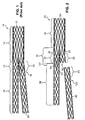
- stent 20 is a modular bifurcated stent essentially identical to the stent shown in Fig. 1 except for a modification according to the present invention.
- Stent 20 shown in its unassembled configuration, has two modular components: bifurcated component 30 and modular leg component 40.
- Bifurcated component 30 comprises a trunk section 32, a branching section 34 and a fixed leg section 38.
- Branching section 34 has a first branch 33 comprising a socket 35 and a second branch 36 comprising a fixed leg interface 37, from which fixed leg section 38 depends.
- the assembled configuration of the stent 20 similar to the assembled configuration of stent 10 shown in Fig.
- mating portion 23 of modular leg component 40 inserts into socket 35, creating a stiff, overlap in region 22.
- overlap region 22 is not shown in an assembled configuration (with mating portion 23 of leg 40 inserted in socket 35) in Fig. 2, it should be understood that any reference herein to overlap region 22 and properties thereof refer to overlap region 22 in the assembled configuration of modular stent 20 (which resembles the assembled configuration of stent 10 shown in Fig. 1).
- Modular leg component 40 may mate with socket 35 in any known way to create such an overlap 22.
- Trunk section 32 and fixed leg section 38 comprise relatively flexible regions that are less stiff than overlap region 22.
- fixed leg interface 37 of stent 20 comprises a reinforced region that mimics the manipulation properties of overlap region 22 in accordance with the present invention.
- the purpose of reinforcing fixed leg interface 37 is to provide essentially the same manipulation properties in both the reinforced region and in the overlap region 22, it should be understood that in practice, due to variations in materials, assembly, or other factors, the actual manipulation properties of the overlap region and reinforced region may not be exactly the same.
- the manipulation properties of the two regions are "essentially equivalent" as claimed herein, however, in that fixed leg interface 37 reacts to loading in the same manner as overlap region 22.
- fixed leg interface 37 being essentially equivalent to overlap region 22 means that whatever slight differences may remain between the two regions, these differences are not significant enough to cause kinking merely as a result of any mismatch between the manipulation properties of the two sides.
- fixed leg interface 37 comprises reinforcing material attached to stent 20 in the form of an overlapping stent 50.
- reinforcing material shown in Fig. 2 comprises a discrete overlapping stent 50 having filaments 52 arranged in a pattern similar to overlap region 22, in an alternative embodiment the stiffening filaments 52 attached to stent 20 may be individual filaments rather than forming a discrete and separate stent. Other means for stiffening a region to mimic another region may also be used, as are described below.
- regions 137 and 123 just below interface 37 on leg 38 and mating portion 23 on leg 40, respectively, as shown in Fig. 2 become the next regions most likely to kink.
- the invention may further comprise regions 137 and 123 that have a greater stiffness than the remainder of leg 38 and leg 40, respectively, to prevent kinking in those regions.
- the stiffening in regions 137 and 123 may be effected by any of the methods discussed herein below.
- non-bifurcated modular stents also have overlap regions that may benefit from providing a mimic region elsewhere in the stent to match the manipulation properties of the overlapping region of the stent.
- Many stent embodiments have multiple regions with different manipulation properties, such as higher radial strength sections at the ends of a stent, that do not necessarily mimic other regions of the stent. Regardless of how or why such regions are created, another aspect of this invention addresses the discontinuity of manipulation properties that arises between adjacent stiff and flexible regions.
- stiffened region 137 on leg 38 may thus be a transition region of intermediate stiffening between the relatively greater stiffening desired for fixed leg interface 37 to mimic overlap region 22 and the normal flexibility of the remainder of leg 38.
- Stiffened region 123 therefore essentially mimics transition region 137, as region 123 stands alone without any corresponding region of greater stiffness on leg 40 to transition from, as the greater stiffness in overlap region 22 arises only after mating portion 23 is inserted in socket 35. Accordingly, region 123 may be referred to as a "transition mimic" region.
- the invention encompasses any stent having a transition region at an interface between regions of differing manipulation properties, such as a transition region between a stiff region and a flexible region to provide an intermediate stiffness, including a stiffness gradient.
- the transition region may comprise any of the various means for providing a transition, as disclosed herein.
- the invention includes providing kink resistance to a stent having regions of different manipulation properties by providing a transition region between the different regions.
- One means of providing regions having different manipulation properties within a stent is to provide regions having different metallurgical properties.
- metallurgical property shall have its common meaning, namely a characteristic of a metal including both how the metal was made and its physical and chemical characteristics. Different metallurgical properties, as used herein, are sufficiently different such that some measurable difference in manipulation properties can be seen in a typical use of the prosthesis of the present invention.
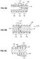
- a stiff region 126 of stent 100 may receive a localized heat treatment, such as from a beam 101 of laser device 102, that modifies the metallurgical properties in the stiff region to make it stiffer than the metallurgical properties in remaining flexible region 124.
- a high-power laser such as a continuous wave YAG or CO 2 laser
- a temperature between 100°C and the melting point of the alloy controlled by varying the power of the beam and the exposure time (for example, on the order of approximately 1 second), may be sufficient to create the desired modification in metallurgical properties.
- Another method of providing different metallurgies to different regions is to anneal each region using different amounts of thermal input, thus providing a different annealing history for each region.
- stent 100 comprises a nitinol stent
- the annealing history of the metal sets the material and shape memory properties of the stent, as is well known.
- the different annealing histories may be provided in any number of ways, three exemplary methods of which are described herein.
- the effect of the annealing process on the wire of the stent is dependent upon the product of temperature and time, referred to herein as the "thermal input".
- the thermal input typically takes the form of a time integral of temperature.
- the thermal input necessary to create the desired properties in a wire is dependent upon the material composition of the wire, the diameter of the wire, and the cold-working or strain history of the wire. Accordingly the precise temperatures and times of exposure vary depending upon the pre-annealed and desired annealed properties of the wire, but are known by those skilled in the art for specific wire grades commonly used and are readily determinable for new wire grades by experimentation.
- a zoned annealing furnace 150 such as is well-known in the art, is used to provide a relatively hotter region 152 and a relatively cooler region 154, as illustrated by the temperature/position curve shown in graph 170.
- Stent 100 is annealed on mandrel 160 by exposing flexible region 124 of the stent to relatively hotter region 152 of furnace 150 and exposing stiff region 126 of the stent to relatively cooler region 154 of the furnace. Annealing stent 100 for a predetermined amount of time with such exposures thus provides flexible region 124 with a greater thermal input than stiff region 126.
- stent 100 further comprises a transition region 125 having a gradient of metallurgical properties from flexible region 124 to mimic region 126.
- a 3-zone tube furnace marketed by Carbolite of Sheffield, England, can supply up to three different temperature zones, each 200 mm long, with a maximum differential of 30°C between each pair of adjacent zones. A 30°C temperature differential is sufficient to produce desired differences in manipulation properties across corresponding regions in the stent and gradient intermediate properties between the regions.
- a stent according to the present invention may be made with as many different zones as can be supplied by the annealing furnace, including more than 3 zones.
- FIG. 6A another method of providing a different annealing history for the stiff region 126 versus the flexible region 124, is to provide a hollow mandrel 170 that has a high heat sink region 172 and a low heat sink region 174.
- High heat sink region 172 has a relatively higher thermally conductive mass per unit length than low heat sink region 174.
- high heat sink region 172 may comprise a region having a greater cross-sectional mass than the low heat sink region 174.
- High heat sink region 172 of the mandrel 170 is co-located with stiff region 126 of stent 100 and low heat sink region 174 of mandrel 170 is co-located with flexible region 124 of the stent.
- Transition region 173 between the cross-sectional mass in the high heat sink region and the cross-sectional mass in the low heat sink region may comprise a gradual change in cross section to provide a thermal input gradient and a corresponding gradient of metallurgical properties in transition region 125 of stent 100.
- region 1172 of mandrel 1170 may have a higher thermal conductivity (greater specific heat capacity) than region 1174.
- region 1172 may be metal and region 1174 may be ceramic.
- the greater thermal conductivity of region 1172 as compared to region 1174 of mandrel 170 subjects flexible region 124 of stent 100 to a greater thermal input than stiff region 126, which creates the difference in annealed stiffness.
- the greater thermal conductivity allows a faster heat-up time and thus a greater time integral of temperature.
- stainless steel (alloy 304 SS) has a thermal conductivity of approximately 16 W/mK (Watts per meter per degree Kelvin), aluminum has a conductivity of approximately 147 W/mK, and toughened zirconia ceramic has a conductivity of approximately 2 W/mK.
- Mandrel 1170 thus may comprise a mix of adjacent ceramic and metallic regions.
- a threaded fitting or adhesively-bonded post 1175 may be provided at the interface between the regions, thus creating a transition region 1173 having an intermediate thermal conductivity that creates transition region 125 in stent 100.
- another material with an intermediate thermal conductivity could be used in the transition region.
- the geometry of post 1175 (or omission of the post altogether) may be manipulated as desired to tailor the thermal conductivity in the transition region between that of a step change and a gradient.
- a collar 175 of ceramic material may be placed over stiff region 126 of the stent on an all-metallic mandrel 177 during annealing, shielding the stent wire in stiff region 126 from some of the heat of the annealing furnace (or other annealing heat source known in the art).
- Collar 175 may have a variable thickness to provide a transition region 125 between flexible region 124 and stiff region 126.
- the variable thickness may be in the form of a gradient thickness as shown in Fig. 6C, or may comprise a step change in thickness.
- different collars having different thicknesses and/or different thermal conductivities may be used for the stiff region 126 and the transition region 125.
- the transition region may in the alternative be provided using multiple collars having different thicknesses and/or materials of construction or gradients thereof.
- wire 202 in flexible region 224 may have a smaller diameter d 1 than wire 204 in the stiff region 226 having a diameter d 2 .
- the metal left between the laser-cut slots may be thicker in the stiff region than in the flexible region.
- elongated stent 60 for holding open designated portion 62 of body lumen 64 having curved regions 66.
- Designated portion 62 has a length L 1 .
- Stent 60 has an expanded configuration for deployment within the body lumen as shown in Fig. 8, a compressed configuration (not shown) for introduction and transport within the lumen prior to deployment as is well-known in the art, and a length equivalent to length L 1 .
- Stent 60 has relatively stiff regions 68 and relatively flexible regions 70, each of the flexible regions positioned to align with one of the curved regions 66 of the body lumen 64 when stent 60 is deployed.
- relatively flexible regions 70 may be tailored by reducing the cross sectional area of the stent or by providing a higher annealing temperature, rather than tailoring relatively stiff regions 68 by increasing the cross-sectional area or providing a lower annealing temperature.
- Modifying stent architecture may also be used for providing regions of different manipulation properties within a stent to mimic another region of the stent and/or to provide kink resistance.
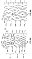
- the stent may have a stent architecture comprising a recurrent pattern of geometric elements -- struts 302 connected at apex sections 304 to form zigs 306 and zags 307, each zig comprising apex section 304i and the top half of connected struts 302i pointing in one direction (down, as shown in Fig.
- each zag comprising an apex section 304a and the bottom half of connected struts 302a pointing in the opposite direction (up, as shown in Fig. 9A).
- the elements are arranged in circumferential hoops 308 axially attached to one another.
- a hoop in a helical winding pattern may comprise one 360° helical revolution of the wire about the stent.
- Each zig in hoop 308f of flexible section 324 as shown in Fig. 9A has a zig height H F .
- Each hoop 308f has three zigs per hoop.
- Stiff region 326 has hoops 308s having a zig height H S that is less than zig height H F and having six zigs 306s per hoop.
- Transition region 352 provides a gradient of manipulation properties between flexible region 324 and stiff region 326 by providing zigs of an intermediate zig height, namely in a gradient from Ht 1 in hoop 308t 1 to Ht 2 in hoop 308t 2 , and by providing an intermediate number of elements in each hoop, namely 4 zigs in hoop 308t 1 and 5 zigs in hoop 308t 2 .
- Fig. 9A with both the height and number of zigs varied from the flexible to the stiff region, alternate embodiments may vary only a single variable, such as is shown in Fig. 9B.
- the included angle ⁇ between adjacent struts 302 also varies from hoop to hoop.
- the included angle ⁇ r in hoops 1308f is greater than the included angle ⁇ t in hoop 1308t which, in turn, is greater than the included angle ⁇ s in hoops 1308s.
- the included angle is another variable that may be varied, not only with respect to continuous wire zig-zag elements as illustrated in Figs. 9A and 9B, but also with respect to elements of other stent architectures as well, such as laser-cut tubular stent architectures. Where both the zig height and zig number are varied, as shown in Fig. 9A, the included angle may or may not vary, depending upon the specific variation of zig height and zig number.
- One or more zigs 306 in each hoop 308 may be connected to an axially adjacent hoop 308, such as with a suture 309 as shown in Fig. 10.
- a weld, an adhesive bond, or any means known in the art for joining axially adjacent elements may be provided.
- hoop 308f in flexible region 324 of Fig. 10 only one zig 306f is axially connected to a zag 307f of the axially adjacent hoop, providing a ratio of 1:3 connected to unconnected zigs (25% connected zigs) in the flexible region.
- stiff region 326 100% of the zigs are connected.
- Transition region 352 provides a stiffness gradient between flexible region 324 and stiff region 326 by providing an intermediate ratio of connected to unconnected elements, namely a ratio gradient comprising 2:2 in hoop 308t 1 and 3:1 in hoop 308t 2 .
- a single stent embodiment may incorporate variations of any combination of the above variables.
- a zig-zag wire stent architecture other stent architectures having elements with a different geometry may comprise regions of different size elements, different numbers of elements per hoop, different angles between structural members, or different ratios of connected elements, to provide similar variations in manipulation properties.
- the stiff and the flexible regions have the same general stent geometry. That is, although certain features of the architecture may be changed, such as zig height, number of zigs, or ratio of connected to unconnected zigs, the general zig-zag geometry is still maintained.
- other stent designs such as those described in application 09/442,165, filed on November 16, 1999, assigned to the common assignee of this invention, and published as WO01/35864 on May 25, 2001, two entirely different filamentary stent geometries may be linked together, such as a braided stent geometry and a zig-zag stent geometry. Each geometry has respective manipulation properties, and thus the interface between regions of different geometry, in certain configurations, may present a distinct step change.
- the present invention of providing a transition region between a relatively stiff and a relatively flexible region may be incorporated into such a design, such as by attaching wires as force bridges between the different stent geometry regions.
- the "diamond stent" 3000 described in the Colgan Application comprises a pattern of diamond-shaped elements 3002.
- the Colgan Application also discloses box nodes 3004 that may be placed at one or more interfaces 3006 between adjacent diamond elements.
- box nodes 3004 may be used for providing local stiffness in one region as compared to another, such as greater stiffness at the ends than in the middle.
- Interfaces 3006 without box nodes comprise "empty interfaces" 3007.
- the present invention of modifying the stent architecture to provide a transition region between areas of different stiffness may be applied to the invention described in the Colgan Application, as may the present invention of providing a stiffened region to mimic another region of a stent.
- a transition region 3010 may contain an intermediate ratio of box nodes to empty interfaces or a gradient in the ratio.
- region 3008 has a box node at every circumferential interface 3006, or a ratio of 4:0 box nodes to empty interfaces 3007, whereas region 3009 has only one box node per circumferential revolution, or a ratio of 1:3 box nodes to empty interfaces.
- Transition region 3010 contains an intermediate ratio of box nodes 3004 to empty interfaces 3007 in the form of a gradient of 3:1 to 2:2 box nodes to empty interfaces between from region 3008 with an infinite ratio and region 3009 with a 1:3 ratio.
- Region 3008 may be a mimic region that is stiffened using box nodes to provide stiffness and/or other manipulation properties that are essentially equivalent to the stiffness and/or other manipulation properties of another region of the stent.
- the Pinchuk patent describes a process for coating a stent with a polymer such that crossing or adjacent wire filaments are bound to each other by the polymer without the polymer occluding interstices between the filaments.
- the polymer is applied to the stent in a plurality of spray coatings, wherein an increase in the number of spray coatings increases the radial strength of the stent.
- the Pinchuk patent may be applied to selected sections of a stent to create stiffened regions and more flexible regions by applying the polymer coating in the stiff regions and no coating (or a lesser number of spray coats) in the flexible regions.
- the Pinchuk patent may further be applied to create transition regions between the relatively stiff and flexible regions by applying an intermediate number of spray coatings to the transition region between the flexible and stiff regions.
- a gradient transition region may be provided by creating a gradient number of coatings.
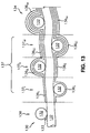
- stiffened region 134 comprises four layers of polymer coating 136i-iv, whereas flexible region 138 comprises no coating layers.
- Transition region 137 comprises an intermediate number of layers of polymer coating from one layer 136i to three layers 136i-iii. Such layers may be applied by masking the region of the stent not to be coated during spray coating of each region.
- the polymer stiffening method of stiffening is particularly advantageous for stiffening braided stents or for affixing adjacent apices of zig-zag stents as disclosed in the Pinchuk patent
- the polymer stiffening method may be applied to any stent architecture known in the art having overlapping, touching, or nearly-touching filaments desired to be bonded together with some degree of stiffness.
- the polymer coating is applicable to stents having only near-contact points, a near-contact point being defined as a point where stent filaments do not actually cross or contact one another, but are close enough that the polymer can bridge the distance between the filaments.
- filamentary stent architectures have some degree of interstitial space defined by the filaments.
- the interstitial space may be in the form of discrete closed cells bounded on all sides by filamentary structure, or a continuous open space connected by the gaps between near-contact points.
- the polymer coating method of the present invention does not substantially occlude the interstitial space. That is, a majority of the interstitial space still remains after the coating process, even if the coating process may segment a formerly continuous open space into discrete cells by closing gaps between near-contact points.
Landscapes
- Health & Medical Sciences (AREA)
- Engineering & Computer Science (AREA)
- Biomedical Technology (AREA)
- Heart & Thoracic Surgery (AREA)
- Life Sciences & Earth Sciences (AREA)
- Cardiology (AREA)
- Oral & Maxillofacial Surgery (AREA)
- Transplantation (AREA)
- Veterinary Medicine (AREA)
- Vascular Medicine (AREA)
- Public Health (AREA)
- Animal Behavior & Ethology (AREA)
- General Health & Medical Sciences (AREA)
- Optics & Photonics (AREA)
- Physics & Mathematics (AREA)
- Media Introduction/Drainage Providing Device (AREA)
- Prostheses (AREA)
Abstract
Description
Claims (35)
- A modular elongated stent for holding open a body lumen and for assembly in situ, the stent (20) comprising at least a first component (30) and a second component (40), the stent having an assembled configuration comprising the first component and the second component assembled together, the stent comprising:an overlap region (22) in the first component adapted to receive a portion of the second component in the assembled configuration, the overlap region having a first set of manipulation properties in the assembled configuration;one or more flexible regions (32, 38; 24; 124; 224; 324; 3309; 138) attached to the overlap region, each flexible region having a second set of manipulation properties different than the first set of manipulation properties, the second set of manipulation properties including at least one of: greater flexibility, greater kink resistance, or less radial strength than the first set of manipulation properties; anda mimic region (37; 26; 126; 226; 326; 3008; 134) attached to the flexible regions the mimic region having a third set of manipulation properties that is essentially equivalent to the first set of manipulation properties.
- The stent of claim 1 wherein the flexible region (124) has first metallurgical properties and the mimic region (126) has second metallurgical properties that are different than the first metallurgical properties.
- The stent of claim 2 wherein the first metallurgical properties are caused by a first annealing history and the second metallurgical properties are caused by a second annealing history.
- The stent of claim 1 wherein the flexible region (224) comprises structural elements (202) having a cross-sectional area and the mimic region (226) comprises structural elements (204) having a cross-sectional area larger than in the flexible region.
- The stent of claim 1 wherein the mimic region comprises reinforcing material (50; 54) attached to the stent.
- The stent of claim 5 wherein the reinforcing material comprises an overlapping stent (50).
- The stent of claim 5 wherein the reinforcing material comprises one or more stiffening filaments (54).
- The stent of claim 1 wherein the modular stent comprises a bifurcated modular stent wherein:wherein the overlap region (22) comprises the socket (35), the assembled configuration comprises the mating portion (23) of the modular leg component (40) inserted in the socket (35), the mimic region (37) comprises the fixed leg interface (37), and the flexible regions (32; 38) comprise the trunk section (32) and the fixed leg section (38).the first component (30) comprises a bifurcated component (30) comprising a trunk section (32), a bifurcated section (34) attached to the trunk section (32) and having a first branch (33) comprising a socket (35) and a second branch (36) comprising a fixed leg interface (37), and a fixed leg section (38) depending from the fixed leg interface (37), andthe second component (40) comprises a modular leg component (40) having a mating portion (23) adapted for mating with the socket (35),
- The stent of claim 8 further comprising a transition region (137) between the fixed leg (38) and the fixed leg interface (37) and a transition mimic region (123) in the modular leg component (40) adjacent the mating portion (23), the transition region (137) comprising an intermediate set of manipulation properties between the second set of manipulation properties and the third set of manipulation properties and the transition mimic region (123) comprising a fourth set of manipulation properties essentially equivalent to the intermediate set of manipulation properties.
- The stent of claim 1 further comprising a transition region (137; 52; 125; 252; 352; 3010; 137 between the flexible region and the mimic region, the transition region comprising an intermediate set of manipulation properties between the second set of manipulation properties and the third set of manipulation properties.
- The stent of claim 9 wherein the transition region (137) comprises a gradient of manipulation properties from the second set of manipulation properties to the third set of manipulation properties.
- The stent of claim 1 wherein the overlap region (22) has a first stiffness, the flexible region (32, 38; 24, 124; 224; 324; 3009; 138) has a second stiffness less than the first stiffness, and the mimic region (37; 26; 126; 226; 326; 326; 3008; 134) has a third stiffness essentially equivalent to the first stiffness, the stent further comprising a transition region (137; 52; 125; 252; 352; 3010; 137) between the flexible region and the mimic region, the transition region comprising an intermediate stiffness greater than the second stiffness and less than the third stiffness.
- The stent of claim 12 wherein the transition region (137; 52; 125; 252; 352; 3010; 137) comprises a stiffness gradient from the second stiffness to the third stiffness.
- The stent of claim 11 wherein the transition region (137; 52) comprises a bridging material (50;54) attached to the stent between the mimic region and the flexible region.
- The stent of claim 14 wherein the bridging material comprises one or more wires attached to the stent.
- The stent of claim 11 wherein the mimic region (126) has different metallurgical properties than the flexible region (124) and the transition region (125) comprises a gradient of metallurgical properties from the flexible region to the mimic region.
- The stent of claim 1 wherein the mimic region (326; 3008) comprises a region of different stent architecture relative to the flexible region (324; 3009).
- The stent of claim 17 wherein the stent architecture of the flexible region (324) comprises a geometry having a recurrent pattern of geometric elements in an arrangement of circumferential hoops (308) axially attached to one another, one or more elements of each hoop comprising connected elements that are connected to an axially adjacent hoop, any elements not connected to an axially adjacent hoop being unconnected elements, each element having an element height and an included angle, each hoop comprising a number of elements and a ratio of connected elements to unconnected elements, the mimic region (326) and the flexible region (324) differing in stent architecture by one of: the element height, the number of elements in each hoop, the included angle, the ratio of connected to unconnected elements, or a combination thereof.
- The stent of claim 18 further comprising a transition region (352) between the flexible region and the mimic region, the transition region comprising a gradient from the second set of manipulation properties to the third set of manipulation properties, wherein said transition region comprises one of: an intermediate element height, an intermediate number of elements in each hoop, an intermediate included angle, an intermediate ratio of connected to unconnected elements, or a combination thereof.
- The stent of claim 17 wherein the stent architecture of the flexible region (3009) comprises a geometry having a recurrent pattern of diamond-shaped elements in an arrangement of circumferential hoops axially attached to one another, each diamond-shaped element having an interface with at least one other diamond-shaped element, at least one interface comprising a box node (3004), interfaces without a box node comprising an empty interface (3007), each definable region of the stent having a ratio of box nodes to empty interfaces, the mimic region (3008) and the flexible region (3009) differing in stent architecture by the ratio of box nodes to empty interfaces in each region.
- The stent of claim 20 further comprising a transition region (3010) between the flexible region (3009) and the mimic region (3008), the transition region comprising a gradient from the second set of manipulation properties to the third set of manipulation properties, wherein said transition region comprises one of: an intermediate ratio of box nodes to empty interfaces, a gradient of ratios of box nodes to empty interfaces, or a combination thereof.
- A method for providing kink resistance in a modular elongated stent adapted to hold open a body lumen and for assembly in situ, the stent (20) comprising at least a first component (30) and a second component (40), the stent having an assembled configuration comprising the first component and the second component assembled together, the stent having at least one overlap region (22) in the first component adapted to receive a portion (23) of the second component in the assembled configuration and one or more flexible regions (32) attached to the overlap region, the overlap region having a first set of manipulation properties and the flexible region having a second set of manipulation properties different than the first set of manipulation properties, the second set of manipulation properties including at least one of: greater flexibility, greater kink resistance, or less radial strength than the first set of manipulation properties, the method comprising:providing a mimic region (37; 26; 126; 226; 326; 3008; 134) attached to the flexible region, the mimic region having a third set of manipulation properties essentially equivalent to the first set of manipulation properties.
- The method of claim 22 wherein providing the mimic region comprises modifying the mimic region relative to the flexible region by one of: modifying the metallurgical properties, providing members having a larger cross-sectional area, attaching reinforcing material, modifying the stent architecture, applying a polymer coating, or a combination thereof.
- The method of claim 23 wherein modifying the metallurgical properties comprises heat treating the mimic region.
- The method of claim 24 wherein the heat treating step comprises local laser heat treating.
- The method of claim 23 wherein modifying the metallurgical properties comprises providing a different annealing history for the mimic region.
- The method of claim 26 wherein providing the different annealing history for the mimic region comprises:a) providing a zoned annealing furnace (150) having a relatively hotter region (152) with a first temperature and a relatively cooler region (154) with a second temperature less than the first region; andb) annealing the stent by exposing the flexible region of the stent to the relatively hotter region and exposing the stiff region of the stent to the relatively cooler region.
- The method of claim 26 wherein providing the different annealing history for the mimic region comprises:a) mounting the stent on a mandrel (170) during annealing, the mandrel having a relatively high heat sink region (172) and a relatively low heat sink region (174), the relatively high heat sink region of the mandrel co-located with the stiff region of the stent; and the relatively low heat sink region of the mandrel co-located with the flexible region of the stent; andb) providing with the relatively high heat sink region a longer heat-up time for the stiff region than the relatively low heat sink region provides for the flexible region during annealing, so that the flexible region experiences a greater thermal input than the stiff region.
- The method of claim 28 further comprising fabricating the mandrel such that the relatively high heat sink region has greater cross-sectional mass than the relatively low heat sink region.
- The method of claim 26 wherein providing the different annealing history for the mimic region comprises:a) mounting the stent on a mandrel (1170) during annealing, the mandrel having a relatively high thermal conductivity region (1172) and a relatively low thermal conductivity region (1174), the relatively high thermal conductivity region of the mandrel co-located with the stiff region of the stent; and the relatively low thermal conductivity region of the mandrel co-located with the flexible region of the stent; andb) providing with the relatively high thermal conductivity region a longer heat-up time for the stiff region than the relatively low thermal conductivity region provides for the flexible region during annealing, so that the flexible region experiences a greater thermal input than the stiff region.
- The method of claim 30 further comprising fabricating the mandrel such that the relatively high thermal conductivity region comprises a metal and the relatively low thermal conductivity region comprises a ceramic.
- The method of claim 26 wherein providing the different annealing history for the mimic region comprises:a) mounting the stent on a mandrel (177) having a relatively high thermal conductivity;b) covering the stiff region with a collar (175) of a relatively low thermal conductivity material; andc) annealing the stent using a heat source such that the collar shields the stiff region from the heat source so that the flexible region experiences a greater thermal input than the stiff region.
- The method of claim 32 further comprising fabricating the mandrel such that the mandrel comprises a metal and the collar comprises a ceramic.
- The method of claim 23 wherein attaching reinforcing material comprises attaching one or more stiffening filaments (54).
- The method of claim 23 wherein attaching reinforcing material comprises attaching an overlapping stent (50).
Applications Claiming Priority (3)
| Application Number | Priority Date | Filing Date | Title |
|---|---|---|---|
| US442192 | 1989-11-28 | ||
| US09/442,192 US6610087B1 (en) | 1999-11-16 | 1999-11-16 | Endoluminal stent having a matched stiffness region and/or a stiffness gradient and methods for providing stent kink resistance |
| PCT/US2000/031374 WO2001035863A1 (en) | 1999-11-16 | 2000-11-16 | Modular endoluminal stent having matched stiffness regions |
Publications (2)
| Publication Number | Publication Date |
|---|---|
| EP1229863A1 EP1229863A1 (en) | 2002-08-14 |
| EP1229863B1 true EP1229863B1 (en) | 2004-09-22 |
Family
ID=23755871
Family Applications (1)
| Application Number | Title | Priority Date | Filing Date |
|---|---|---|---|
| EP00978682A Expired - Lifetime EP1229863B1 (en) | 1999-11-16 | 2000-11-16 | Modular endoluminal stent having matched stiffness regions |
Country Status (7)
| Country | Link |
|---|---|
| US (3) | US6610087B1 (en) |
| EP (1) | EP1229863B1 (en) |
| JP (1) | JP2003513747A (en) |
| AU (1) | AU776435B2 (en) |
| CA (1) | CA2386946A1 (en) |
| DE (1) | DE60014149T2 (en) |
| WO (1) | WO2001035863A1 (en) |
Cited By (6)
| Publication number | Priority date | Publication date | Assignee | Title |
|---|---|---|---|---|
| US9545263B2 (en) | 2014-06-19 | 2017-01-17 | Limflow Gmbh | Devices and methods for treating lower extremity vasculature |
| US10543308B2 (en) | 2017-04-10 | 2020-01-28 | Limflow Gmbh | Methods for routing a guidewire from a first vessel and through a second vessel in lower extremity vasculature |
| US11116943B2 (en) | 2018-10-09 | 2021-09-14 | Limflow Gmbh | Methods for accessing pedal veins |
| US11446170B2 (en) | 2004-09-08 | 2022-09-20 | Limflow Gmbh | Minimally invasive surgical apparatus and methods |
| US11612397B2 (en) | 2019-11-01 | 2023-03-28 | Limflow Gmbh | Devices and methods for increasing blood perfusion to a distal extremity |
| US12096938B2 (en) | 2023-03-24 | 2024-09-24 | Limflow Gmbh | Devices and methods for increasing blood perfusion to a distal extremity |
Families Citing this family (86)
| Publication number | Priority date | Publication date | Assignee | Title |
|---|---|---|---|---|
| US6258116B1 (en) * | 1996-01-26 | 2001-07-10 | Cordis Corporation | Bifurcated axially flexible stent |
| US7238197B2 (en) | 2000-05-30 | 2007-07-03 | Devax, Inc. | Endoprosthesis deployment system for treating vascular bifurcations |
| US8728143B2 (en) | 1996-06-06 | 2014-05-20 | Biosensors International Group, Ltd. | Endoprosthesis deployment system for treating vascular bifurcations |
| US7686846B2 (en) | 1996-06-06 | 2010-03-30 | Devax, Inc. | Bifurcation stent and method of positioning in a body lumen |
| US6240616B1 (en) | 1997-04-15 | 2001-06-05 | Advanced Cardiovascular Systems, Inc. | Method of manufacturing a medicated porous metal prosthesis |
| US10028851B2 (en) | 1997-04-15 | 2018-07-24 | Advanced Cardiovascular Systems, Inc. | Coatings for controlling erosion of a substrate of an implantable medical device |
| US8172897B2 (en) | 1997-04-15 | 2012-05-08 | Advanced Cardiovascular Systems, Inc. | Polymer and metal composite implantable medical devices |
| US7807211B2 (en) * | 1999-09-03 | 2010-10-05 | Advanced Cardiovascular Systems, Inc. | Thermal treatment of an implantable medical device |
| US6325822B1 (en) | 2000-01-31 | 2001-12-04 | Scimed Life Systems, Inc. | Braided stent having tapered filaments |
| US6805898B1 (en) * | 2000-09-28 | 2004-10-19 | Advanced Cardiovascular Systems, Inc. | Surface features of an implantable medical device |
| US8372139B2 (en) | 2001-02-14 | 2013-02-12 | Advanced Bio Prosthetic Surfaces, Ltd. | In vivo sensor and method of making same |
| US6660034B1 (en) * | 2001-04-30 | 2003-12-09 | Advanced Cardiovascular Systems, Inc. | Stent for increasing blood flow to ischemic tissues and a method of using the same |
| US6695920B1 (en) | 2001-06-27 | 2004-02-24 | Advanced Cardiovascular Systems, Inc. | Mandrel for supporting a stent and a method of using the mandrel to coat a stent |
| US6565659B1 (en) * | 2001-06-28 | 2003-05-20 | Advanced Cardiovascular Systems, Inc. | Stent mounting assembly and a method of using the same to coat a stent |
| US7147661B2 (en) | 2001-12-20 | 2006-12-12 | Boston Scientific Santa Rosa Corp. | Radially expandable stent |
| US7029494B2 (en) * | 2002-02-08 | 2006-04-18 | Scimed Life Systems, Inc. | Braided modular stent with hourglass-shaped interfaces |
| US7004964B2 (en) * | 2002-02-22 | 2006-02-28 | Scimed Life Systems, Inc. | Apparatus and method for deployment of an endoluminal device |
| US7887573B2 (en) * | 2002-02-22 | 2011-02-15 | Boston Scientific Scimed, Inc. | Method and apparatus for deployment of an endoluminal device |
| US7396539B1 (en) * | 2002-06-21 | 2008-07-08 | Advanced Cardiovascular Systems, Inc. | Stent coatings with engineered drug release rate |
| US7335265B1 (en) * | 2002-10-08 | 2008-02-26 | Advanced Cardiovascular Systems Inc. | Apparatus and method for coating stents |
| JP2006505309A (en) | 2002-11-08 | 2006-02-16 | ジャック スガン、 | Endoprosthesis for vascular bifurcation |
| US7704276B2 (en) * | 2002-11-15 | 2010-04-27 | Synecor, Llc | Endoprostheses and methods of manufacture |
| US7074276B1 (en) | 2002-12-12 | 2006-07-11 | Advanced Cardiovascular Systems, Inc. | Clamp mandrel fixture and a method of using the same to minimize coating defects |
| US7025779B2 (en) | 2003-02-26 | 2006-04-11 | Scimed Life Systems, Inc. | Endoluminal device having enhanced affixation characteristics |
| US20040225349A1 (en) * | 2003-05-09 | 2004-11-11 | Thistle Robert C. | Eversible locking mechanism for modular stents |
| US20040254628A1 (en) * | 2003-06-13 | 2004-12-16 | Patrice Nazzaro | One-branch stent-graft for bifurcated lumens |
| US20050118344A1 (en) * | 2003-12-01 | 2005-06-02 | Pacetti Stephen D. | Temperature controlled crimping |
| US7198675B2 (en) | 2003-09-30 | 2007-04-03 | Advanced Cardiovascular Systems | Stent mandrel fixture and method for selectively coating surfaces of a stent |
| US7704544B2 (en) * | 2003-10-07 | 2010-04-27 | Advanced Cardiovascular Systems, Inc. | System and method for coating a tubular implantable medical device |
| US7763011B2 (en) * | 2003-12-22 | 2010-07-27 | Boston Scientific Scimed, Inc. | Variable density braid stent |
| WO2005089674A1 (en) * | 2004-03-15 | 2005-09-29 | Medtronic Vascular Inc. | Radially crush-resistant stent |
| WO2006024489A2 (en) | 2004-08-30 | 2006-03-09 | Interstitial Therapeutics | Methods and compositions for the treatment of cell proliferation |
| US7892592B1 (en) | 2004-11-30 | 2011-02-22 | Advanced Cardiovascular Systems, Inc. | Coating abluminal surfaces of stents and other implantable medical devices |
| US9427340B2 (en) | 2004-12-14 | 2016-08-30 | Boston Scientific Scimed, Inc. | Stent with protruding branch portion for bifurcated vessels |
| AU2006210494B2 (en) | 2005-02-04 | 2011-01-06 | Ams Research Corporation | Needle design for male transobturator sling |
| US20060217760A1 (en) * | 2005-03-17 | 2006-09-28 | Widomski David R | Multi-strand septal occluder |
| US20060259127A1 (en) * | 2005-05-10 | 2006-11-16 | Deborah Tolomeo | Apparatus and method for anchoring endoluminal prostheses in tortuous geometries |
| US7823533B2 (en) | 2005-06-30 | 2010-11-02 | Advanced Cardiovascular Systems, Inc. | Stent fixture and method for reducing coating defects |
| US7735449B1 (en) | 2005-07-28 | 2010-06-15 | Advanced Cardiovascular Systems, Inc. | Stent fixture having rounded support structures and method for use thereof |
| US20070129791A1 (en) * | 2005-12-05 | 2007-06-07 | Balaji Malur R | Stent with integral filter |
| US7867547B2 (en) | 2005-12-19 | 2011-01-11 | Advanced Cardiovascular Systems, Inc. | Selectively coating luminal surfaces of stents |
| US8069814B2 (en) | 2006-05-04 | 2011-12-06 | Advanced Cardiovascular Systems, Inc. | Stent support devices |
| US7985441B1 (en) | 2006-05-04 | 2011-07-26 | Yiwen Tang | Purification of polymers for coating applications |
| US8603530B2 (en) | 2006-06-14 | 2013-12-10 | Abbott Cardiovascular Systems Inc. | Nanoshell therapy |
| US8048448B2 (en) | 2006-06-15 | 2011-11-01 | Abbott Cardiovascular Systems Inc. | Nanoshells for drug delivery |
| US8017237B2 (en) | 2006-06-23 | 2011-09-13 | Abbott Cardiovascular Systems, Inc. | Nanoshells on polymers |
| US8216267B2 (en) | 2006-09-12 | 2012-07-10 | Boston Scientific Scimed, Inc. | Multilayer balloon for bifurcated stent delivery and methods of making and using the same |
| US8636791B1 (en) | 2006-11-21 | 2014-01-28 | Seshadri Raju | Venous stent |
| US9539124B1 (en) | 2006-11-21 | 2017-01-10 | Seshadri Raju | Venous stent |
| US8048441B2 (en) | 2007-06-25 | 2011-11-01 | Abbott Cardiovascular Systems, Inc. | Nanobead releasing medical devices |
| JP2011507570A (en) * | 2007-12-19 | 2011-03-10 | インバテック テクノロジー センター ゲーエムベーハー | Modular stent assembly |
| KR100988816B1 (en) * | 2008-01-29 | 2010-10-20 | 신경민 | A stent |
| WO2009137712A1 (en) * | 2008-05-07 | 2009-11-12 | Guided Delivery Systems Inc. | Deflectable guide |
| US8932340B2 (en) | 2008-05-29 | 2015-01-13 | Boston Scientific Scimed, Inc. | Bifurcated stent and delivery system |
| US20100010533A1 (en) * | 2008-07-11 | 2010-01-14 | Cook Incorporated | Variable strength embolization coil |
| US9149377B2 (en) * | 2008-10-10 | 2015-10-06 | Veryan Medical Ltd. | Stent suitable for deployment in a blood vessel |
| US20100174357A1 (en) * | 2009-01-07 | 2010-07-08 | Lemaitre Vascular, Inc. | Vascular Prosthesis of Varying Flexibility |
| WO2010085456A1 (en) | 2009-01-20 | 2010-07-29 | Guided Delivery Systems Inc. | Anchor deployment devices and related methods |
| US10772717B2 (en) | 2009-05-01 | 2020-09-15 | Endologix, Inc. | Percutaneous method and device to treat dissections |
| US9579103B2 (en) | 2009-05-01 | 2017-02-28 | Endologix, Inc. | Percutaneous method and device to treat dissections |
| US8118856B2 (en) | 2009-07-27 | 2012-02-21 | Endologix, Inc. | Stent graft |
| US10092427B2 (en) | 2009-11-04 | 2018-10-09 | Confluent Medical Technologies, Inc. | Alternating circumferential bridge stent design and methods for use thereof |
| US9649211B2 (en) | 2009-11-04 | 2017-05-16 | Confluent Medical Technologies, Inc. | Alternating circumferential bridge stent design and methods for use thereof |
| US8864811B2 (en) | 2010-06-08 | 2014-10-21 | Veniti, Inc. | Bi-directional stent delivery system |
| US9301864B2 (en) | 2010-06-08 | 2016-04-05 | Veniti, Inc. | Bi-directional stent delivery system |
| US9233014B2 (en) | 2010-09-24 | 2016-01-12 | Veniti, Inc. | Stent with support braces |
| WO2012068298A1 (en) | 2010-11-17 | 2012-05-24 | Endologix, Inc. | Devices and methods to treat vascular dissections |
| DE102012100839A1 (en) | 2012-02-01 | 2013-08-01 | Jotec Gmbh | Intraluminal vascular prosthesis |
| EP2814425B1 (en) * | 2012-02-14 | 2019-02-13 | Neograft Technologies, Inc. | Kink resistant graft devices |
| US9907684B2 (en) | 2013-05-08 | 2018-03-06 | Aneuclose Llc | Method of radially-asymmetric stent expansion |
| US9468545B2 (en) * | 2014-04-04 | 2016-10-18 | W. L. Gore & Associates, Inc. | Bifurcated graft device |
| US9510976B2 (en) * | 2014-04-29 | 2016-12-06 | Abbott Cardiovascular Systems Inc. | Devices and methods for treatment of the Eustachian tube and sinus cavity |
| MY181744A (en) | 2015-01-11 | 2021-01-06 | Ascyrus Medical Llc | Hybrid device for surgical aortic repair |
| EP3265004B1 (en) | 2015-03-05 | 2023-06-28 | Ancora Heart, Inc. | Devices of visualizing and determining depth of penetration in cardiac tissue |
| KR20180051537A (en) * | 2015-09-09 | 2018-05-16 | 프리드 마인드 테크놀로지스 | Branching 3D filter assembly for stroke prevention |
| EP3585306B1 (en) | 2017-02-24 | 2021-01-27 | Bolton Medical, Inc. | System to radially constrict a stent graft |
| WO2018156848A1 (en) | 2017-02-24 | 2018-08-30 | Bolton Medical, Inc. | Vascular prosthesis with crimped adapter and methods of use |
| EP3534848B1 (en) | 2017-02-24 | 2023-06-28 | Bolton Medical, Inc. | Stent graft delivery system with constricted sheath |
| EP3585320B1 (en) | 2017-02-24 | 2022-07-27 | Bolton Medical, Inc. | Delivery system for radially constricting a stent graft |
| WO2018156851A1 (en) | 2017-02-24 | 2018-08-30 | Bolton Medical, Inc. | Vascular prosthesis with moveable fenestration |
| CN111148484B (en) | 2017-09-25 | 2022-12-30 | 波尔顿医疗公司 | Systems, devices, and methods for coupling a prosthetic implant to an open window |
| EP4049633A1 (en) | 2017-10-31 | 2022-08-31 | Bolton Medical, Inc. | Distal torque component, delivery system and method of using same |
| US11364134B2 (en) * | 2018-02-15 | 2022-06-21 | Vesper Medical, Inc. | Tapering stent |
| EP3917461A2 (en) * | 2019-02-01 | 2021-12-08 | Bolton Medical, Inc. | Expandable luminal stents and methods of use |
| CN114901219A (en) * | 2019-11-12 | 2022-08-12 | 微仙美国有限公司 | Stent delivery system and method |
| US10881541B1 (en) | 2020-05-01 | 2021-01-05 | Krishna Rocha-Singh | Systems and methods for treating venous compression/obstruction syndromes |
Citations (2)
| Publication number | Priority date | Publication date | Assignee | Title |
|---|---|---|---|---|
| EP0800801A1 (en) * | 1996-04-10 | 1997-10-15 | Advanced Cardiovascular Systems, Inc. | Stent having varied amounts of structural strength along its length |
| FR2764794A1 (en) * | 1997-06-20 | 1998-12-24 | Nycomed Lab Sa | EXPANDED TUBULAR DEVICE WITH VARIABLE THICKNESS |
Family Cites Families (30)
| Publication number | Priority date | Publication date | Assignee | Title |
|---|---|---|---|---|
| FR2683449A1 (en) | 1991-11-08 | 1993-05-14 | Cardon Alain | ENDOPROTHESIS FOR TRANSLUMINAL IMPLANTATION. |
| US5540712A (en) * | 1992-05-01 | 1996-07-30 | Nitinol Medical Technologies, Inc. | Stent and method and apparatus for forming and delivering the same |
| US5609627A (en) | 1994-02-09 | 1997-03-11 | Boston Scientific Technology, Inc. | Method for delivering a bifurcated endoluminal prosthesis |
| NL9500094A (en) * | 1995-01-19 | 1996-09-02 | Industrial Res Bv | Y-shaped stent and method of deployment. |
| US5683449A (en) * | 1995-02-24 | 1997-11-04 | Marcade; Jean Paul | Modular bifurcated intraluminal grafts and methods for delivering and assembling same |
| US5824037A (en) * | 1995-10-03 | 1998-10-20 | Medtronic, Inc. | Modular intraluminal prostheses construction and methods |
| EP1011889B1 (en) * | 1996-01-30 | 2002-10-30 | Medtronic, Inc. | Articles for and methods of making stents |
| US5649949A (en) | 1996-03-14 | 1997-07-22 | Target Therapeutics, Inc. | Variable cross-section conical vasoocclusive coils |
| US5868780A (en) * | 1996-03-22 | 1999-02-09 | Lashinski; Robert D. | Stents for supporting lumens in living tissue |
| CA2199890C (en) | 1996-03-26 | 2002-02-05 | Leonard Pinchuk | Stents and stent-grafts having enhanced hoop strength and methods of making the same |
| US5755773A (en) | 1996-06-04 | 1998-05-26 | Medtronic, Inc. | Endoluminal prosthetic bifurcation shunt |
| US5807404A (en) * | 1996-09-19 | 1998-09-15 | Medinol Ltd. | Stent with variable features to optimize support and method of making such stent |
| US5827588A (en) | 1996-11-18 | 1998-10-27 | Ingersoll-Rand Company | Workpiece having a laser heat-treated surface formed by a small diameter bore extending in workpiece |
| US5827321A (en) | 1997-02-07 | 1998-10-27 | Cornerstone Devices, Inc. | Non-Foreshortening intraluminal prosthesis |
| US5817126A (en) | 1997-03-17 | 1998-10-06 | Surface Genesis, Inc. | Compound stent |
| JP4083241B2 (en) | 1997-04-23 | 2008-04-30 | アーテミス・メディカル・インコーポレイテッド | Bifurcated stent and distal protection system |
| US5836966A (en) | 1997-05-22 | 1998-11-17 | Scimed Life Systems, Inc. | Variable expansion force stent |
| AUPO700897A0 (en) | 1997-05-26 | 1997-06-19 | William A Cook Australia Pty Ltd | A method and means of deploying a graft |
| CA2424551A1 (en) | 1997-05-27 | 1998-11-27 | Schneider (Usa) Inc. | Stent and stent-graft for treating branched vessels |
| FR2765097B1 (en) | 1997-06-25 | 1999-08-06 | Braun Celsa Sa | IMPLANT WITH VARIABLE CRUSHING RESISTANCE, IMPLANTABLE IN AN ANATOMICAL CONDUIT |
| US6165195A (en) * | 1997-08-13 | 2000-12-26 | Advanced Cardiovascylar Systems, Inc. | Stent and catheter assembly and method for treating bifurcations |
| US6059822A (en) | 1997-08-22 | 2000-05-09 | Uni-Cath Inc. | Stent with different mesh patterns |
| US6179867B1 (en) | 1998-01-16 | 2001-01-30 | Advanced Cardiovascular Systems, Inc. | Flexible stent and method of use |
| FR2775182B1 (en) * | 1998-02-25 | 2000-07-28 | Legona Anstalt | DEVICE FORMING INTRACORPOREAL ENDOLUMINAL ANDOPROTHESIS, IN PARTICULAR AORTIC ABDOMINAL |
| US5938697A (en) | 1998-03-04 | 1999-08-17 | Scimed Life Systems, Inc. | Stent having variable properties |
| CA2322973C (en) | 1998-03-05 | 2011-04-12 | Boston Scientific Limited | Intraluminal stent |
| US6520983B1 (en) | 1998-03-31 | 2003-02-18 | Scimed Life Systems, Inc. | Stent delivery system |
| US6273909B1 (en) | 1998-10-05 | 2001-08-14 | Teramed Inc. | Endovascular graft system |
| US6325820B1 (en) | 1998-11-16 | 2001-12-04 | Endotex Interventional Systems, Inc. | Coiled-sheet stent-graft with exo-skeleton |
| ATE326197T1 (en) | 1999-01-22 | 2006-06-15 | Gore Enterprise Holdings Inc | COVERED ENDOPROSTHESIS |
-
1999
- 1999-11-16 US US09/442,192 patent/US6610087B1/en not_active Expired - Fee Related
-
2000
- 2000-11-16 CA CA002386946A patent/CA2386946A1/en not_active Abandoned
- 2000-11-16 DE DE60014149T patent/DE60014149T2/en not_active Expired - Lifetime
- 2000-11-16 AU AU16118/01A patent/AU776435B2/en not_active Ceased
- 2000-11-16 WO PCT/US2000/031374 patent/WO2001035863A1/en active IP Right Grant
- 2000-11-16 JP JP2001537659A patent/JP2003513747A/en active Pending
- 2000-11-16 EP EP00978682A patent/EP1229863B1/en not_active Expired - Lifetime
-
2003
- 2003-07-02 US US10/612,110 patent/US7214241B2/en not_active Expired - Fee Related
-
2007
- 2007-04-13 US US11/735,180 patent/US7722664B2/en not_active Expired - Fee Related
Patent Citations (2)
| Publication number | Priority date | Publication date | Assignee | Title |
|---|---|---|---|---|
| EP0800801A1 (en) * | 1996-04-10 | 1997-10-15 | Advanced Cardiovascular Systems, Inc. | Stent having varied amounts of structural strength along its length |
| FR2764794A1 (en) * | 1997-06-20 | 1998-12-24 | Nycomed Lab Sa | EXPANDED TUBULAR DEVICE WITH VARIABLE THICKNESS |
Cited By (12)
| Publication number | Priority date | Publication date | Assignee | Title |
|---|---|---|---|---|
| US11446170B2 (en) | 2004-09-08 | 2022-09-20 | Limflow Gmbh | Minimally invasive surgical apparatus and methods |
| US9545263B2 (en) | 2014-06-19 | 2017-01-17 | Limflow Gmbh | Devices and methods for treating lower extremity vasculature |
| US10596356B2 (en) | 2014-06-19 | 2020-03-24 | Limflow Gmbh | Methods for placing a stent-graft to cover collateral vessels in lower extremity vasculature |
| US10543308B2 (en) | 2017-04-10 | 2020-01-28 | Limflow Gmbh | Methods for routing a guidewire from a first vessel and through a second vessel in lower extremity vasculature |
| US11826504B2 (en) | 2017-04-10 | 2023-11-28 | Limflow Gmbh | Methods for routing a guidewire from a first vessel and through a second vessel in lower extremity vasculature |
| US11116943B2 (en) | 2018-10-09 | 2021-09-14 | Limflow Gmbh | Methods for accessing pedal veins |
| US11129965B2 (en) | 2018-10-09 | 2021-09-28 | Limflow Gmbh | Devices and methods for catheter alignment |
| US11311700B2 (en) | 2018-10-09 | 2022-04-26 | Limflow Gmbh | Methods for accessing pedal veins |
| US11478614B2 (en) | 2018-10-09 | 2022-10-25 | Limflow Gmbh | Method for accessing pedal veins for deep vein arterialization |
| US11850379B2 (en) | 2018-10-09 | 2023-12-26 | Limflow Gmbh | Devices and methods for catheter alignment |
| US11612397B2 (en) | 2019-11-01 | 2023-03-28 | Limflow Gmbh | Devices and methods for increasing blood perfusion to a distal extremity |
| US12096938B2 (en) | 2023-03-24 | 2024-09-24 | Limflow Gmbh | Devices and methods for increasing blood perfusion to a distal extremity |
Also Published As
| Publication number | Publication date |
|---|---|
| AU776435B2 (en) | 2004-09-09 |
| US20040106981A1 (en) | 2004-06-03 |
| WO2001035863A9 (en) | 2002-09-26 |
| EP1229863A1 (en) | 2002-08-14 |
| US20070185563A1 (en) | 2007-08-09 |
| DE60014149T2 (en) | 2005-11-17 |
| WO2001035863A1 (en) | 2001-05-25 |
| US7722664B2 (en) | 2010-05-25 |
| US6610087B1 (en) | 2003-08-26 |
| AU1611801A (en) | 2001-05-30 |
| CA2386946A1 (en) | 2001-05-25 |
| US7214241B2 (en) | 2007-05-08 |
| DE60014149D1 (en) | 2004-10-28 |
| JP2003513747A (en) | 2003-04-15 |
Similar Documents
| Publication | Publication Date | Title |
|---|---|---|
| EP1229863B1 (en) | Modular endoluminal stent having matched stiffness regions | |
| EP1255507B1 (en) | Stent matrix | |
| US10010403B2 (en) | Stent-graft prosthesis and method of manufacture | |
| EP1435878B1 (en) | System for fixation of endoluminal devices | |
| EP1342455B1 (en) | Expandable supportive branched endoluminal grafts | |
| US8663316B2 (en) | Endoluminal device having enhanced affixation characteristics | |
| US7326244B2 (en) | Intravascular folded tubular endoprosthesis | |
| US6695877B2 (en) | Bifurcated stent | |
| US7927364B2 (en) | Methods and apparatus for stenting comprising enhanced embolic protection coupled with improved protections against restenosis and thrombus formation | |
| US20020123790A1 (en) | Enhanced engagement member for anchoring prosthetic devices in body lumen | |
| EP1337198B1 (en) | Endoluminal device having superelastic and plastically deformable sections | |
| WO2001037892A1 (en) | Thin-layered, endovascular, polymer-coated stent device | |
| EP3391852A2 (en) | Reinforced graft prosthesis |
Legal Events
| Date | Code | Title | Description |
|---|---|---|---|
| PUAI | Public reference made under article 153(3) epc to a published international application that has entered the european phase |
Free format text: ORIGINAL CODE: 0009012 |
|
| 17P | Request for examination filed |
Effective date: 20020412 |
|
| AK | Designated contracting states |
Kind code of ref document: A1 Designated state(s): AT BE CH CY DE DK ES FI FR GB GR IE IT LI LU MC NL PT SE TR |
|
| AX | Request for extension of the european patent |
Free format text: AL;LT;LV;MK;RO;SI |
|
| RAP1 | Party data changed (applicant data changed or rights of an application transferred) |
Owner name: BOSTON SCIENTIFIC LIMITED |
|
| RIN1 | Information on inventor provided before grant (corrected) |
Inventor name: ZARBATANY, DAVID, J. Inventor name: MOSKOWITZ, ARI Inventor name: QUIGLEY, FERGUS, P. Inventor name: HIJLKEMA, LUKAS, J. |
|
| RIN1 | Information on inventor provided before grant (corrected) |
Inventor name: MOSKOWITZ, ARI Inventor name: HIJLKEMA, LUKAS, J. Inventor name: QUIGLEY, FERGUS, P. Inventor name: ZARBATANY, DAVID, J. |
|
| 17Q | First examination report despatched |
Effective date: 20030317 |
|
| GRAP | Despatch of communication of intention to grant a patent |
Free format text: ORIGINAL CODE: EPIDOSNIGR1 |
|
| GRAS | Grant fee paid |
Free format text: ORIGINAL CODE: EPIDOSNIGR3 |
|
| GRAA | (expected) grant |
Free format text: ORIGINAL CODE: 0009210 |
|
| AK | Designated contracting states |
Kind code of ref document: B1 Designated state(s): DE FR GB IT NL |
|
| REG | Reference to a national code |
Ref country code: GB Ref legal event code: FG4D |
|
| REG | Reference to a national code |
Ref country code: IE Ref legal event code: FG4D |
|
| REF | Corresponds to: |
Ref document number: 60014149 Country of ref document: DE Date of ref document: 20041028 Kind code of ref document: P |
|
| LTIE | Lt: invalidation of european patent or patent extension |
Effective date: 20040922 |
|
| ET | Fr: translation filed | ||
| PLBE | No opposition filed within time limit |
Free format text: ORIGINAL CODE: 0009261 |
|
| STAA | Information on the status of an ep patent application or granted ep patent |
Free format text: STATUS: NO OPPOSITION FILED WITHIN TIME LIMIT |
|
| 26N | No opposition filed |
Effective date: 20050623 |
|
| PGFP | Annual fee paid to national office [announced via postgrant information from national office to epo] |
Ref country code: FR Payment date: 20081106 Year of fee payment: 9 |
|
| PGFP | Annual fee paid to national office [announced via postgrant information from national office to epo] |
Ref country code: GB Payment date: 20081008 Year of fee payment: 9 |
|
| PGFP | Annual fee paid to national office [announced via postgrant information from national office to epo] |
Ref country code: DE Payment date: 20091130 Year of fee payment: 10 |
|
| PGFP | Annual fee paid to national office [announced via postgrant information from national office to epo] |
Ref country code: NL Payment date: 20091110 Year of fee payment: 10 |
|
| PGFP | Annual fee paid to national office [announced via postgrant information from national office to epo] |
Ref country code: IT Payment date: 20091124 Year of fee payment: 10 |
|
| GBPC | Gb: european patent ceased through non-payment of renewal fee |
Effective date: 20091116 |
|
| REG | Reference to a national code |
Ref country code: FR Ref legal event code: ST Effective date: 20100730 |
|
| PG25 | Lapsed in a contracting state [announced via postgrant information from national office to epo] |
Ref country code: FR Free format text: LAPSE BECAUSE OF NON-PAYMENT OF DUE FEES Effective date: 20091130 |
|
| PG25 | Lapsed in a contracting state [announced via postgrant information from national office to epo] |
Ref country code: GB Free format text: LAPSE BECAUSE OF NON-PAYMENT OF DUE FEES Effective date: 20091116 |
|
| REG | Reference to a national code |
Ref country code: NL Ref legal event code: V1 Effective date: 20110601 |
|
| PG25 | Lapsed in a contracting state [announced via postgrant information from national office to epo] |
Ref country code: NL Free format text: LAPSE BECAUSE OF NON-PAYMENT OF DUE FEES Effective date: 20110601 |
|
| REG | Reference to a national code |
Ref country code: DE Ref legal event code: R119 Ref document number: 60014149 Country of ref document: DE Effective date: 20110601 Ref country code: DE Ref legal event code: R119 Ref document number: 60014149 Country of ref document: DE Effective date: 20110531 |
|
| PG25 | Lapsed in a contracting state [announced via postgrant information from national office to epo] |
Ref country code: IT Free format text: LAPSE BECAUSE OF NON-PAYMENT OF DUE FEES Effective date: 20101116 |
|
| PG25 | Lapsed in a contracting state [announced via postgrant information from national office to epo] |
Ref country code: DE Free format text: LAPSE BECAUSE OF NON-PAYMENT OF DUE FEES Effective date: 20110531 |