EP1229637A2 - System zur Begrenzung des Ausgangsstromes eines Geschwindigkeitsreglers - Google Patents
System zur Begrenzung des Ausgangsstromes eines Geschwindigkeitsreglers Download PDFInfo
- Publication number
- EP1229637A2 EP1229637A2 EP01205116A EP01205116A EP1229637A2 EP 1229637 A2 EP1229637 A2 EP 1229637A2 EP 01205116 A EP01205116 A EP 01205116A EP 01205116 A EP01205116 A EP 01205116A EP 1229637 A2 EP1229637 A2 EP 1229637A2
- Authority
- EP
- European Patent Office
- Prior art keywords
- limitation
- current
- phase
- calculating
- motor
- Prior art date
- Legal status (The legal status is an assumption and is not a legal conclusion. Google has not performed a legal analysis and makes no representation as to the accuracy of the status listed.)
- Withdrawn
Links
Images
Classifications
-
- H—ELECTRICITY
- H02—GENERATION; CONVERSION OR DISTRIBUTION OF ELECTRIC POWER
- H02P—CONTROL OR REGULATION OF ELECTRIC MOTORS, ELECTRIC GENERATORS OR DYNAMO-ELECTRIC CONVERTERS; CONTROLLING TRANSFORMERS, REACTORS OR CHOKE COILS
- H02P1/00—Arrangements for starting electric motors or dynamo-electric converters
- H02P1/16—Arrangements for starting electric motors or dynamo-electric converters for starting dynamo-electric motors or dynamo-electric converters
- H02P1/26—Arrangements for starting electric motors or dynamo-electric converters for starting dynamo-electric motors or dynamo-electric converters for starting an individual polyphase induction motor
-
- H—ELECTRICITY
- H02—GENERATION; CONVERSION OR DISTRIBUTION OF ELECTRIC POWER
- H02P—CONTROL OR REGULATION OF ELECTRIC MOTORS, ELECTRIC GENERATORS OR DYNAMO-ELECTRIC CONVERTERS; CONTROLLING TRANSFORMERS, REACTORS OR CHOKE COILS
- H02P27/00—Arrangements or methods for the control of AC motors characterised by the kind of supply voltage
- H02P27/02—Arrangements or methods for the control of AC motors characterised by the kind of supply voltage using supply voltage with constant frequency and variable amplitude
Definitions
- the present invention relates to a system for limiting the current at the output of a variable speed drive for three-phase asynchronous electric motors with a bridge inverter whose electronic switches are controlled by a microcontroller.
- a variable speed drive for a three-phase asynchronous motor includes a voltage associated with an uncontrolled rectifier and a capacitive filter.
- a common inverter is Controlled in Pulse Width Modulation which consists in delivering to the motor a series of pulses of fixed amplitude, positive or negative and modulated in width. It exists several methods to achieve Pulse Width Modulation. In modulation sine-triangle, we compare a sine wave reference having the frequency of the voltage desired and an amplitude proportional to it with a triangular modulation wave of significantly higher frequency. The intersections of the two curves give in real time the closing and opening times of the electronic switches forming part of the inverter. Hysteresis modulation is another method for achieving modulation of Pulse width.
- US Patent 4904919 describes a system combining the advantages of the PWM inverter sinus-triangle and the benefits of PWM - hysteresis.
- a circuit measures the current and compares it to a limit value for the current in positive, and to a value in negative. If the current exceeds its limit value in positive, a negative value is added to the current reference predetermined. If the current returns below this limit, the action of said negative value always remains validated. In the descent phase, there is a threshold below which disables the action of the negative value.
- hysteresis modulation works in series with sine - triangle modulation. If the current is less than its limit, the hysteresis modulation is inactive and the sine - triangle modulation active. On the other hand, if there is an overshoot, the hysteresis modulation is active in the sense that it modifies the reference current which then acts on the regulation loop, therefore acting on the reference voltage of PWM . In other words, switching to hysteresis mode practically results in its activation, and switching in the other direction results in deactivating it, while leaving the PWM sine - triangle active.
- the object of the present invention is to provide an instantaneous limitation function of the current at the output of the drive retaining the sinusoidal currents.
- This function is performed by software and microcontroller, regardless of the type of main control of the drive. It protects the inverter bridge, eliminates torque ripples and thus improves the engine life. No additional hardware is required, installation current limitation requires only a small memory space and a little time execution of the microcontroller. Current limiting is more reliable, smarter and less expensive. During the limitation the modulus of the current vector is kept equal to the limit value, which promotes the life of the power components of the inverter.
- the system according to the invention is characterized in that the microcontroller circuit includes means for calculating, from the measurements of the phase currents of the motor, the module of the current vector and compare it with a limitation setpoint so as to get a limitation error and to calculate a correction voltage which is added to the control voltage applied to the motor.
- the system comprises means for, from the error of limitation, calculate, using an integral-action regulator, a control variable and means for multiplying this control variable by the phase currents so as to obtain the correction voltage per phase so as to obtain sinusoidal currents in limitation.
- the drive includes a PWM type inverter delivering the pulses to the asynchronous motor and associated with any voltage control law (scalar, vector, etc.).
- the electronic switches of this inverter are controlled by a control circuit comprising in particular a microcontroller Mc.
- the microcontroller circuit Mc periodically receives the current signals I supplied by Ci sensors in the motor phases. These currents are treated by a function of LIC limitation illustrated in Figure 2.
- the LIC limitation function determines the modulus of the current vector, by calculating the square root of the sum of the squares of each phase current. Then she compares the module of the current vector with a limitation setpoint and calculates the difference or error of limitation noted y which is a scalar.
- the limitation function LIC calculates, using a integral action regulator PI, a control variable Rd (which is homogeneous to a ohmic resistance)
- the LIC current limitation function includes saturation means preventing the command variable Rd to take a negative value.
- the current limitation function LIC multiplies the control variable Rd by the phase currents so as to deliver a correction voltage ⁇ V for each phase.
- This correction voltage ⁇ V is subtracted from the voltage reference V delivered by the control law to provide the corrected reference voltages V corrected which are applied to the motor via the inverter. In this way the currents remain sinusoidal even in limitation.
- the gains of the PI regulator can be determined analytically based on the engine parameters.
- the gains are determined in such a way that the regulator remains robust even if the engine parameters change.
- the call frequency of the LIC function is high enough for the currents are limited instantly.
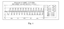
- Figures 3 and 4 illustrate an example of the result obtained with the limitation function LIC according to the invention.
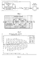
- FIG. 3 represents the no-load starting of an asynchronous motor under voltage and nominal frequencies without the LIC limitation function.
- the peak current in a phase reaches three times the nominal peak motor current (curve Is).
- the system according to the invention can be applied to a variator with or without a speed.
- the function performed by a microcontroller could be performed using electronic components.
Landscapes
- Engineering & Computer Science (AREA)
- Power Engineering (AREA)
- Control Of Ac Motors In General (AREA)
- Inverter Devices (AREA)
Applications Claiming Priority (2)
| Application Number | Priority Date | Filing Date | Title |
|---|---|---|---|
| FR0017344 | 2000-12-27 | ||
| FR0017344A FR2818826B1 (fr) | 2000-12-27 | 2000-12-27 | Systeme de limitation du courant en sortie d'un variateur de vitesse |
Publications (2)
| Publication Number | Publication Date |
|---|---|
| EP1229637A2 true EP1229637A2 (de) | 2002-08-07 |
| EP1229637A3 EP1229637A3 (de) | 2002-09-11 |
Family
ID=8858437
Family Applications (1)
| Application Number | Title | Priority Date | Filing Date |
|---|---|---|---|
| EP01205116A Withdrawn EP1229637A3 (de) | 2000-12-27 | 2001-12-21 | System zur Begrenzung des Ausgangsstromes eines Geschwindigkeitsreglers |
Country Status (4)
| Country | Link |
|---|---|
| US (1) | US6680599B2 (de) |
| EP (1) | EP1229637A3 (de) |
| JP (1) | JP2002238292A (de) |
| FR (1) | FR2818826B1 (de) |
Cited By (1)
| Publication number | Priority date | Publication date | Assignee | Title |
|---|---|---|---|---|
| FR2881296A1 (fr) * | 2005-01-27 | 2006-07-28 | Schneider Toshiba Inverter | Procede et systeme de limitation du courant en sortie d'un variateur de vitesse fonctionnant selon une loi de commande u/f |
Families Citing this family (1)
| Publication number | Priority date | Publication date | Assignee | Title |
|---|---|---|---|---|
| JP5893307B2 (ja) * | 2011-09-13 | 2016-03-23 | キヤノン株式会社 | 振動型アクチュエータの駆動装置 |
Family Cites Families (10)
| Publication number | Priority date | Publication date | Assignee | Title |
|---|---|---|---|---|
| US3824437A (en) * | 1969-08-14 | 1974-07-16 | Siemens Ag | Method for controlling asynchronous machines |
| DE2919852A1 (de) * | 1979-05-16 | 1980-12-04 | Siemens Ag | Lastzustandsregelung einer umrichtergespeisten asynchronmaschine |
| DE3026202A1 (de) * | 1980-07-10 | 1982-02-04 | Siemens AG, 1000 Berlin und 8000 München | Drehfeldmaschinenantrieb mit einer umrichtergespeisten drehfeldmaschine und einer mit zwei wechselspannungsintegratoren und einer rechenmodellschaltung verbundenen umrichtersteuerung |
| DE3212439C2 (de) * | 1982-04-02 | 1992-02-20 | Robert Prof.Dr.-Ing. 6100 Darmstadt Jötten | Verfahren zum Betrieb einer durch schnelle elektrische Stellglieder gespeisten Asynchronmaschine |
| US4461986A (en) * | 1983-04-20 | 1984-07-24 | Westinghouse Electric Corp. | Motor control apparatus with phase related detector |
| FI872593A7 (fi) * | 1986-08-18 | 1988-02-19 | Siemens Ag | Foerfarande och anordning foer att driva en faeltorienterad, med en styrbar omriktare matad vridfaeltmaskin. |
| FR2614481B1 (fr) * | 1987-02-13 | 1990-08-31 | Pk I | Procede de commande d'un moteur asynchrone et entrainement electrique mettant ce procede en application |
| US4904919A (en) * | 1988-06-21 | 1990-02-27 | Allen-Bradley Company, Inc. | Dual mode control of a PWM motor drive for current limiting |
| ATE131668T1 (de) * | 1991-04-11 | 1995-12-15 | Elin Energieanwendung | Verfahren und schaltungsanordnungen zur bestimmung maschinenbezogener elektromagnetischer und mechanischer zustandsgrössen an über umrichter gespeisten elektrodydynamischen drehfeldmaschinen |
| US5717305A (en) * | 1996-06-28 | 1998-02-10 | Seibel; Brian J. | Method and apparatus for starting an electric motor |
-
2000
- 2000-12-27 FR FR0017344A patent/FR2818826B1/fr not_active Expired - Fee Related
-
2001
- 2001-12-21 EP EP01205116A patent/EP1229637A3/de not_active Withdrawn
- 2001-12-27 US US10/026,550 patent/US6680599B2/en not_active Expired - Fee Related
- 2001-12-27 JP JP2001397432A patent/JP2002238292A/ja active Pending
Cited By (3)
| Publication number | Priority date | Publication date | Assignee | Title |
|---|---|---|---|---|
| FR2881296A1 (fr) * | 2005-01-27 | 2006-07-28 | Schneider Toshiba Inverter | Procede et systeme de limitation du courant en sortie d'un variateur de vitesse fonctionnant selon une loi de commande u/f |
| EP1686682A1 (de) * | 2005-01-27 | 2006-08-02 | Schneider Toshiba Inverter Europe SAS | Verfahren und System zur begrenzung des Ausgangsstroms für einen V/f Umrichter- |
| US7218074B2 (en) | 2005-01-27 | 2007-05-15 | Schneider Toshiba Inverter Europe Sas | Method and system for limiting the current output by a speed controller operating according to a U/F control law |
Also Published As
| Publication number | Publication date |
|---|---|
| US20020093308A1 (en) | 2002-07-18 |
| US6680599B2 (en) | 2004-01-20 |
| FR2818826A1 (fr) | 2002-06-28 |
| FR2818826B1 (fr) | 2003-02-07 |
| JP2002238292A (ja) | 2002-08-23 |
| EP1229637A3 (de) | 2002-09-11 |
Similar Documents
| Publication | Publication Date | Title |
|---|---|---|
| EP1788697B1 (de) | Gerät zur Korrektur des Leistungsfaktors für einen drehzahlgeregelten Antrieb | |
| FR2532490A1 (fr) | Dispositif de commande d'un moteur a courant continu sans balais | |
| FR2464520A1 (fr) | Systeme de commande de facteur de puissance pour moteur a induction a courant alternatif commande par onduleur | |
| FR2772154A1 (fr) | Circuit de commande pour la correction du facteur de puissance | |
| FR3070805A1 (fr) | Procede d'identification des parametres de saturation magnetique d'un moteur electrique asynchrone | |
| EP3229366A1 (de) | Steuerungsverfahren eines asynchronen elektromotors | |
| EP1229637A2 (de) | System zur Begrenzung des Ausgangsstromes eines Geschwindigkeitsreglers | |
| EP3528384B1 (de) | Steuerungsverfahren eines spannungswandlers, der mit einer elektrischen maschine verbunden ist | |
| FR2884079A1 (fr) | Commande d'un transistor mos | |
| EP2461467B1 (de) | Spannungswandler mit kontrollierter Stromquelle | |
| WO2007077372A2 (fr) | Procede de commande d'un onduleur de tension polyphase | |
| FR2702607A1 (fr) | Dispositif de commande du circuit oscillant d'un onduleur de tension fonctionnant en quasi-résonance à régulation à modulation de largeur d'impulsion. | |
| FR2896638A1 (fr) | Dispositif de pilotage d'une machine tournante polyphasee | |
| EP3462603B1 (de) | Steuerungsverfahren zur überprüfung der kompatibilität zwischen einem drehzahlregler und dem eingangsfilter | |
| EP1686682B1 (de) | Verfahren und System zur Begrenzung des Ausgangsstroms für einen V/f Umrichter | |
| EP2823562B1 (de) | Verfahren zur steuerung einer leistungsbrücke und zugehörige steuerungsvorrichtung, leistungsbrücke und elektrische drehmaschine | |
| WO2020099377A1 (fr) | Procede de commande pour convertisseur de puissance, systeme et dispositif associes | |
| FR2832872A1 (fr) | Unite de commande de moteur triphase sans balai avec possibilite de compensation dynamique du courant mesure | |
| FR2765746A1 (fr) | Procede et dispositif de commande de commutateurs pour regulation par modulation d'impulsions a frequence commandable | |
| FR2909816A1 (fr) | Appareil de commande de generateur de courant alternatif (ca) pour vehicule | |
| FR2684504A1 (fr) | Dispositif de controle de couple d'un moteur electrique asynchrone. | |
| WO2025056859A1 (fr) | Système de contrôle du courant de court-circuit d'un réseau électrique | |
| FR3090240A1 (fr) | Procédé de régulation d’un système de génération d’énergie électrique pour un réseau de distribution électrique d’un aéronef | |
| EP2458720A1 (de) | Spannungswandler mit einer gesteuerten Stromquelle und verbunden in Einzel-Phasen-Modus | |
| FR2587559A1 (fr) | Dispositif d'alimentation de machines a reluctance variable |
Legal Events
| Date | Code | Title | Description |
|---|---|---|---|
| PUAI | Public reference made under article 153(3) epc to a published international application that has entered the european phase |
Free format text: ORIGINAL CODE: 0009012 |
|
| PUAL | Search report despatched |
Free format text: ORIGINAL CODE: 0009013 |
|
| AK | Designated contracting states |
Kind code of ref document: A2 Designated state(s): AT BE CH CY DE DK ES FI FR GB GR IE IT LI LU MC NL PT SE TR |
|
| AX | Request for extension of the european patent |
Free format text: AL;LT;LV;MK;RO;SI |
|
| RAP1 | Party data changed (applicant data changed or rights of an application transferred) |
Owner name: SCHNEIDER ELECTRIC INDUSTRIES SAS |
|
| AK | Designated contracting states |
Kind code of ref document: A3 Designated state(s): AT BE CH CY DE DK ES FI FR GB GR IE IT LI LU MC NL PT SE TR |
|
| AX | Request for extension of the european patent |
Free format text: AL;LT;LV;MK;RO;SI |
|
| RIC1 | Information provided on ipc code assigned before grant |
Free format text: 7H 02P 1/26 A, 7H 02P 7/622 B |
|
| 17P | Request for examination filed |
Effective date: 20021001 |
|
| AKX | Designation fees paid |
Designated state(s): DE ES GB IT |
|
| GRAP | Despatch of communication of intention to grant a patent |
Free format text: ORIGINAL CODE: EPIDOSNIGR1 |
|
| RIC1 | Information provided on ipc code assigned before grant |
Ipc: H02P 1/26 20060101AFI20100201BHEP |
|
| STAA | Information on the status of an ep patent application or granted ep patent |
Free format text: STATUS: THE APPLICATION IS DEEMED TO BE WITHDRAWN |
|
| 18D | Application deemed to be withdrawn |
Effective date: 20100629 |