EP1229538A1 - Optical disk player and playback method - Google Patents
Optical disk player and playback method Download PDFInfo
- Publication number
- EP1229538A1 EP1229538A1 EP00970171A EP00970171A EP1229538A1 EP 1229538 A1 EP1229538 A1 EP 1229538A1 EP 00970171 A EP00970171 A EP 00970171A EP 00970171 A EP00970171 A EP 00970171A EP 1229538 A1 EP1229538 A1 EP 1229538A1
- Authority
- EP
- European Patent Office
- Prior art keywords
- amplitude
- positive
- mark
- optical disc
- signal
- Prior art date
- Legal status (The legal status is an assumption and is not a legal conclusion. Google has not performed a legal analysis and makes no representation as to the accuracy of the status listed.)
- Granted
Links
Images





Classifications
-
- G—PHYSICS
- G11—INFORMATION STORAGE
- G11B—INFORMATION STORAGE BASED ON RELATIVE MOVEMENT BETWEEN RECORD CARRIER AND TRANSDUCER
- G11B20/00—Signal processing not specific to the method of recording or reproducing; Circuits therefor
- G11B20/10—Digital recording or reproducing
- G11B20/10009—Improvement or modification of read or write signals
- G11B20/10046—Improvement or modification of read or write signals filtering or equalising, e.g. setting the tap weights of an FIR filter
- G11B20/10212—Improvement or modification of read or write signals filtering or equalising, e.g. setting the tap weights of an FIR filter compensation for data shift, e.g. pulse-crowding effects
-
- G—PHYSICS
- G11—INFORMATION STORAGE
- G11B—INFORMATION STORAGE BASED ON RELATIVE MOVEMENT BETWEEN RECORD CARRIER AND TRANSDUCER
- G11B20/00—Signal processing not specific to the method of recording or reproducing; Circuits therefor
- G11B20/10—Digital recording or reproducing
- G11B20/10009—Improvement or modification of read or write signals
-
- G—PHYSICS
- G11—INFORMATION STORAGE
- G11B—INFORMATION STORAGE BASED ON RELATIVE MOVEMENT BETWEEN RECORD CARRIER AND TRANSDUCER
- G11B20/00—Signal processing not specific to the method of recording or reproducing; Circuits therefor
- G11B20/10—Digital recording or reproducing
- G11B20/10009—Improvement or modification of read or write signals
- G11B20/10046—Improvement or modification of read or write signals filtering or equalising, e.g. setting the tap weights of an FIR filter
-
- G—PHYSICS
- G11—INFORMATION STORAGE
- G11B—INFORMATION STORAGE BASED ON RELATIVE MOVEMENT BETWEEN RECORD CARRIER AND TRANSDUCER
- G11B20/00—Signal processing not specific to the method of recording or reproducing; Circuits therefor
- G11B20/10—Digital recording or reproducing
- G11B20/10009—Improvement or modification of read or write signals
- G11B20/10305—Improvement or modification of read or write signals signal quality assessment
- G11B20/10314—Improvement or modification of read or write signals signal quality assessment amplitude of the recorded or reproduced signal
-
- G—PHYSICS
- G11—INFORMATION STORAGE
- G11B—INFORMATION STORAGE BASED ON RELATIVE MOVEMENT BETWEEN RECORD CARRIER AND TRANSDUCER
- G11B7/00—Recording or reproducing by optical means, e.g. recording using a thermal beam of optical radiation by modifying optical properties or the physical structure, reproducing using an optical beam at lower power by sensing optical properties; Record carriers therefor
- G11B7/12—Heads, e.g. forming of the optical beam spot or modulation of the optical beam
-
- G—PHYSICS
- G11—INFORMATION STORAGE
- G11B—INFORMATION STORAGE BASED ON RELATIVE MOVEMENT BETWEEN RECORD CARRIER AND TRANSDUCER
- G11B7/00—Recording or reproducing by optical means, e.g. recording using a thermal beam of optical radiation by modifying optical properties or the physical structure, reproducing using an optical beam at lower power by sensing optical properties; Record carriers therefor
- G11B7/12—Heads, e.g. forming of the optical beam spot or modulation of the optical beam
- G11B7/125—Optical beam sources therefor, e.g. laser control circuitry specially adapted for optical storage devices; Modulators, e.g. means for controlling the size or intensity of optical spots or optical traces
- G11B7/126—Circuits, methods or arrangements for laser control or stabilisation
- G11B7/1263—Power control during transducing, e.g. by monitoring
-
- G—PHYSICS
- G11—INFORMATION STORAGE
- G11B—INFORMATION STORAGE BASED ON RELATIVE MOVEMENT BETWEEN RECORD CARRIER AND TRANSDUCER
- G11B2220/00—Record carriers by type
- G11B2220/20—Disc-shaped record carriers
- G11B2220/25—Disc-shaped record carriers characterised in that the disc is based on a specific recording technology
- G11B2220/2537—Optical discs
-
- G—PHYSICS
- G11—INFORMATION STORAGE
- G11B—INFORMATION STORAGE BASED ON RELATIVE MOVEMENT BETWEEN RECORD CARRIER AND TRANSDUCER
- G11B7/00—Recording or reproducing by optical means, e.g. recording using a thermal beam of optical radiation by modifying optical properties or the physical structure, reproducing using an optical beam at lower power by sensing optical properties; Record carriers therefor
- G11B7/004—Recording, reproducing or erasing methods; Read, write or erase circuits therefor
- G11B7/005—Reproducing
Definitions
- the present invention relates to a playback apparatus and playback method for reading marks or spaces written to an optical disc.
- Writable optical discs are written with combinations of marks and spaces between marks.
- Mark length is 3T, 4T, 5T, 6T, 7T, 8T, 9T, 10T, or 11T
- space length is also 3T, 4T, 5T, 6T, 7T, 8T, 9T, 10T, or 11T.
- T denotes the period of the channel clock.
- the physical length of the shortest mark, 3T is approximately 0.4 ⁇ m
- the diameter (half width) of the light spot of the laser beam forming the marks is approximately 0.6 ⁇ m. Because of the distribution of the light intensity of the light spot, that is, because light spot intensity is greatest in the center and weakens to the periphery, momentary exposure to the light spot forms slightly smaller 0.4 ⁇ m marks instead of 0.6 ⁇ m marks.
- Fig. 6 shows an optical disc playback apparatus according to the prior art.
- Reference numeral 62 is an optical disc
- 64 is an optical head
- 66 is an amplifier
- 68 is an automatic gain controller
- 70 is a capacitance
- 72 is a resistance
- 74 is waveform equalizer for amplifying the frequency band of the reproduced signal
- 76 is a digitizer
- 78 is a phase-locked loop.
- a waveform equalizer 74 is conventionally inserted before the digitizer 76 in order to resolve the above-noted intersymbol interference.
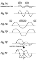
- the playback wave is amplified by the waveform equalizer 74. This operation is shown in Fig. 7.
- Fig. 7 (a) and (b) show a signal reproduced from short marks and the reproduced signal after amplification by the waveform equalizer 74.
- Fig. 7 (c) and (d) show a signal reproduced from long marks and the reproduced signal after amplification by the waveform equalizer 74.
- the line shown in the middle of each signal denotes the threshold value Vth of the digitizer 76.
- a 1 is output from the digitizer 76 when this threshold value Vth is exceeded, and a 0 is output when less than or equal to the threshold value Vth. Jitter in the playback signal is thus reduced by the waveform equalizer 74 amplifying the high frequency band of the playback signal.
- the point where the long mark playback signal intersects the threshold potential and the point where the short mark playback signal intersects the threshold potential can be matched as shown in Fig. 7 (e) by inputting the optical disc playback signal directly to the digitizer 76, but if the optical disc playback signal is input to the digitizer 76 through a waveform equalizer 74 with a high equalization coefficient K, the point where the long mark playback signal intersects the threshold potential will be shifted offset g as shown in Fig. 7 (f).
- This offset is a new source of jitter in the playback signal. This new jitter becomes increasingly pronounced as the recording density increases or the equalization coefficient K increases.
- An object of the present invention is to provide an optical disc playback apparatus capable of signal processing so that the above-noted new jitter does not appear even when a waveform equalizer is used.
- a playback apparatus for reading marks or spaces ("marks" below) written to an optical disc is characterized by comprising:
- a second aspect of the invention is a playback apparatus according to the first aspect wherein the trimmer means limits amplitude in the positive direction only.
- a third aspect of the invention is a playback apparatus according to the first aspect wherein the trimmer means limits amplitude in the positive direction and amplitude in the negative direction.
- a fourth aspect of the invention is a playback apparatus according to the third aspect wherein the amount cut by limiting amplitude in the positive direction is 55% or less of the maximum positive amplitude, and the amount cut by limiting amplitude in the negative direction is 50% or less of the maximum amplitude in the negative direction.
- a fifth aspect of the invention is a playback apparatus according to the third aspect wherein the trimmer means limits amplitude in the positive direction and amplitude in the negative direction in signals of an (n+2)T or longer mark length, and does not limit amplitude in the positive direction and amplitude in the negative direction in signals of an nT or (n+1)T mark length in modulation code where the shortest mark is nT (where n is a positive integer and T is the period of the channel clock).
- a sixth aspect of the invention is a playback apparatus according to the first aspect wherein the trimmer means limits amplitude when the ratio ML/Wh between pit length ML on the optical disc and half width Wh of the light spot satisfies the following relationship: ML/Wh ⁇ R 1.0 ⁇ R ⁇ 1.35.
- a seventh aspect of the invention is a playback apparatus according to the first aspect wherein the ratio between the shortest mark length MLmin of the optical disc and the half width Wh of the light spot satisfies the relationship MLmin/Wh ⁇ 0.82.
- An eighth aspect of the invention is a playback method for reading marks written to a writable optical disc, comprising:
- a ninth aspect of the invention is a playback method according to the eighth aspect wherein the step for substantially equalizing positive and negative amplitudes limits amplitude in the positive direction only.
- a tenth aspect of the invention is a playback method according to the eighth aspect wherein the step for substantially equalizing positive and negative amplitudes limits amplitude in the positive direction and amplitude in the negative direction.
- An eleventh aspect of the invention is an optical disc playback method according to the tenth aspect wherein the amount cut by limiting amplitude in the positive direction is 55% or less of the maximum positive amplitude, and the amount cut by limiting amplitude in the negative direction is 50% or less of the maximum amplitude in the negative direction.
- a twelfth aspect of the invention is an optical disc playback method according to the tenth aspect wherein the trimmer means limits amplitude in the positive direction and amplitude in the negative direction in signals of (n+2)T or longer mark length, and does not limit amplitude in the positive direction and amplitude in the negative direction in signals of nT or (n+1)T mark length when the shortest mark of the modulation code is nT (where n is a positive integer and T is the period of the channel clock).
- a thirteenth aspect of the invention is an optical disc playback method according to the eighth aspect wherein amplitude is limited by the step for substantially equalizing positive and negative amplitudes when the ratio ML/Wh between pit length ML on the optical disc and half width Wh of the light spot satisfies the following relationship: ML/Wh ⁇ R 1.0 ⁇ R ⁇ 1.35.
- a fourteenth aspect of the invention is an optical disc playback apparatus according to the eighth aspect wherein the ratio between the shortest mark length MLmin of the optical disc and the half width Wh of the light spot satisfies the relationship MLmin/Wh ⁇ 0.82.
- An optical disc playback apparatus and method capable of signal processing without producing jitter can be provided by means of the present invention.
- Fig. 1 shows a first embodiment of an optical disc playback apparatus according to the present invention.
- reference numeral 2 is an optical disc
- 4 is an optical head
- 6 is an amplifier
- 8 is an automatic gain controller
- 10 is a capacitance
- 11 is a resistance.
- Reference numeral 14 is a trimmer for limiting the maximum amplitude in the positive direction
- 16 is a waveform equalizer for amplifying the reproduced sinusoidal wave
- 18 is a digitizer
- 20 is a phase-locked loop.
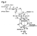
- the trimmer 14 comprises a resistance 14a, diode 14b, buffer 14c, and buffer 14d; signal X1 specifying the upper limit is input to the input of buffer 14c.
- the waveform equalizer 16 comprises delay circuits 16a and 16b, amplifiers 16c and 16d, and adder 16e.
- a writable optical disc 2 is recorded using combinations of phase-change marks and spaces between marks.
- Mark length is 3T, 4T, 5T, 6T, 7T, 8T, 9T, 10T, or 11T
- space length is also 3T, 4T, 5T, 6T, 7T, 8T, 9T, 10T, or 11T.
- T denotes the period of the channel clock.
- the shortest mark or space in this case is 3T, having a physical length of approximately 0.2 ⁇ m to 0.4 ⁇ m; the diameter (half width) of the light spot of the laser beam for reproducing marks is approximately 0.4 ⁇ m to 0.6 ⁇ m.
- the longest mark or space in this case is 11T, having a physical length of approximately 0.7 ⁇ m to 1.5 ⁇ m
- a playback signal of the marks and spaces (collectively referred to below as "marks") read by the optical head 4 is amplified by amplifier 6 and automatic gain controller 8, unnecessary frequency components are cut by capacitances 10 and 12, and the signal is input to the trimmer 14.
- the signal input to the trimmer 14 is S1
- the signal output form the trimmer 14 is S2
- the signal output from the waveform equalizer 16 is S3.
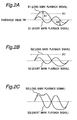
- Fig. 2 (a) shows a playback signal S1 for a long mark and a playback signal S1 for a short mark. That A1 > A2 when amplitude A1 in the positive direction from the threshold value Vth and amplitude A2 in the negative direction are compared was observed from experiments as a feature of this playback signal S1. In other words, amplitude in the positive direction and amplitude in the negative direction with respect to threshold value Vth are asymmetrical.
- the trimmer 14 is a circuit for eliminating or reducing this asymmetry. That is, when amplitude A1 in the positive direction exceeds the level of X1, the trimmer 14 cuts off the signal at the level of X1 and thus limits the maximum amplitude A1 in the positive direction to the level of X1. Playback signal S2 is shown in Fig. 2 (b). Long mark playback signal S2 is cut off at level X1, but short mark playback signal S2 is less than or equal to level X1 and is therefore not cut off.
- Playback signal S2 is input to the waveform equalizer 16 and amplified.
- the amplified signal S3 is shown in Fig. 2 (c).
- the waveform equalizer 16 works to increase the slope of the wave. Overshoot therefore appears at the edge cut off at level X1.
- playback signal S2 cutoff at level X1 and particularly long mark playback signal S2
- the waveform equalizer 16 the offset at the intersection of the playback signal 2 with threshold value Vth is greatly reduced. Producing new jitter in the playback signal as a result of this offset is thus avoided. As a result, playback signal jitter can be improved.
- Fig. 3 shows a second embodiment of an optical disc playback apparatus according to the present invention.
- the optical disc playback apparatus shown in Fig. 3 differs in the configuration of the trimmer 114, and because the configuration of other parts is the same as the configuration of the optical disc playback apparatus shown in Fig. 1 only the configuration of the trimmer 114 is described below and description regarding the configuration of other parts is omitted.
- the trimmer 114 comprises a resistance 14a, diodes 14b and 14e, buffers 14c and 14f, and buffer 14d; signal X1 specifying the upper limit is input to the input of buffer 14c and signal X2 specifying the lower limit is input to the input of buffer 14f.
- the signal input to the trimmer 114 is S1
- the signal output form the trimmer 114 is S2
- the signal output from the waveform equalizer 16 is S3.
- Fig. 4 (a) shows a playback signal S1 for a long mark and a playback signal S1 for a short mark. That when amplitude A1 in the positive direction from the threshold value Vth and amplitude A2 in the negative direction are compared A1 > A2 and are asymmetrical is the same as noted above.
- the trimmer 114 is a circuit for eliminating or reducing this asymmetry. That is, when amplitude A1 in the positive direction exceeds the level of X1, the trimmer 114 cuts off the signal at the level of X1 and thus limits the maximum amplitude A1 in the positive direction to the level of X1, and when amplitude A2 in the negative direction exceeds the level of X2, the trimmer 114 cuts off the signal at the level of X2 and thus limits the minimum negative amplitude A2.
- Playback signal S2 is shown in Fig. 3 (b). Long mark playback signal S2 is cut off in the positive direction at level X1 and is cut off in the negative direction at level X2. The short mark playback signal S2 is between levels X1 and X2 and is therefore not cut.
- Playback signal S2 is input to the waveform equalizer 16 and amplified.
- the amplified signal S3 is shown in Fig. 3 (c).
- the waveform equalizer 16 works to increase the slope of the wave. Overshoot therefore appears at the edges cut off at levels X1 and X2.
- playback signal S2 cutoff at level X1 or X2, and particularly long mark playback signal S2 is amplified by the waveform equalizer 16
- the offset at the intersection of the playback signal 2 with threshold value Vth is greatly reduced. Producing new jitter in the playback signal as a result of this offset is thus avoided.
- playback signal jitter can be improved.
- Jitter G (%) is obtained with the following equation.
- G g 1 2 + g 2 2 + ... + gm 2 mT ⁇ 100 (%) where g1 to gm denote the offset (offset g shown in Fig. 7 (f)) appearing in a specific interval in order.
- jitter is 12.3%.
- A1 ⁇ 1.1A2 as shown in Fig. 5 (a).
- jitter is 10.6%.
- jitter is 7.3%.
- a jitter level of 6.9% was obtained as a result of finding the lowest jitter level achieved with the second embodiment shown in Fig. 3.
- the signal amplitude of the playback signal S2 input to the waveform equalizer 16 in this case was cut off in both positive and negative directions, and A1 ⁇ 1.1A2. This was also achieved by trimming to approximately 5% to 55% in the positive direction and 1% to 50% in the negative direction.
- Cut-off levels X1 and X2 desirably do not cut the signal amplitude to the amplitude of a signal for a short mark such as a 3T mark. Cut-off levels X1 and X2 are preferably set so that (X1 - Xth) ⁇ (Vth - X2), that is, so that the positive amplitude and negative amplitude are substantially the same, but it is even further preferable for the positive amplitude (X1 - Xth) to be 0.2% to several percent greater than the negative amplitude (Vth - X2).
- the light spot can be thought of as a Gaussian distribution. Movement of the light spot along the track over the marks and spaces can be thought of as a Gaussian distribution moving along the track over the marks and spaces.
- the area of the Gaussian distribution is 1 in this example.
- the playback signal level when a mark is not in the Gaussian distribution is -1.
- the playback signal level when a mark covers half the Gaussian distribution, that is, when the leading edge of the mark is positioned at the middle of the Gaussian distribution, the playback signal level is 0.
- the playback signal level when the mark completely fills the Gaussian distribution the playback signal level is +1.
- the playback signal level changes from -1 to 0 and then to +1 as indicated by line 900 in Fig. 9.
- the playback signal level goes to 0 precisely when the leading edge of the mark is positioned at the center of the Gaussian distribution.
- the playback signal level is -1 when no part of the mark is within the Gaussian distribution.
- the playback signal level is a slightly negative value (- ⁇ S) rather than 0 when the leading edge of the mark is positioned at the center of the Gaussian distribution.
- the playback signal level peaks but the peak value is slightly less than +1. It should be noted that Figs. 8, 9, and 10 show a case using 8-16 modulation as the modulation code.
- the playback signal level when the leading edge of the mark is positioned at the center of the Gaussian distribution (referred to below as the edge-center point) can be expressed using intersymbol interference - ⁇ S.
- of the playback signal level (- ⁇ S) at the edge-center point increases as the mark length ML becomes shorter than the width GW of the Gaussian distribution. That the playback signal level at this edge-center point moves from 0 in the negative direction is also considered a factor contributing to offset g.
- the magnitude of level X1 in the present invention is therefore set so that cut off at level X1 starts at the point where the playback signal level at the edge-center point substantially rises from a negative value to substantially 0, such as when it approaches to within -0.01 of 0, as the mark length ML is sequentially increased from the shortest mark length.
- the playback signal level at the edge-center point of the waveform 901 for a 3T mark is -0.099, -0.028 for waveform 902 for a 4T mark, and -0.006 for waveform 903 for a 5T mark.
- Level X1 is therefore set between the peak of the 4T mark wave and the peak of the 5T mark wave.
- level X1 is set so that the signal is trimmed when ML/Wh ⁇ R 1.0 ⁇ R ⁇ 1.35.
- reference numeral 803 is the half width Wh of the light spot, indicating the width of the distribution where power is 1/2 the peak power of the light spot distribution, and is approximately 0.6 ⁇ m in a DVD.
- the playback signal level is -1 (minimum signal level) at a sufficiently long space, and the playback signal level is +1 (maximum signal level) at a sufficiently long mark
- Gaussian distribution Sf(x) denoting the light spot can be expressed with equation 1 (x is the distance from the light spot center).
- the playback signal level at a certain time can be determined by subtracting the integral of all parts where the mark is not present from the integral of all parts where the mark is present as shown in equation 1.
- the integral of applying equation 1 to the entire area is 1.
- Intersymbol interference is described here using 8-16 modulation as the modulation code. For simplicity, intersymbol interference resulting from successive marks is described below assuming a signal in which a 3T mark, 4T mark, 5T mark, and 6T mark follow a sufficiently long space.
- the playback wave for the above is shown in Fig. 9.
- reference numeral 901 is a 3T mark
- 902 is a 4T mark
- 903 is a 5T mark
- 904 is a 6T mark.
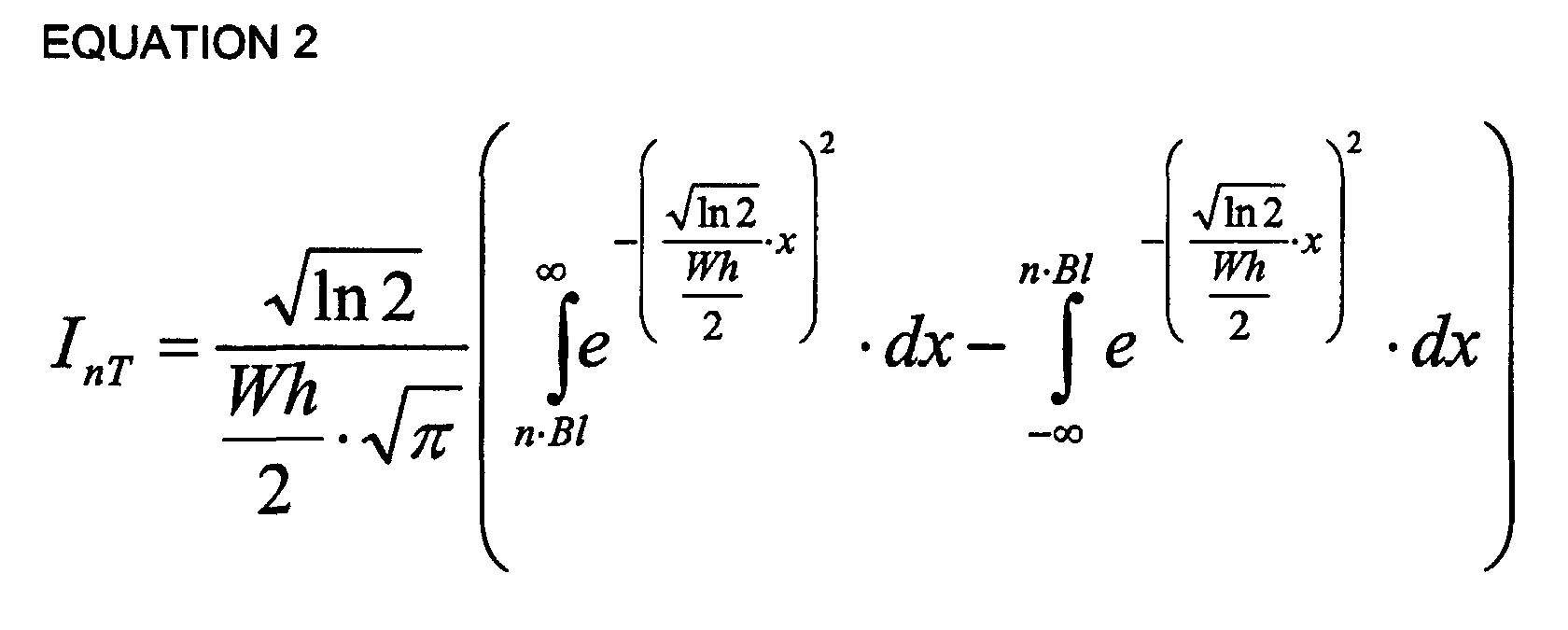
- Equation 2 The playback signal level when the light spot is located at the change between a sufficiently long space and an nT mark is shown by equation 2 in which equation 1 is integrated from 0 to (n x B1).
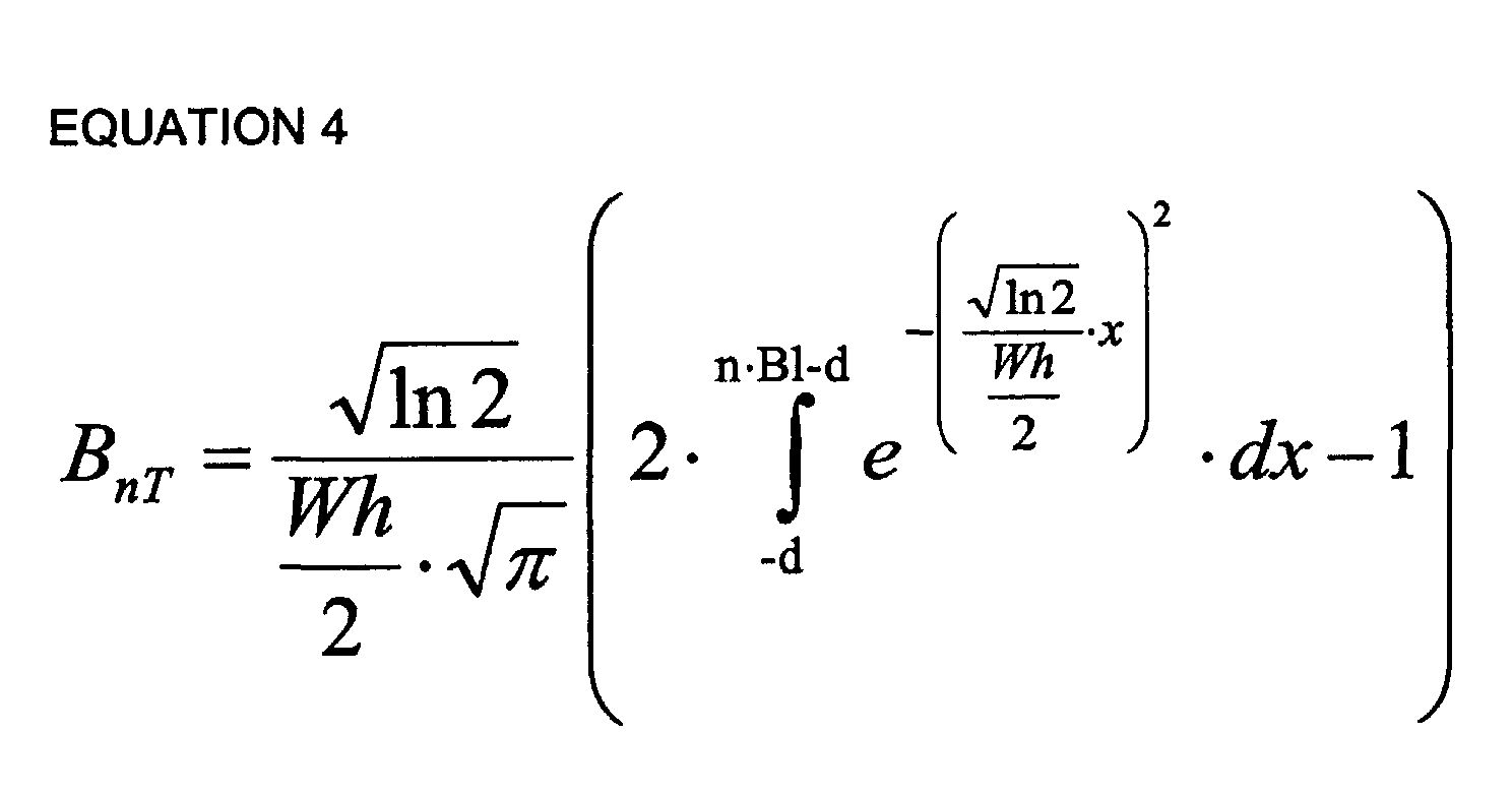
- the present invention is particularly effective with high density recording where InT and (AnT+BnT) deviate from a proportional relationship in the waveform when amplitude limiting (trimming at level X1) is not applied.
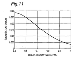
- the relationship between linear density and 4T mark error with a conventional waveform equalization circuit in which amplitude limiting is not applied is shown in Fig. 11.
- linear density is defined as the ratio between the shortest mark length MLmin and the half width Wh of the light spot
- the present invention is effective when the error in Fig. 11 is 0.010 or greater. With respect to linear density, the present invention is effective when the ratio of the shortest mark length and light spot half width is 0.82 or less. The invention is even more effective when the error is 0.018 or greater and linear density is 0.70 or less.
- intersymbol interference resulting from a mark following a space is described by way of example above, but the same applies when the space and mark are reversed as the sign simply inverts. Furthermore, the same also applies to intersymbol interference resulting from a mark before a space because this is equivalent to inverting the time base and AnT and BnT are simply reversed. In effect, the same applies to all combinations.
- modulation code in which 2T is the shortest mark such as in (1,7) modulation
- 2T in (1,7) modulation substitutes for 3T in the above-described 8-16 modulation
- 3T in (1,7) modulation substitutes for 4T in 8-16 modulation.
- offset g can be reduced and playback signal jitter can be improved by trimming peaks to at least one side, such as by cutting the amplitude in the positive direction, of the playback signal, and preferably playback signal S2 input to the waveform equalizer, before it is input to the digitizer 18.
Landscapes
- Engineering & Computer Science (AREA)
- Signal Processing (AREA)
- Physics & Mathematics (AREA)
- Optics & Photonics (AREA)
- Optical Recording Or Reproduction (AREA)
- Signal Processing For Digital Recording And Reproducing (AREA)
Abstract
Description


Claims (14)
- A playback apparatus for reading marks or spaces (marks, below) written to an optical disc, comprising:an optical head means for emitting a light spot to a mark, reading the mark, and outputting a playback signal;a trimmer means for limiting at least the greater of positive amplitude or negative amplitude in the playback signal output from the optical head relative to a specified threshold value for converting to a binary signal so that both positive and negative amplitudes are substantially equal;a waveform equalization circuit for amplifying the high frequency band of the output signal from the trimmer means; anda digitizing circuit for converting the output signal from the waveform equalization circuit to a binary signal using the specified threshold value.
- A playback apparatus as described in claim 1, wherein the trimmer means limits amplitude in the positive direction only.
- A playback apparatus as described in claim 1, wherein the trimmer means limits amplitude in the positive direction and amplitude in the negative direction.
- An optical disc playback apparatus as described in claim 3, wherein the amount cut by limiting amplitude in the positive direction is 55% or less of the maximum positive amplitude, and the amount cut by limiting amplitude in the negative direction is 50% or less of the maximum amplitude in the negative direction.
- An optical disc playback apparatus as described in claim 3, wherein the trimmer means limits amplitude in the positive direction and amplitude in the negative direction in signals of an (n+2)T or longer mark length, and does not limit amplitude in the positive direction and amplitude in the negative direction in signals of an nT or (n+1)T mark length in modulation code where the shortest mark is nT (where n is a positive integer and T is the period of the channel clock).
- An optical disc playback apparatus as described in claim 1, wherein the trimmer means limits amplitude when the ratio ML/Wh between pit length ML on the optical disc and half width Wh of the light spot satisfies the following relationship:
- An optical disc playback apparatus as described in claim 1, wherein the ratio between the shortest mark length MLmin of the optical disc and the half width Wh of the light spot satisfies the relationship
- A playback method for reading marks written to a writable optical disc, comprising:a step for emitting a light spot from an optical head to a mark, reading the mark, and outputting a playback signal;a step for limiting at least the greater of positive amplitude or negative amplitude in the playback signal output from the optical head relative to a specified threshold value for converting to a binary signal so that both positive and negative amplitudes are substantially equal;a step for amplifying the signal of substantially equal positive and negative amplitudes; anda step for converting the amplified signal to a binary signal using the specified threshold value.
- A playback method as described in claim 8, wherein the step for substantially equalizing positive and negative amplitudes limits amplitude in the positive direction only.
- A playback method as described in claim 8, wherein the step for substantially equalizing positive and negative amplitudes limits amplitude in the positive direction and amplitude in the negative direction.
- An optical disc playback method as described in claim 10, wherein the amount cut by limiting amplitude in the positive direction is 55% or less of the maximum positive amplitude, and the amount cut by limiting amplitude in the negative direction is 50% or less of the maximum amplitude in the negative direction.
- An optical disc playback method as described in claim 10, wherein the trimmer means limits amplitude in the positive direction and amplitude in the negative direction in signals of (n+2)T or longer mark length, and does not limit amplitude in the positive direction and amplitude in the negative direction in signals of nT or (n+1)T mark length when the shortest mark of the modulation code is nT (where n is a positive integer and T is the period of the channel clock).
- An optical disc playback method as described in claim 8, wherein amplitude is limited by the step for substantially equalizing positive and negative amplitudes when the ratio ML/Wh between pit length ML on the optical disc and half width Wh of the light spot satisfies the following relationship:
- An optical disc playback apparatus as described in claim 8, wherein the ratio between the shortest mark length MLmin of the optical disc and the half width Wh of the light spot satisfies the relationship
Applications Claiming Priority (3)
| Application Number | Priority Date | Filing Date | Title |
|---|---|---|---|
| JP30886799 | 1999-10-29 | ||
| JP30886799 | 1999-10-29 | ||
| PCT/JP2000/007588 WO2001033568A1 (en) | 1999-10-29 | 2000-10-27 | Optical disk player and playback method |
Publications (3)
| Publication Number | Publication Date |
|---|---|
| EP1229538A1 true EP1229538A1 (en) | 2002-08-07 |
| EP1229538A4 EP1229538A4 (en) | 2002-12-04 |
| EP1229538B1 EP1229538B1 (en) | 2003-09-03 |
Family
ID=17986224
Family Applications (1)
| Application Number | Title | Priority Date | Filing Date |
|---|---|---|---|
| EP00970171A Expired - Lifetime EP1229538B1 (en) | 1999-10-29 | 2000-10-27 | Optical disk player and playback method |
Country Status (6)
| Country | Link |
|---|---|
| US (1) | US6665250B1 (en) |
| EP (1) | EP1229538B1 (en) |
| KR (1) | KR100530167B1 (en) |
| CN (1) | CN1190789C (en) |
| DE (1) | DE60005044T2 (en) |
| WO (1) | WO2001033568A1 (en) |
Cited By (3)
| Publication number | Priority date | Publication date | Assignee | Title |
|---|---|---|---|---|
| EP1098312A3 (en) * | 1999-11-04 | 2004-04-21 | Pioneer Corporation | Waveform equalizer |
| EP1426956A3 (en) * | 2002-12-02 | 2004-06-30 | Samsung Electronics Co., Ltd. | Equalizer for high density optical disc reproducing apparatus and equalizing method therefor |
| US7580334B2 (en) | 2002-04-03 | 2009-08-25 | Panasonic Corporation | Optical storage medium inspection apparatus for determining whether an optical storage medium is good or defective |
Families Citing this family (8)
| Publication number | Priority date | Publication date | Assignee | Title |
|---|---|---|---|---|
| US6922384B2 (en) | 2000-11-30 | 2005-07-26 | Matsushita Electric Industrial Co., Ltd. | Information reproducing apparatus |
| WO2003005356A2 (en) * | 2001-07-02 | 2003-01-16 | Koninklijke Philips Electronics N.V. | Waveform equalizer for obtaining a corrected signal and apparatus for reproducing information |
| KR101044767B1 (en) * | 2003-05-27 | 2011-06-29 | 톰슨 라이센싱 | RF signal digital partial response asymmetry compensation |
| JP4453567B2 (en) * | 2005-02-09 | 2010-04-21 | ソニー株式会社 | Recording apparatus, recording method, and disc manufacturing method |
| JP4978940B2 (en) * | 2006-10-31 | 2012-07-18 | パイオニア株式会社 | Information recording apparatus and method, and computer program |
| WO2008053543A1 (en) * | 2006-10-31 | 2008-05-08 | Pioneer Corporation | Device and method for reproducing information and computer program |
| WO2009079789A1 (en) | 2007-12-21 | 2009-07-02 | Leddartech Inc. | Detection and ranging methods and systems |
| BE1020311A3 (en) | 2012-02-28 | 2013-07-02 | Atlas Copco Airpower Nv | SCREW COMPRESSOR. |
Family Cites Families (7)
| Publication number | Priority date | Publication date | Assignee | Title |
|---|---|---|---|---|
| JP2754920B2 (en) | 1990-12-27 | 1998-05-20 | 日本電気株式会社 | Recorded information playback device |
| JPH08106724A (en) | 1994-10-05 | 1996-04-23 | Olympus Optical Co Ltd | Information reproducing apparatus |
| JP3046515B2 (en) * | 1994-12-16 | 2000-05-29 | シャープ株式会社 | Reproducing circuit of optical information recording / reproducing device |
| JP2703198B2 (en) | 1995-03-24 | 1998-01-26 | 富士通テン株式会社 | Optical disc player |
| JP3042458B2 (en) | 1997-08-25 | 2000-05-15 | 日本電気株式会社 | Information recording / reproducing apparatus and information recording / reproducing method |
| JP3459563B2 (en) | 1998-03-06 | 2003-10-20 | パイオニア株式会社 | Waveform equalizer and recorded information reproducing device |
| JP3824437B2 (en) | 1998-12-15 | 2006-09-20 | パイオニア株式会社 | Waveform equalization circuit and data reproduction device |
-
2000
- 2000-10-27 KR KR10-2002-7005139A patent/KR100530167B1/en not_active Expired - Fee Related
- 2000-10-27 WO PCT/JP2000/007588 patent/WO2001033568A1/en not_active Ceased
- 2000-10-27 CN CNB008149615A patent/CN1190789C/en not_active Expired - Fee Related
- 2000-10-27 DE DE60005044T patent/DE60005044T2/en not_active Expired - Fee Related
- 2000-10-27 EP EP00970171A patent/EP1229538B1/en not_active Expired - Lifetime
- 2000-10-27 US US10/111,330 patent/US6665250B1/en not_active Expired - Fee Related
Cited By (9)
| Publication number | Priority date | Publication date | Assignee | Title |
|---|---|---|---|---|
| EP1098312A3 (en) * | 1999-11-04 | 2004-04-21 | Pioneer Corporation | Waveform equalizer |
| US6816547B1 (en) | 1999-11-04 | 2004-11-09 | Pioneer Corporation | Waveform equalizer |
| US7269214B2 (en) | 1999-11-04 | 2007-09-11 | Pioneer Corporation | Waveform equalizer |
| US7580334B2 (en) | 2002-04-03 | 2009-08-25 | Panasonic Corporation | Optical storage medium inspection apparatus for determining whether an optical storage medium is good or defective |
| US7583578B2 (en) | 2002-04-03 | 2009-09-01 | Panasonic Corporation | Optical storage medium inspection method for determining if an optical storage medium is good or defective |
| US7869326B2 (en) | 2002-04-03 | 2011-01-11 | Panasonic Corporation | Optical disc drive, optical storage medium, optical storage medium inspection apparatus, and optical storage medium inspection method |
| USRE44808E1 (en) | 2002-04-03 | 2014-03-18 | Panasonic Corporation | Optical disc drive, optical storage medium, optical storage medium inspection apparatus, and optical storage medium inspection method |
| EP1426956A3 (en) * | 2002-12-02 | 2004-06-30 | Samsung Electronics Co., Ltd. | Equalizer for high density optical disc reproducing apparatus and equalizing method therefor |
| US7330408B2 (en) | 2002-12-02 | 2008-02-12 | Samsung Electronics Co., Ltd. | Equalizer for high density optical disc reproducing apparatus and equalizing method therefor |
Also Published As
| Publication number | Publication date |
|---|---|
| WO2001033568A1 (en) | 2001-05-10 |
| CN1190789C (en) | 2005-02-23 |
| CN1384965A (en) | 2002-12-11 |
| EP1229538B1 (en) | 2003-09-03 |
| EP1229538A4 (en) | 2002-12-04 |
| DE60005044T2 (en) | 2004-06-03 |
| KR20020040906A (en) | 2002-05-30 |
| US6665250B1 (en) | 2003-12-16 |
| DE60005044D1 (en) | 2003-10-09 |
| KR100530167B1 (en) | 2005-11-22 |
Similar Documents
| Publication | Publication Date | Title |
|---|---|---|
| EP1229538B1 (en) | Optical disk player and playback method | |
| EP0268454B1 (en) | Optical disk recording and reproducing device | |
| KR100357641B1 (en) | Offset control circuit and offset control method | |
| US7068573B2 (en) | Reproducing device and method of removing noise | |
| US7529173B2 (en) | Optical disc device, circuit for optical disc device, wobble signal reproduction method, and land pre-pit signal reproduction method | |
| US6243354B1 (en) | Optical disk having high recording density | |
| JP4579803B2 (en) | Optical disk device | |
| JP2009289314A (en) | Optical disc device and optical disc playback method | |
| US20110013499A1 (en) | Recording apparatus and method, and computer program | |
| KR100284787B1 (en) | Data slice circuit and data slice method | |
| JPWO2001033568A1 (en) | Optical disc playback device and playback method | |
| KR100272542B1 (en) | Bit data reproduction method of digital disc | |
| JP2812035B2 (en) | Waveform shaping circuit | |
| US20090135692A1 (en) | Apparatus and method for determining write strategy, and apparatus and method for recording data | |
| JPH10222847A (en) | Information recording medium, information recording device and information reproducing device | |
| JP2861627B2 (en) | Recorded information playback device | |
| JPH08287478A (en) | Focus control device | |
| US20070030780A1 (en) | System and method of estimating the tangential tilt of an optical data carrier... | |
| CN100423096C (en) | Optical information recording device and laser control circuit | |
| EP1879190A1 (en) | Optical disc playback apparatus and method to improve the playability of an optical disc | |
| JP2007242106A (en) | RF signal shaping circuit | |
| JP2001052341A (en) | Data playback device for optical disc playback device | |
| JPS6235710A (en) | Signal level determination device | |
| JPH01292671A (en) | Binarization circuit for optical recording medium reproducing device | |
| JPH0573911A (en) | Optical memory device |
Legal Events
| Date | Code | Title | Description |
|---|---|---|---|
| PUAI | Public reference made under article 153(3) epc to a published international application that has entered the european phase |
Free format text: ORIGINAL CODE: 0009012 |
|
| 17P | Request for examination filed |
Effective date: 20020529 |
|
| AK | Designated contracting states |
Kind code of ref document: A1 Designated state(s): AT BE CH CY DE DK ES FI FR GB GR IE IT LI LU MC NL PT SE |
|
| AX | Request for extension of the european patent |
Free format text: AL;LT;LV;MK;RO;SI |
|
| A4 | Supplementary search report drawn up and despatched |
Effective date: 20021022 |
|
| AK | Designated contracting states |
Kind code of ref document: A4 Designated state(s): AT BE CH CY DE DK ES FI FR GB GR IE IT LI LU MC NL PT SE |
|
| RIC1 | Information provided on ipc code assigned before grant |
Free format text: 7G 11B 20/10 A |
|
| GRAH | Despatch of communication of intention to grant a patent |
Free format text: ORIGINAL CODE: EPIDOS IGRA |
|
| GRAS | Grant fee paid |
Free format text: ORIGINAL CODE: EPIDOSNIGR3 |
|
| GRAA | (expected) grant |
Free format text: ORIGINAL CODE: 0009210 |
|
| AK | Designated contracting states |
Kind code of ref document: B1 Designated state(s): DE FR GB |
|
| REG | Reference to a national code |
Ref country code: GB Ref legal event code: FG4D |
|
| REF | Corresponds to: |
Ref document number: 60005044 Country of ref document: DE Date of ref document: 20031009 Kind code of ref document: P |
|
| REG | Reference to a national code |
Ref country code: IE Ref legal event code: FG4D |
|
| LTIE | Lt: invalidation of european patent or patent extension |
Effective date: 20030903 |
|
| ET | Fr: translation filed | ||
| PLBE | No opposition filed within time limit |
Free format text: ORIGINAL CODE: 0009261 |
|
| STAA | Information on the status of an ep patent application or granted ep patent |
Free format text: STATUS: NO OPPOSITION FILED WITHIN TIME LIMIT |
|
| REG | Reference to a national code |
Ref country code: IE Ref legal event code: MM4A |
|
| 26N | No opposition filed |
Effective date: 20040604 |
|
| PGFP | Annual fee paid to national office [announced via postgrant information from national office to epo] |
Ref country code: DE Payment date: 20061019 Year of fee payment: 7 |
|
| PGFP | Annual fee paid to national office [announced via postgrant information from national office to epo] |
Ref country code: GB Payment date: 20061025 Year of fee payment: 7 |
|
| GBPC | Gb: european patent ceased through non-payment of renewal fee |
Effective date: 20071027 |
|
| PG25 | Lapsed in a contracting state [announced via postgrant information from national office to epo] |
Ref country code: DE Free format text: LAPSE BECAUSE OF NON-PAYMENT OF DUE FEES Effective date: 20080501 |
|
| REG | Reference to a national code |
Ref country code: FR Ref legal event code: ST Effective date: 20080630 |
|
| PGFP | Annual fee paid to national office [announced via postgrant information from national office to epo] |
Ref country code: FR Payment date: 20061010 Year of fee payment: 7 |
|
| PG25 | Lapsed in a contracting state [announced via postgrant information from national office to epo] |
Ref country code: GB Free format text: LAPSE BECAUSE OF NON-PAYMENT OF DUE FEES Effective date: 20071027 |
|
| PG25 | Lapsed in a contracting state [announced via postgrant information from national office to epo] |
Ref country code: FR Free format text: LAPSE BECAUSE OF NON-PAYMENT OF DUE FEES Effective date: 20071031 |