EP1229306A1 - Movable body progress direction navigating apparatus - Google Patents
Movable body progress direction navigating apparatus Download PDFInfo
- Publication number
- EP1229306A1 EP1229306A1 EP02002480A EP02002480A EP1229306A1 EP 1229306 A1 EP1229306 A1 EP 1229306A1 EP 02002480 A EP02002480 A EP 02002480A EP 02002480 A EP02002480 A EP 02002480A EP 1229306 A1 EP1229306 A1 EP 1229306A1
- Authority
- EP
- European Patent Office
- Prior art keywords
- movable body
- point
- directional data
- data
- approach
- Prior art date
- Legal status (The legal status is an assumption and is not a legal conclusion. Google has not performed a legal analysis and makes no representation as to the accuracy of the status listed.)
- Granted
Links
Images


Classifications
-
- G—PHYSICS
- G01—MEASURING; TESTING
- G01C—MEASURING DISTANCES, LEVELS OR BEARINGS; SURVEYING; NAVIGATION; GYROSCOPIC INSTRUMENTS; PHOTOGRAMMETRY OR VIDEOGRAMMETRY
- G01C21/00—Navigation; Navigational instruments not provided for in groups G01C1/00 - G01C19/00
- G01C21/26—Navigation; Navigational instruments not provided for in groups G01C1/00 - G01C19/00 specially adapted for navigation in a road network
- G01C21/34—Route searching; Route guidance
Definitions
- the present invention relates to a movable body progress direction navigating apparatus for navigating a movable body such as a vehicle or a walking human being for example into a predetermined progress direction and, more particularly, to a movable body progress direction navigating apparatus which, while being easily portable and small in size to facilitate the carriage especially on two-wheeled vehicles and pedestrians, correctly navigate them from a via-point into a predetermined direction.
- Navigation systems for displaying a optimum route from a start point to a destination by registering them beforehand are in wide use.
- a navigation system (a first related art technology) having a back-track mode known as product name "Magellan GPS 3000 Satellite Navigator” is sold (from December 1995 in Japan) from Mazellan Systems Japan Corporation, in which, halfway between a start point and destination, via-points are sequentially registered as "waypoints" and, in a return way, the registered waypoints are reversely followed to correctly reach the start point in the same route as the outward route.
- this back-track mode the distance and direction from each waypoint to another are displayed in each return route.
- the current positions can be registered as via-point data (waypoints) during traveling; however, the approach direction to each waypoint and the departing direction therefrom cannot be registered. Consequently, as shown in FIG. 9, the progress direction represented by waypoint WP2 by the back track mode in return route becomes the direction of next (one point before in approach route) waypoint WP1 as shown in a dashed-line circle.
- the progress direction from each via-point inputted for approach route cannot be used for return route. Therefore, like the above-mentioned first related art technology, if the road status is as shown in FIG. 9, the movable body may be navigated along a wrong road.
- a movable body progress direction navigating apparatus for navigating a movable body in a predetermined direction, including track detecting means for continuously detecting positional data of a movable body to obtain a track thereof; directional data generating means for generating, on the basis of the locus of the movable body, at least one of approach directional data obtained when the movable body has entered into a predetermined via-point and departing directional data obtained when the movable body has departed from the via-point; directional data storing means for storing at least one of the approach direction data and the departing directional data in association with positional data of the via-point; and when the movable body has approached the via-point, navigating means for navigating the movable body in a predetermined progress direction, on the basis of at least one of the approach directional data or the departing directional data, whichever is stored in the directional data storing means.
- the approach directional data and departing direction data of a movable body are stored in memory for each via-point, so that, when the movable body subsequently passes each via point again, the movable body can be correctly navigated in the normal direction from each via-point on the basis of the stored approach directional data and departing directional data.
- FIG. 1 there is shown a front view of an exemplary display panel of a movable body incorporating a progress direction navigating system according to the invention.
- the movable body is embodied in a vehicle.
- a display panel 6 has a direction display section 6a for indicating the direction of a destination where the progress direction (N) of the vehicle is above, a speed meter 6b, a remaining distance bar graph 6c for indicating a distance to the destination to be traveled in a bar graph, a remaining distance meter 6d for indicating a distance to be traveled in a numeric value, a remaining distance set button 6e, a distance meter 6f for indicating a total travel distance of the vehicle, and a time meter 6g for indicating a total travel time.
- the direction display section 6a can show 8 directions with intervals of 45 degrees.
- the remaining distance bar graph 6c has a reference distance marker 10 and 5 equidistant scales 11 for example.
- the remaining distance bar graph 6c is colored (in blue for example) full scale to the right from the reference distance marker 10 and a straight line from the current position to the destination is shown in a numeric value. For example, if a total distance from the current position to the destination is 500 km, the bar graph is displayed full scale as shown in FIG. 2(a) and a remaining distance of 50 km is displayed in numeric value on the remaining distance meter 6d.
- the remaining distance bar graph 6c turns off up to the third scale from the reference distance marker 10, turning off the section to the right of the third scale.
- the remaining distance meter 6d shows a remaining distance of 20 km in numeric value.
- FIG. 3 is a block diagram illustrating a circuit configuration of the above-mentioned meter unit.
- a GPS (Global Positioning System) 14 receives signals from artificial satellites to measure the current position (longitude and latitude) of the vehicle.
- a bearing sensor 12 detects the current position and bearing of the vehicle.
- a distance sensor 13 detects a travel distance of the vehicle.
- the GPS 14, the bearing sensor 12, and the distance sensor 13 are connected to a system bus 33 via an interface circuit group 31.
- the operator panel 22 has a scroll button for use in setting a destination for example and operator buttons for setting waypoints and backtrack mode to be described later and is connected to the system bus 33 via the interface circuit 35.
- a CPU 34 obtains the direction of the destination relative to the current vehicle position, a distance from the current position to the destination, and so on, outputting the obtained information to the display panel 6 via a display controller 39.
- a RAM 37 provides a work area for the CPU 34.
- An auxiliary storage device 38 is an easily-detachable storage medium, such as an IC card.
- a last fix buffer 32 is constituted by a pair of FIFO buffers A and B as shown in FIG. 4 in which the positional data indicative of current position detected by the GPS 14 are stored in a periodic manner.
- step S1 When the system is activated, a one-minute timer of the CPU 34 starts in step S1 shown in FIG. 5.
- step S2 whether the one-minute timer has timed out or not is determined. If the one-minute timer is found not timed out, "waypoint registration processing" of step S10 and “progress direction navigation processing” of step S11 to be described later are executed and then the procedure returns to step S1.
- step S3 the procedure goes to step S3, in which the positional data stored in each of storage areas A n (A 0 through A 10 ) in the buffer A of the last fix buffer 32 are shifted to storage areas A n+1 .
- step S4 the current (most recent) positional data are stored in top storage area A 0 of the buffer A.
- step S5 count value T of a 10-minute timer is incremented.
- step S6 whether count value T is equal to or higher than 10 (namely, whether 10 minutes have passed) or not is determined. For the first time, count value T is less than 10, so that the procedure goes to step S10.
- step S10 "waypoint registration processing" shown in the flowchart of FIG. 6 is executed.
- a waypoint is a via-point for which its positional data are previously registered by the user beforehand or a via point for which its positional data are registered by the user when the vehicle passes this via-point.
- the waypoint is stored in the auxiliary storage device 38.
- step S201 of FIG. 6 whether a waypoint exists within 30 meters for example relative to the vehicle is determined on the basis of the registered waypoint and the positional data of the current position.
- the vehicle has entered an area located within 30 meters from the registered waypoint or when a waypoint is newly registered at the current position by following a predetermined waypoint registering operation, it is determined that the waypoint exists within 30 meters and the procedure goes to step S202; otherwise, the procedure goes to step S210.
- step S7 the positional data (unregistered first) stored in each of storage areas B n of the buffer B is shifted to storage area B n+1 .
- step S8 the positional data 10 minutes before stored in the storage area A 10 of the buffer A are copied into the top storage area B 0 of the buffer B.
- step S9 count value T of the 10-minutes timer is reset.
- the most recent positional data are stored in storage area A 0 of the buffer A
- the positional data 1 minute before are stored in storage area A 1
- the positional data 2 minutes before are stored in storage area A 2
- the positional data 10 minutes before are stored in storage area B 0 of the buffer B
- the positional data 20 minutes before are stored in storage area B 1
- the positional data 30 minutes before are stored in storage area B 2 , and so on.
- step S201 of FIG. 6 the procedure goes to step S202.
- step S202 the approach flag F in indicating that the vehicle has entered in an area within 30 meters from the waypoint is set.
- step S203 whether "approach direction data" have already been registered with respect to this waypoint is determined.
- the approach direction data indicate the direction in which the vehicle approaches each waypoint.
- step S204 the approach direction data are computed in step S204.
- step S205 the computed data are stored in the auxiliary storage device 38 as attribute data of the positional data of the waypoint.
- the approach direction data are computed on the basis of the positional data of the current position, which is the current approach point, and the positional data of the waypoint.
- the positional data of a position 30 meters for example before the via-point are read from the buffer A or B of the last fix buffer 32 as the positional data of a position predetermined interval before the via-point and the approach direction data are computed on the basis of the retrieved positional data and the positional data of the waypoint.
- the approach direction data is obtained as the longitude/latitude of current position (method 1), a difference in longitude/latitude coordinates between current position and waypoint (method 2), or a bearing of waypoint as viewed from current position.
- the obtained approach position data are stored as associated with the positional data of waypoint.
- step S206 whether "departing direction data" have already been registered or not is determined with respect to the waypoint.
- the departing direction data in this embodiment denote the data representing a departing direction from the waypoint of the vehicle.
- a departing flag F out is set in step S207; if the departing direction data are found registered, the departing flag F out is reset in step S208. Namely, this departing flag F out is set when the departing direction data have not been registered although the approach direction data have been registered.
- the approach flag F in is referenced in step S210. If the approach flag F in is found set and the departing flag F out is found set in step S211, then the departing direction data are computed in the same manner as above on the basis of the current positional data and the position data of the waypoint in step S212. The obtained departing direction data are stored in step S213.
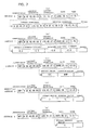
- FIG. 7 shows formats of waypoint data to be generated for each waypoint.
- “longitude information,” “latitude information,” “registration date,” and “registration time” as waypoint positional data are registered along with “approach coordinates (longitude, latitude)” as approach direction data and “departing coordinates (longitude, latitude)” as departing direction data.
- the approach direction data and the departing direction data are represented by differences [approach coordinates difference (longitude, latitude), departing coordinates difference (longitude, latitude)] between the positional coordinates of waypoint and the approach coordinates and departing coordinates of vehicle.
- these differences are only the data associated with the seconds among the coordinates information (degrees, minutes, and seconds) in many cases, so that the amount of the data associated with approach data and departing data can be reduced.
- the approach direction data and the departing direction data are registered as the absolute bearing (approach bearing) of approach coordinates and the absolute bearing (departing bearing) of departing coordinates as viewed from the waypoint (in the figure, SSE denotes South South East and WSW denotes West South West).
- SSE denotes South South East
- WSW denotes West South West
- all directions may be divided by 16 for example and each division may be represented in a numeric value.
- the amount of data associated with the approach direction data and the departing direction data can be reduced further.
- the relative bearing of approach direction and departing direction is represented as an approach departing bearing, thereby further reducing the amount of data.
- step S214 the departing flag F out is reset. If the departing flag F out is found not set in step S211, then the approach flag F in is reset in step S215.
- the above-mentioned processing is executed every time the vehicle approaches and passes each registered waypoint or every time a waypoint is registered, thereby adding the approach direction data and departing direction data to each waypoint.
- the following describes the approach direction navigation processing (step S11 shown in FIG. 5) based on the approach direction and departing direction data registered as above, with reference to the flowchart shown in FIG. 8.
- the "progress direction navigation processing" of the present embodiment is executed when traveling a return route and a second and subsequent approach routes.
- the navigation for the second and subsequent approach routes is effective when the vehicle of interest is used by a plurality of drivers and a next user is navigated to the same destination as the last user.
- step S301 whether or not a waypoint exists within 30 meters from the vehicle is determined. If no waypoint is found within 30 meters, then, in step S308, the direction of the waypoint to be passed next is displayed on the direction display section 6a of the display panel.
- step S302 If a waypoint is found within 30 meters, whether the backtrack mode is specified or not is determined in step S302. If the backtrack mode is found specified, then, in step S303, the approach direction data associated with the waypoint is retrieved from the auxiliary storage device 38. In step S304, the progress direction from the waypoint is displayed on the direction display section 6a on the basis of the above-mentioned approach direction data as shown in FIG. 10.
- step S302 If the backtrack mode is found not specified in step S302, then whether the departing direction data have been registered or not, or whether the travel this time is the second or subsequent approach route travel is determined in step S305.
- step S307 the progress direction from the waypoint is displayed on the direction display section 6a of the display panel 6 on the basis of the above-mentioned departing direction data as shown in FIG. 11.
- the data indicative of the approach direction to each waypoint on an approach path are registered and, when passing each waypoint on a return route, the vehicle is navigated in a predetermined progress direction from each waypoint on the basis of the registered approach direction data. Consequently, the vehicle on return route can be navigated in the normal progress direction along approach route.
- data indicative of the departing direction from a waypoint are registered for every waypoint on an approach route and, when passing each waypoint on the second or subsequent approach route, the vehicle is navigated in a predetermined progress direction from each waypoint on the basis of the registered departing direction data. Consequently, the vehicle can be navigated in the normal progress direction along the last route.
- the last fix buffer 32 is constituted by the pair of FIFO buffers A and B. It will be apparent that the last fix buffer 32 may also be constituted by three or more FIFO buffers.
- FIG. 12 shows the last fix buffer 32 which is constituted by three FIFO buffers A, B, and C.
- FIG. 13 is a flowchart describing a method of registering positional data into the last fix buffer 32.
- step S1 a 10-second timer of the CPU 34 starts.
- step S2 if the 10-second timer is found timed out, the procedure goes to step S3, in which the positional data (not registered for the first time) stored in each of storage areas A n (A 0 through A 30 ) of the buffer A of the last fix buffer 32 are shifted to each of the storage areas A n+1 .
- step S4 the current (most recent) positional data are stored in the top storage area A 0 of the buffer A.
- step S5 a 10-second counter T1 is incremented.
- step S6 if the 10-second counter T1 is found equal to or higher than 30 (namely, 5 minutes have passed), then, in step S7 the positional data stored in each of the storage areas B n of the buffer B are shifted to each of the storage areas B n+1 .
- step S8 the positional data 5 minutes before stored in the storage area A 30 of the buffer A are copied into the top storage area B 0 of the buffer B.
- step S9 the 10-second counter T1 is reset.
- step S91 a 5-minute counter T2 is incremented.
- step S92 if the 5-minute counter T2 is found equal to or higher than 6 (namely, 30 minutes have passed), then, in step S93, the positional data stored in each of the storage areas C n of the buffer C are shifted to each of the storage areas C n+1 .
- step S94 the positional data 30 minutes before stored in the storage area B 6 of the buffer B are copied into the top storage area C 0 of the buffer C.
- step S95 the counter T2 is reset.
- the storage area A 0 of the buffer A stores the most recent positional data
- the storage area A 1 stores the positional data 10 seconds before
- the storage area A 2 stores the positional data 20 seconds before, and so on and so forth.
- the storage area B 0 of the buffer B stores the positional data 5 minutes before
- the storage area B 1 stores the positional data 10 minutes before, and so on and so forth.
- the storage area C 0 of the buffer C stores the positional data 30 minutes before
- the storage area C 1 stores the positional data 60 minutes before, and so on and so forth.
- the positional data are registered for every predetermined interval of time. It will be apparent that the positional data may also be registered for every predetermined travel distance.
- FIG. 14 shows the last fix buffer 32 in which positional data are registered at every predetermined time.
- FIG. 15 is a flowchart describing a method of registering positional data are registered in the last fix buffer 32.
- step S1 a 10-meter (m) counter of the CPU 34 starts counting.
- step S2 if the 10-meter count is found overflowing, then the procedure goes to step S3, in which the positional data stored in each of the storage areas A n (A 0 through A 10 ) of the buffer A of the last fix buffer 32 are shifted to each of the storage areas A n+1 .
- step S4 the current (most recent) positional data are stored in the top storage area A 0 of the buffer A.
- step S5 the 10-meter counter T1 is incremented.
- step S6 if the 10-meter counter T1 is found equal to or higher than 10 (namely, 100 meters have been traveled), then, in step S7, the positional data stored in each of the storage areas B n of the buffer B are shifted to each of the storage areas B n+1 .
- step S8 the positional data stored in the storage area A 10 of the buffer A are copied into the stop storage area B 0 of the buffer B.
- step S9 the 10-meter counter T1 is reset.
- step S96 a 100-meter counter T2 is incremented.
- step S97 if the 100-meter counter T2 is found equal to or higher than 30 (namely, 3 kilometers have been traveled), then, in step S98, the positional data stored in each of the storage areas C n of the buffer C are shifted to each of the storage areas C n+1 .
- step S99 the positional data 3 kilometers before stored in the storage area B 30 of the buffer B are copied into the top storage area C 0 of the buffer C.
- step S95 the 100-meter counter T2 is reset.
- the storage area A 0 of the buffer A stores the most recent positional data
- the storage area A 1 stores the positional data 10 meters before
- the storage area A 2 stores the positional data 20 meters before, and so on and so forth.
- the storage area B 0 of the buffer B stores the positional data 100 meters before
- the storage area B 1 stores the positional data 200 meters before, and so on and so forth.
- the storage area C 0 of the buffer C stores the positional data 3 kilometers before
- the storage area C 1 stores the positional data 6 kilometers before, and so on and so forth.
- a movable body progress direction navigating apparatus for navigating a movable body in a predetermined progress direction, including: a track detector for continuously detecting positional data of a movable body to obtain a track thereof; a directional data generator for generating, on the basis of the locus of the movable body, at least one of approach directional data obtained when the movable body has entered into a predetermined via-point and departing directional data obtained when the movable body has departed from the via-point; a directional data storage for storing at least one of the approach direction data and the departing directional data in association with positional data of the via-point; and when the movable body has approached the via-point, a navigator for navigating the movable body in a predetermined progress direction, on the basis of at least one of the approach directional data or the departing directional data, whichever is stored in the directional data storage.
Abstract
A movable body progress direction navigating apparatus for navigating a movable body in a predetermined progress direction, including: a track detector (12,13,14) for continuously detecting positional data of a movable body to obtain a track thereof; a directional data generator (34) for generating, on the basis of the locus of the movable body, at least one of approach directional data obtained when the movable body has entered into a predetermined via-point and departing directional data obtained when the movable body has departed from the via-point; a directional data storage (32,38) for storing at least one of the approach direction data and the departing directional data in association with positional data of the via-point; and when the movable body has approached the via-point, a navigator for navigating the movable body in a predetermined progress direction, on the basis of at least one of the approach directional data or the departing directional data, whichever is stored in the directional data storage (32,38).
Description
- The present invention relates to a movable body progress direction navigating apparatus for navigating a movable body such as a vehicle or a walking human being for example into a predetermined progress direction and, more particularly, to a movable body progress direction navigating apparatus which, while being easily portable and small in size to facilitate the carriage especially on two-wheeled vehicles and pedestrians, correctly navigate them from a via-point into a predetermined direction.
- Navigation systems for displaying a optimum route from a start point to a destination by registering them beforehand are in wide use. In addition, a navigation system (a first related art technology) having a back-track mode known as product name "Magellan GPS 3000 Satellite Navigator" is sold (from December 1995 in Japan) from Mazellan Systems Japan Corporation, in which, halfway between a start point and destination, via-points are sequentially registered as "waypoints" and, in a return way, the registered waypoints are reversely followed to correctly reach the start point in the same route as the outward route. In this back-track mode, the distance and direction from each waypoint to another are displayed in each return route.
- In a technology (a second related art technology) disclosed in Japanese Patent Laid-open No. Hei 11-14390, when registering via-points beforehand, the longitude and latitude of each via-point are inputted as via-point data and, at the same time, the progress direction from each via-point is inputted as an absolute bearing, thereby displaying a progress direction of a movable body when it approaches each via-point.
- In the above-mentioned first related art technology, the current positions can be registered as via-point data (waypoints) during traveling; however, the approach direction to each waypoint and the departing direction therefrom cannot be registered. Consequently, as shown in FIG. 9, the progress direction represented by waypoint WP2 by the back track mode in return route becomes the direction of next (one point before in approach route) waypoint WP1 as shown in a dashed-line circle.
- Hence, as shown, unless the direction of the line segment connecting between adjacent waypoints WP2 and WP1 matches the direction of the road running from waypoint PW2 to waypoint PW1, a road of wrong direction displayed at waypoint WP2 may be indicated.
- Although the above-mentioned problem can be solved by registering many waypoints during traveling, it increases a memory capacity necessary for storing the registered waypoints, making such a solution unrealistic.
- In the above-mentioned second related art technology, the progress direction from each via-point inputted for approach route cannot be used for return route. Therefore, like the above-mentioned first related art technology, if the road status is as shown in FIG. 9, the movable body may be navigated along a wrong road.
- It is therefore an object of the present invention to solve the above-described problems, and to provide a movable body progress direction navigating apparatus which correctly navigates a movable body without requiring a large memory capacity.
- In order to attain the above object, the present invention is characterized in that a movable body progress direction navigating apparatus for navigating a movable body in a predetermined direction, including track detecting means for continuously detecting positional data of a movable body to obtain a track thereof; directional data generating means for generating, on the basis of the locus of the movable body, at least one of approach directional data obtained when the movable body has entered into a predetermined via-point and departing directional data obtained when the movable body has departed from the via-point; directional data storing means for storing at least one of the approach direction data and the departing directional data in association with positional data of the via-point; and when the movable body has approached the via-point, navigating means for navigating the movable body in a predetermined progress direction, on the basis of at least one of the approach directional data or the departing directional data, whichever is stored in the directional data storing means.
- According to the above-mentioned characteristics, the approach directional data and departing direction data of a movable body are stored in memory for each via-point, so that, when the movable body subsequently passes each via point again, the movable body can be correctly navigated in the normal direction from each via-point on the basis of the stored approach directional data and departing directional data.
- This invention will be described in further detail by way of example with reference to the accompanying drawings, in which:
- FIG. 1 is a view of a display panel of a movable body incorporating a progress direction navigating system according to the invention.
- FIGS. 2(a) and 2(b) are diagrams explaining the function of a remaining distance bar graph.
- FIG. 3 is a block diagram illustrating a circuit configuration of a meter unit.
- FIG. 4 is a diagram illustrating a first embodiment of a last fix buffer.
- FIG. 5 is a flowchart describing an operation of the present embodiment.
- FIG. 6 is a flowchart describing an operation of waypoint registration processing.
- FIG. 7(a) to (e) are diagrams illustrating examples of waypoint data formats.
- FIG. 8 is a flowchart describing an operation of progress direction navigation processing.
- FIG. 9 is a diagram illustrating a drawback in related art.
- FIG. 10 is a diagram illustrating a navigation method in return route.
- FIG. 11 is a diagram illustrating a navigation method for re-traveling an approach route.
- FIG. 12 is a diagram illustrating a configuration of the second embodiment of the last fix buffer.
- FIG. 13 is a flowchart describing a method of registering positional data into the last fix buffer shown in FIG. 12.
- FIG. 14 is a diagram illustrating a configuration of the third embodiment of the last fix buffer.
- FIG. 15 is a flowchart describing a method of registering positional data into the last fix buffer shown in FIG. 14.
-
- Now, referring to FIG. 1, there is shown a front view of an exemplary display panel of a movable body incorporating a progress direction navigating system according to the invention. In the present invention, the movable body is embodied in a vehicle.
- A
display panel 6 has a direction display section 6a for indicating the direction of a destination where the progress direction (N) of the vehicle is above, a speed meter 6b, a remaining distance bar graph 6c for indicating a distance to the destination to be traveled in a bar graph, a remaining distance meter 6d for indicating a distance to be traveled in a numeric value, a remaining distance set button 6e, a distance meter 6f for indicating a total travel distance of the vehicle, and a time meter 6g for indicating a total travel time. - The direction display section 6a can show 8 directions with intervals of 45 degrees. The remaining distance bar graph 6c has a
reference distance marker equidistant scales 11 for example. When a destination is set (at the time of start), the remaining distance bar graph 6c is colored (in blue for example) full scale to the right from thereference distance marker 10 and a straight line from the current position to the destination is shown in a numeric value. For example, if a total distance from the current position to the destination is 500 km, the bar graph is displayed full scale as shown in FIG. 2(a) and a remaining distance of 50 km is displayed in numeric value on the remaining distance meter 6d. - If the vehicle approaches the destination by 30 km for example, the remaining distance bar graph 6c turns off up to the third scale from the
reference distance marker 10, turning off the section to the right of the third scale. The remaining distance meter 6d shows a remaining distance of 20 km in numeric value. - FIG. 3 is a block diagram illustrating a circuit configuration of the above-mentioned meter unit. A GPS (Global Positioning System) 14 receives signals from artificial satellites to measure the current position (longitude and latitude) of the vehicle. A
bearing sensor 12 detects the current position and bearing of the vehicle. Adistance sensor 13 detects a travel distance of the vehicle. TheGPS 14, thebearing sensor 12, and thedistance sensor 13 are connected to asystem bus 33 via aninterface circuit group 31. - The
operator panel 22 has a scroll button for use in setting a destination for example and operator buttons for setting waypoints and backtrack mode to be described later and is connected to thesystem bus 33 via theinterface circuit 35. - On the basis of the information captured from the
GPS 14, thebearing sensor 12, and thedistance sensor 12 and a control program previously stored in aROM 36, aCPU 34 obtains the direction of the destination relative to the current vehicle position, a distance from the current position to the destination, and so on, outputting the obtained information to thedisplay panel 6 via adisplay controller 39. ARAM 37 provides a work area for theCPU 34. - An
auxiliary storage device 38 is an easily-detachable storage medium, such as an IC card. Alast fix buffer 32 is constituted by a pair of FIFO buffers A and B as shown in FIG. 4 in which the positional data indicative of current position detected by theGPS 14 are stored in a periodic manner. - The following describes an operation of the present embodiment with reference to the flowcharts shown in FIGS. 5, 6, and 8.
- When the system is activated, a one-minute timer of the
CPU 34 starts in step S1 shown in FIG. 5. In step S2, whether the one-minute timer has timed out or not is determined. If the one-minute timer is found not timed out, "waypoint registration processing" of step S10 and "progress direction navigation processing" of step S11 to be described later are executed and then the procedure returns to step S1. - If the one-minute timer is found timed out, then the procedure goes to step S3, in which the positional data stored in each of storage areas An (A0 through A10) in the buffer A of the
last fix buffer 32 are shifted to storage areas An+1. In step S4, the current (most recent) positional data are stored in top storage area A0 of the buffer A. - In step S5, count value T of a 10-minute timer is incremented. In step S6, whether count value T is equal to or higher than 10 (namely, whether 10 minutes have passed) or not is determined. For the first time, count value T is less than 10, so that the procedure goes to step S10. In step S10, "waypoint registration processing" shown in the flowchart of FIG. 6 is executed.
- A waypoint is a via-point for which its positional data are previously registered by the user beforehand or a via point for which its positional data are registered by the user when the vehicle passes this via-point. The waypoint is stored in the
auxiliary storage device 38. - In step S201 of FIG. 6, whether a waypoint exists within 30 meters for example relative to the vehicle is determined on the basis of the registered waypoint and the positional data of the current position. When the vehicle has entered an area located within 30 meters from the registered waypoint or when a waypoint is newly registered at the current position by following a predetermined waypoint registering operation, it is determined that the waypoint exists within 30 meters and the procedure goes to step S202; otherwise, the procedure goes to step S210.
- If no waypoint exists within 30 meters, then an approach flag Fin, which will be detailed later, is referenced in step S210. If the approach flag Fin is found in a reset state (= 0), this processing comes to an end, upon which the procedure goes to step S11 shown in FIG. 5, in which "progress direction navigation processing" to be described later is executed, upon which the procedure returns to step S1.
- The above-mentioned processing operations are repeated. Then, if count value T of the 10-minutes timer is found to be equal to or higher than 10, then, in step S7, the positional data (unregistered first) stored in each of storage areas Bn of the buffer B is shifted to storage area Bn+1. In step S8, the
positional data 10 minutes before stored in the storage area A10 of the buffer A are copied into the top storage area B0 of the buffer B. In step S9, count value T of the 10-minutes timer is reset. - Namely, in the present embodiment, the most recent positional data are stored in storage area A0 of the buffer A, the
positional data 1 minute before are stored in storage area A1, thepositional data 2 minutes before are stored in storage area A2, and so on. Thepositional data 10 minutes before are stored in storage area B0 of the buffer B, thepositional data 20 minutes before are stored in storage area B1, thepositional data 30 minutes before are stored in storage area B2, and so on. - Then, when the vehicle approaches the registered waypoint or a waypoint is newly registered and this is detected in step S201 of FIG. 6, the procedure goes to step S202.
- In step S202, the approach flag Fin indicating that the vehicle has entered in an area within 30 meters from the waypoint is set. In step S203, whether "approach direction data" have already been registered with respect to this waypoint is determined. In the present embodiment, the approach direction data indicate the direction in which the vehicle approaches each waypoint.
- If the approach direction data are found not registered, the approach direction data are computed in step S204. In step S205, the computed data are stored in the
auxiliary storage device 38 as attribute data of the positional data of the waypoint. - If the movable body has approached the registered waypoint, the approach direction data are computed on the basis of the positional data of the current position, which is the current approach point, and the positional data of the waypoint. On the contrary, if the waypoint is newly registered at a via-point, the positional data of a
position 30 meters for example before the via-point are read from the buffer A or B of thelast fix buffer 32 as the positional data of a position predetermined interval before the via-point and the approach direction data are computed on the basis of the retrieved positional data and the positional data of the waypoint. - As will be described with reference to FIG. 7, the approach direction data is obtained as the longitude/latitude of current position (method 1), a difference in longitude/latitude coordinates between current position and waypoint (method 2), or a bearing of waypoint as viewed from current position. The obtained approach position data are stored as associated with the positional data of waypoint.
- In step S206, whether "departing direction data" have already been registered or not is determined with respect to the waypoint. The departing direction data in this embodiment denote the data representing a departing direction from the waypoint of the vehicle.
- If the departing direction data are found not registered, a departing flag Fout is set in step S207; if the departing direction data are found registered, the departing flag Fout is reset in step S208. Namely, this departing flag Fout is set when the departing direction data have not been registered although the approach direction data have been registered.
- Subsequently, when the vehicle has passed the waypoint and it is determined that the vehicle has departed 30 meters or more away from the waypoint in step S201, the approach flag Fin is referenced in step S210. If the approach flag Fin is found set and the departing flag Fout is found set in step S211, then the departing direction data are computed in the same manner as above on the basis of the current positional data and the position data of the waypoint in step S212. The obtained departing direction data are stored in step S213.
- FIG. 7 shows formats of waypoint data to be generated for each waypoint. In the first method shown in FIG. 7(a), "longitude information," "latitude information," "registration date," and "registration time" as waypoint positional data are registered along with "approach coordinates (longitude, latitude)" as approach direction data and "departing coordinates (longitude, latitude)" as departing direction data.
- In the second method shown in FIG. 7(b), the approach direction data and the departing direction data are represented by differences [approach coordinates difference (longitude, latitude), departing coordinates difference (longitude, latitude)] between the positional coordinates of waypoint and the approach coordinates and departing coordinates of vehicle. According to this second method, these differences are only the data associated with the seconds among the coordinates information (degrees, minutes, and seconds) in many cases, so that the amount of the data associated with approach data and departing data can be reduced.
- In the third method shown in FIG. 7(c), the approach direction data and the departing direction data are registered as the absolute bearing (approach bearing) of approach coordinates and the absolute bearing (departing bearing) of departing coordinates as viewed from the waypoint (in the figure, SSE denotes South South East and WSW denotes West South West). It should be noted that, as shown in FIG. 7(d), all directions may be divided by 16 for example and each division may be represented in a numeric value. According to the third method, the amount of data associated with the approach direction data and the departing direction data can be reduced further.
- In the fourth method shown in FIG. 7(e), the relative bearing of approach direction and departing direction is represented as an approach departing bearing, thereby further reducing the amount of data.
- Referring to FIG. 6 again, in step S214, the departing flag Fout is reset. If the departing flag Fout is found not set in step S211, then the approach flag Fin is reset in step S215.
- Subsequently, the above-mentioned processing is executed every time the vehicle approaches and passes each registered waypoint or every time a waypoint is registered, thereby adding the approach direction data and departing direction data to each waypoint.
- The following describes the approach direction navigation processing (step S11 shown in FIG. 5) based on the approach direction and departing direction data registered as above, with reference to the flowchart shown in FIG. 8. The "progress direction navigation processing" of the present embodiment is executed when traveling a return route and a second and subsequent approach routes. The navigation for the second and subsequent approach routes is effective when the vehicle of interest is used by a plurality of drivers and a next user is navigated to the same destination as the last user.
- In step S301, whether or not a waypoint exists within 30 meters from the vehicle is determined. If no waypoint is found within 30 meters, then, in step S308, the direction of the waypoint to be passed next is displayed on the direction display section 6a of the display panel.
- If a waypoint is found within 30 meters, whether the backtrack mode is specified or not is determined in step S302. If the backtrack mode is found specified, then, in step S303, the approach direction data associated with the waypoint is retrieved from the
auxiliary storage device 38. In step S304, the progress direction from the waypoint is displayed on the direction display section 6a on the basis of the above-mentioned approach direction data as shown in FIG. 10. - If the backtrack mode is found not specified in step S302, then whether the departing direction data have been registered or not, or whether the travel this time is the second or subsequent approach route travel is determined in step S305.
- If the departing direction data have been registered, then the departing direction data associated with the waypoint are retrieved from the auxiliary storage device in step S306. In step S307, the progress direction from the waypoint is displayed on the direction display section 6a of the
display panel 6 on the basis of the above-mentioned departing direction data as shown in FIG. 11. - According to the present embodiment, the data indicative of the approach direction to each waypoint on an approach path are registered and, when passing each waypoint on a return route, the vehicle is navigated in a predetermined progress direction from each waypoint on the basis of the registered approach direction data. Consequently, the vehicle on return route can be navigated in the normal progress direction along approach route.
- Further, according to the present embodiment, data indicative of the departing direction from a waypoint are registered for every waypoint on an approach route and, when passing each waypoint on the second or subsequent approach route, the vehicle is navigated in a predetermined progress direction from each waypoint on the basis of the registered departing direction data. Consequently, the vehicle can be navigated in the normal progress direction along the last route.
- In the above-mentioned embodiment, the
last fix buffer 32 is constituted by the pair of FIFO buffers A and B. It will be apparent that thelast fix buffer 32 may also be constituted by three or more FIFO buffers. - FIG. 12 shows the
last fix buffer 32 which is constituted by three FIFO buffers A, B, and C. FIG. 13 is a flowchart describing a method of registering positional data into thelast fix buffer 32. - In step S1, a 10-second timer of the
CPU 34 starts. In step S2, if the 10-second timer is found timed out, the procedure goes to step S3, in which the positional data (not registered for the first time) stored in each of storage areas An (A0 through A30) of the buffer A of thelast fix buffer 32 are shifted to each of the storage areas An+1. In step S4, the current (most recent) positional data are stored in the top storage area A0 of the buffer A. - In step S5, a 10-second counter T1 is incremented. In step S6, if the 10-second counter T1 is found equal to or higher than 30 (namely, 5 minutes have passed), then, in step S7 the positional data stored in each of the storage areas Bn of the buffer B are shifted to each of the storage areas Bn+1. In step S8, the
positional data 5 minutes before stored in the storage area A30 of the buffer A are copied into the top storage area B0 of the buffer B. In step S9, the 10-second counter T1 is reset. - In step S91, a 5-minute counter T2 is incremented. In step S92, if the 5-minute counter T2 is found equal to or higher than 6 (namely, 30 minutes have passed), then, in step S93, the positional data stored in each of the storage areas Cn of the buffer C are shifted to each of the storage areas Cn+1. In step S94, the
positional data 30 minutes before stored in the storage area B6 of the buffer B are copied into the top storage area C0 of the buffer C. In step S95, the counter T2 is reset. - Namely, in the present embodiment, the storage area A0 of the buffer A stores the most recent positional data, the storage area A1 stores the
positional data 10 seconds before, the storage area A2 stores thepositional data 20 seconds before, and so on and so forth.
Likewise, the storage area B0 of the buffer B stores thepositional data 5 minutes before, the storage area B1 stores thepositional data 10 minutes before, and so on and so forth. The storage area C0 of the buffer C stores thepositional data 30 minutes before, the storage area C1 stores the positional data 60 minutes before, and so on and so forth. - In the above-mentioned present embodiment, the positional data are registered for every predetermined interval of time. It will be apparent that the positional data may also be registered for every predetermined travel distance.
- FIG. 14 shows the
last fix buffer 32 in which positional data are registered at every predetermined time. FIG. 15 is a flowchart describing a method of registering positional data are registered in thelast fix buffer 32. - In step S1, a 10-meter (m) counter of the
CPU 34 starts counting. In step S2, if the 10-meter count is found overflowing, then the procedure goes to step S3, in which the positional data stored in each of the storage areas An (A0 through A10) of the buffer A of thelast fix buffer 32 are shifted to each of the storage areas An+1. In step S4, the current (most recent) positional data are stored in the top storage area A0 of the buffer A. - In step S5, the 10-meter counter T1 is incremented. In step S6, if the 10-meter counter T1 is found equal to or higher than 10 (namely, 100 meters have been traveled), then, in step S7, the positional data stored in each of the storage areas Bn of the buffer B are shifted to each of the storage areas Bn+1. In step S8, the positional data stored in the storage area A10 of the buffer A are copied into the stop storage area B0 of the buffer B. In step S9, the 10-meter counter T1 is reset.
- In step S96, a 100-meter counter T2 is incremented. In step S97, if the 100-meter counter T2 is found equal to or higher than 30 (namely, 3 kilometers have been traveled), then, in step S98, the positional data stored in each of the storage areas Cn of the buffer C are shifted to each of the storage areas Cn+1. In step S99, the
positional data 3 kilometers before stored in the storage area B30 of the buffer B are copied into the top storage area C0 of the buffer C. In step S95, the 100-meter counter T2 is reset. - Namely, in the present embodiment, the storage area A0 of the buffer A stores the most recent positional data, the storage area A1 stores the
positional data 10 meters before, the storage area A2 stores thepositional data 20 meters before, and so on and so forth. Likewise, the storage area B0 of the buffer B stores thepositional data 100 meters before, the storage area B1 stores the positional data 200 meters before, and so on and so forth. The storage area C0 of the buffer C stores thepositional data 3 kilometers before, the storage area C1 stores thepositional data 6 kilometers before, and so on and so forth. - As described and according to the invention, the following effects can be achieved.
- (1) The data indicative of the approach direction to a waypoint are registered for every waypoint in an approach route and when passing each waypoint on a return route, the vehicle is navigated in a predetermined progress direction from each waypoint on the basis of the registered approach direction data. Consequently, the vehicle on return route can be navigated in the normal progress direction along approach route.
- (2) The data indicative of the departing direction from a waypoint are registered for every waypoint on an approach route and, when passing each waypoint on the second or subsequent approach route, the vehicle is navigated in a predetermined progress direction from each waypoint on the basis of the registered departing direction data. Consequently, the vehicle can be navigated in the normal progress direction along the last route.
- (3) The movable body's travel routes before and after each waypoint are controlled by the data indicative of the approach direction to the waypoint of interest and/or the data indicative of the departing direction from the waypoint of interest. Consequently, the vehicle can be correctly navigated with a small storage capacity.
-
- In summary it is an object to provide a movable body progress direction navigating apparatus capable of correct navigation without requiring a large storage capacity.
- It is provided a movable body progress direction navigating apparatus for navigating a movable body in a predetermined progress direction, including: a track detector for continuously detecting positional data of a movable body to obtain a track thereof; a directional data generator for generating, on the basis of the locus of the movable body, at least one of approach directional data obtained when the movable body has entered into a predetermined via-point and departing directional data obtained when the movable body has departed from the via-point; a directional data storage for storing at least one of the approach direction data and the departing directional data in association with positional data of the via-point; and when the movable body has approached the via-point, a navigator for navigating the movable body in a predetermined progress direction, on the basis of at least one of the approach directional data or the departing directional data, whichever is stored in the directional data storage.
Claims (11)
- A movable body progress direction navigating apparatus for navigating a movable body in a predetermined direction, comprising:track detecting means (12, 13, 14) for continuously detecting positional data of a movable body to obtain a track thereof;directional data generating means (34) for generating, on the basis of said locus of said movable body, at least one of approach directional data obtained when said movable body has entered into a predetermined via-point (WP1, WP2) and departing directional data obtained when said movable body has departed from said via-point (WP1, WP2);directional data storing means (32, 38) for storing at least one of said approach direction data and said departing directional data in association with positional data of said via-point (WP1, WP2); andwhen said movable body has approached said via-point (WP1, WP2), navigating means (6a) for navigating said movable body in a predetermined progress direction, on the basis of at least one of said approach directional data or said departing directional data, whichever is stored in said directional data storing means (32, 38).
- A movable body progress direction navigating apparatus according to claim 1, wherein said via-point (WP1, WP2) is a current position of said movable body at the point of time when a predetermined registration operation has been made.
- A movable body progress direction navigating apparatus according to claim 1, wherein said via-point (WP1, WP2) is a predetermined position which was registered beforehand.
- A movable body progress direction navigating apparatus according to any one of claims 1 through 3, wherein said directional data generating means (34) computes said approach directional data on the basis of positional data of said movable body at a point, which is a predetermined interval before said movable body enters a predetermined via-point (WP1, WP2), and positional data of said predetermined via-point (WP1, WP2).
- A movable body progress direction navigating apparatus according to any one of claims 1 through 3, wherein said directional data generating means (34), on the basis of positional data of said movable body at a point which is a predetermined interval away from a predetermined via-point (WP1, WP2) and positional data of said predetermined via point (WP1, WP2), computes said departing directional data.
- A movable body progress direction navigating apparatus according to claim 4, wherein said directional data generating means (34) uses, as said approach directional data, a difference between coordinates of said predetermined via-point (WP1, WP2) and coordinates of said movable body at a point which is said predetermined interval short of said via-point (WP1, WP2).
- A movable body progress direction navigating apparatus according to claim 4, wherein said directional data generating means (34) uses, as said approach directional data, a bearing at a point which is said predetermined interval short of said predetermined via-point (WP1, WP2).
- A movable body progress direction navigating apparatus according to claim 4, wherein said directional data generating means (34) uses, as said approach direction data, a relative bearing of a point which is short of said predetermined interval relative to a point which is away by said predetermined interval.
- A movable body progress direction navigating apparatus according to claim 5, wherein said directional data generating means (34) uses, as said departing directional data, a difference between coordinates of said predetermined via-point and coordinates of said movable body at a point which is departed from said predetermined via-point (WP1, WP2) by said predetermined interval.
- A movable body progress direction navigating apparatus according to claim 5, wherein said directional data generating means (34) uses, as said departing directional data, a bearing of a point which is departed away from said predetermined via-point (WP1, WP2) by said predetermined interval.
- A movable body progress direction navigating apparatus according to claim 5, wherein said directional data generating means (34) uses, as said departing directional data, a relative bearing of a point which is away, by said predetermined interval, from said point which is short of said predetermined interval by said predetermined interval.
Applications Claiming Priority (2)
| Application Number | Priority Date | Filing Date | Title |
|---|---|---|---|
| JP2001029495A JP4557238B2 (en) | 2001-02-06 | 2001-02-06 | Directional guidance device for motorcycles |
| JP2001029495 | 2001-02-06 |
Publications (2)
| Publication Number | Publication Date |
|---|---|
| EP1229306A1 true EP1229306A1 (en) | 2002-08-07 |
| EP1229306B1 EP1229306B1 (en) | 2008-09-10 |
Family
ID=18893838
Family Applications (1)
| Application Number | Title | Priority Date | Filing Date |
|---|---|---|---|
| EP02002480A Expired - Lifetime EP1229306B1 (en) | 2001-02-06 | 2002-02-01 | Movable body progress direction navigating apparatus |
Country Status (10)
| Country | Link |
|---|---|
| US (1) | US6662102B2 (en) |
| EP (1) | EP1229306B1 (en) |
| JP (1) | JP4557238B2 (en) |
| CN (1) | CN1254660C (en) |
| AU (1) | AU784429B2 (en) |
| BR (1) | BR0200340A (en) |
| CA (1) | CA2369441C (en) |
| DE (1) | DE60228778D1 (en) |
| MY (1) | MY133249A (en) |
| TW (1) | TW542903B (en) |
Families Citing this family (14)
| Publication number | Priority date | Publication date | Assignee | Title |
|---|---|---|---|---|
| JP2003065784A (en) * | 2001-08-28 | 2003-03-05 | Vertex Standard Co Ltd | Gps navigation device |
| JP2004212146A (en) * | 2002-12-27 | 2004-07-29 | Sumitomo Precision Prod Co Ltd | Dead reckoning navigation system and dead reckoning navigation for walker |
| TW200519654A (en) * | 2003-12-15 | 2005-06-16 | Compass Systems Corp | Method of constructing personal journey diary |
| JP4629989B2 (en) * | 2004-03-26 | 2011-02-09 | 株式会社ゼンリン | Route guidance device |
| US8788192B2 (en) * | 2005-05-18 | 2014-07-22 | International Business Machines Corporation | Navigation method, system or service and computer program product |
| ATE554367T1 (en) * | 2008-05-09 | 2012-05-15 | Research In Motion Ltd | PREDICTIVE DOWNLOADING OF MAP DATA |
| US8606458B2 (en) * | 2008-12-12 | 2013-12-10 | Fleetcor Technologies Operating Company, Llc | Navigation system having mileage mechanism and method of operation thereof |
| US9062982B2 (en) * | 2008-12-15 | 2015-06-23 | Blackberry Limited | Pre-loading waypoint data |
| TWI395970B (en) * | 2009-08-10 | 2013-05-11 | Ind Tech Res Inst | Method and apparatus for positioning mobile device |
| US9696176B2 (en) * | 2011-01-06 | 2017-07-04 | Ford Global Technologies, Llc | Information display system and method |
| US8755994B2 (en) * | 2011-01-06 | 2014-06-17 | Ford Global Technologies, Llc | Information display system and method |
| JP6035915B2 (en) * | 2012-07-05 | 2016-11-30 | カシオ計算機株式会社 | Direction display device and direction display system |
| US10168171B2 (en) * | 2013-10-31 | 2019-01-01 | Tomtom Navigation B.V. | Apparatus and methods of determining paths through an electronic map |
| JP7420314B1 (en) * | 2022-04-27 | 2024-01-23 | 三菱電機株式会社 | Mobile object control device, mobile object control method, and mobile object control program |
Citations (4)
| Publication number | Priority date | Publication date | Assignee | Title |
|---|---|---|---|---|
| US4403291A (en) * | 1979-10-11 | 1983-09-06 | Siemens Aktiengesellschaft | Self-sufficient navigation device for street vehicles |
| EP0762361A1 (en) * | 1995-08-25 | 1997-03-12 | Aisin Aw Co., Ltd. | Navigation system for vehicles |
| EP0767358A1 (en) * | 1995-10-04 | 1997-04-09 | Aisin Aw Co., Ltd. | Vehicle navigation system |
| EP0782118A1 (en) * | 1995-12-26 | 1997-07-02 | Aisin Aw Co., Ltd. | Navigation system for vehicles |
Family Cites Families (9)
| Publication number | Priority date | Publication date | Assignee | Title |
|---|---|---|---|---|
| JPH05187882A (en) * | 1992-01-09 | 1993-07-27 | Daihatsu Motor Co Ltd | Display control method of navigation system |
| JPH0789063B2 (en) * | 1993-04-30 | 1995-09-27 | マスプロ電工株式会社 | Vehicle driving route guidance device |
| JP3411467B2 (en) * | 1997-04-04 | 2003-06-03 | 松下電器産業株式会社 | Route selection method and system |
| JPH1114390A (en) * | 1997-06-20 | 1999-01-22 | Yamaha Motor Co Ltd | Route guiding method by navigation device |
| JPH1137779A (en) * | 1997-07-22 | 1999-02-12 | Nissan Motor Co Ltd | Information presentation apparatus |
| JPH11160093A (en) * | 1997-11-28 | 1999-06-18 | Alpine Electron Inc | Intersection guide system |
| US6266614B1 (en) * | 1997-12-24 | 2001-07-24 | Wendell Alumbaugh | Travel guide |
| US6199010B1 (en) * | 1998-05-04 | 2001-03-06 | Lucent Technologies, Inc. | Wireless telecommunications system that provides navigational assistance to travelers |
| JP2000283781A (en) * | 1999-03-31 | 2000-10-13 | Matsushita Electric Ind Co Ltd | Car navigation system and guide/display method therefor |
-
2001
- 2001-02-06 JP JP2001029495A patent/JP4557238B2/en not_active Expired - Fee Related
-
2002
- 2002-01-15 TW TW091100494A patent/TW542903B/en not_active IP Right Cessation
- 2002-01-17 AU AU10223/02A patent/AU784429B2/en not_active Ceased
- 2002-01-25 CA CA002369441A patent/CA2369441C/en not_active Expired - Fee Related
- 2002-02-01 DE DE60228778T patent/DE60228778D1/en not_active Expired - Lifetime
- 2002-02-01 EP EP02002480A patent/EP1229306B1/en not_active Expired - Lifetime
- 2002-02-04 MY MYPI20020369A patent/MY133249A/en unknown
- 2002-02-05 CN CNB021035350A patent/CN1254660C/en not_active Expired - Fee Related
- 2002-02-06 BR BR0200340-6A patent/BR0200340A/en not_active Application Discontinuation
- 2002-02-06 US US10/066,634 patent/US6662102B2/en not_active Expired - Lifetime
Patent Citations (4)
| Publication number | Priority date | Publication date | Assignee | Title |
|---|---|---|---|---|
| US4403291A (en) * | 1979-10-11 | 1983-09-06 | Siemens Aktiengesellschaft | Self-sufficient navigation device for street vehicles |
| EP0762361A1 (en) * | 1995-08-25 | 1997-03-12 | Aisin Aw Co., Ltd. | Navigation system for vehicles |
| EP0767358A1 (en) * | 1995-10-04 | 1997-04-09 | Aisin Aw Co., Ltd. | Vehicle navigation system |
| EP0782118A1 (en) * | 1995-12-26 | 1997-07-02 | Aisin Aw Co., Ltd. | Navigation system for vehicles |
Also Published As
| Publication number | Publication date |
|---|---|
| BR0200340A (en) | 2002-10-08 |
| TW542903B (en) | 2003-07-21 |
| JP2002228473A (en) | 2002-08-14 |
| JP4557238B2 (en) | 2010-10-06 |
| MY133249A (en) | 2007-10-31 |
| AU1022302A (en) | 2002-08-08 |
| US20020107635A1 (en) | 2002-08-08 |
| DE60228778D1 (en) | 2008-10-23 |
| AU784429B2 (en) | 2006-03-30 |
| CN1369691A (en) | 2002-09-18 |
| CA2369441C (en) | 2005-11-15 |
| CA2369441A1 (en) | 2002-08-06 |
| US6662102B2 (en) | 2003-12-09 |
| EP1229306B1 (en) | 2008-09-10 |
| CN1254660C (en) | 2006-05-03 |
Similar Documents
| Publication | Publication Date | Title |
|---|---|---|
| US7127350B2 (en) | Navigation apparatus | |
| EP0524814B1 (en) | Navigation device | |
| US7398155B2 (en) | Car navigation system | |
| US5842147A (en) | Navigation display device which indicates goal and route direction information | |
| US20080021638A1 (en) | Navigation system | |
| EP1233251A2 (en) | Navigation system | |
| JP4148232B2 (en) | Route guidance device | |
| EP1229306B1 (en) | Movable body progress direction navigating apparatus | |
| US5473324A (en) | Map display apparatus | |
| US6253153B1 (en) | Vehicle navigation system and method | |
| US7124025B2 (en) | Vehicular navigation device | |
| US7346450B2 (en) | Vehicle navigation apparatus for controlling map-matching areas | |
| JPH09222330A (en) | Navigation device | |
| JP3407894B2 (en) | Vehicle guidance system | |
| JP4822938B2 (en) | Navigation device | |
| JP2544855B2 (en) | Vehicle guidance device | |
| JPH04213019A (en) | Position-detecting-accuracy judging method and vehicle guiding apparatus using method thereof | |
| JP3064752B2 (en) | Route guidance device for vehicles | |
| JP3653121B2 (en) | In-vehicle route search device and recommended route display method | |
| JPS6366411A (en) | Vehicle path guide apparatus | |
| EP0731337B1 (en) | Navigation device | |
| JP2913857B2 (en) | Destination guidance device used for vehicle navigation | |
| JPH04109116A (en) | Running path display device | |
| JP3176106B2 (en) | Travel guidance device for vehicles | |
| JP2697356B2 (en) | Navigation system for moving objects |
Legal Events
| Date | Code | Title | Description |
|---|---|---|---|
| PUAI | Public reference made under article 153(3) epc to a published international application that has entered the european phase |
Free format text: ORIGINAL CODE: 0009012 |
|
| AK | Designated contracting states |
Kind code of ref document: A1 Designated state(s): AT BE CH CY DE DK ES FI FR GB GR IE IT LI LU MC NL PT SE TR |
|
| AX | Request for extension of the european patent |
Free format text: AL;LT;LV;MK;RO;SI |
|
| 17P | Request for examination filed |
Effective date: 20020730 |
|
| AKX | Designation fees paid |
Designated state(s): DE FR IT |
|
| 17Q | First examination report despatched |
Effective date: 20070718 |
|
| GRAP | Despatch of communication of intention to grant a patent |
Free format text: ORIGINAL CODE: EPIDOSNIGR1 |
|
| GRAS | Grant fee paid |
Free format text: ORIGINAL CODE: EPIDOSNIGR3 |
|
| GRAA | (expected) grant |
Free format text: ORIGINAL CODE: 0009210 |
|
| AK | Designated contracting states |
Kind code of ref document: B1 Designated state(s): DE FR IT |
|
| REF | Corresponds to: |
Ref document number: 60228778 Country of ref document: DE Date of ref document: 20081023 Kind code of ref document: P |
|
| PLBE | No opposition filed within time limit |
Free format text: ORIGINAL CODE: 0009261 |
|
| STAA | Information on the status of an ep patent application or granted ep patent |
Free format text: STATUS: NO OPPOSITION FILED WITHIN TIME LIMIT |
|
| 26N | No opposition filed |
Effective date: 20090611 |
|
| PGFP | Annual fee paid to national office [announced via postgrant information from national office to epo] |
Ref country code: FR Payment date: 20110218 Year of fee payment: 10 Ref country code: IT Payment date: 20110219 Year of fee payment: 10 |
|
| REG | Reference to a national code |
Ref country code: DE Ref legal event code: R084 Ref document number: 60228778 Country of ref document: DE Effective date: 20111128 |
|
| REG | Reference to a national code |
Ref country code: FR Ref legal event code: ST Effective date: 20121031 |
|
| PG25 | Lapsed in a contracting state [announced via postgrant information from national office to epo] |
Ref country code: IT Free format text: LAPSE BECAUSE OF NON-PAYMENT OF DUE FEES Effective date: 20120201 |
|
| PG25 | Lapsed in a contracting state [announced via postgrant information from national office to epo] |
Ref country code: FR Free format text: LAPSE BECAUSE OF NON-PAYMENT OF DUE FEES Effective date: 20120229 |
|
| PGFP | Annual fee paid to national office [announced via postgrant information from national office to epo] |
Ref country code: DE Payment date: 20160127 Year of fee payment: 15 |
|
| REG | Reference to a national code |
Ref country code: DE Ref legal event code: R119 Ref document number: 60228778 Country of ref document: DE |
|
| PG25 | Lapsed in a contracting state [announced via postgrant information from national office to epo] |
Ref country code: DE Free format text: LAPSE BECAUSE OF NON-PAYMENT OF DUE FEES Effective date: 20170901 |