EP1229223B1 - Engine exhaust emission purification device - Google Patents
Engine exhaust emission purification device Download PDFInfo
- Publication number
- EP1229223B1 EP1229223B1 EP02002551A EP02002551A EP1229223B1 EP 1229223 B1 EP1229223 B1 EP 1229223B1 EP 02002551 A EP02002551 A EP 02002551A EP 02002551 A EP02002551 A EP 02002551A EP 1229223 B1 EP1229223 B1 EP 1229223B1
- Authority
- EP
- European Patent Office
- Prior art keywords
- regeneration
- filter
- engine
- purification device
- exhaust gas
- Prior art date
- Legal status (The legal status is an assumption and is not a legal conclusion. Google has not performed a legal analysis and makes no representation as to the accuracy of the status listed.)
- Expired - Lifetime
Links
Images


Classifications
-
- F—MECHANICAL ENGINEERING; LIGHTING; HEATING; WEAPONS; BLASTING
- F02—COMBUSTION ENGINES; HOT-GAS OR COMBUSTION-PRODUCT ENGINE PLANTS
- F02D—CONTROLLING COMBUSTION ENGINES
- F02D41/00—Electrical control of supply of combustible mixture or its constituents
- F02D41/02—Circuit arrangements for generating control signals
- F02D41/14—Introducing closed-loop corrections
- F02D41/1438—Introducing closed-loop corrections using means for determining characteristics of the combustion gases; Sensors therefor
- F02D41/1444—Introducing closed-loop corrections using means for determining characteristics of the combustion gases; Sensors therefor characterised by the characteristics of the combustion gases
- F02D41/1445—Introducing closed-loop corrections using means for determining characteristics of the combustion gases; Sensors therefor characterised by the characteristics of the combustion gases the characteristics being related to the exhaust flow
-
- F—MECHANICAL ENGINEERING; LIGHTING; HEATING; WEAPONS; BLASTING
- F01—MACHINES OR ENGINES IN GENERAL; ENGINE PLANTS IN GENERAL; STEAM ENGINES
- F01N—GAS-FLOW SILENCERS OR EXHAUST APPARATUS FOR MACHINES OR ENGINES IN GENERAL; GAS-FLOW SILENCERS OR EXHAUST APPARATUS FOR INTERNAL-COMBUSTION ENGINES
- F01N3/00—Exhaust or silencing apparatus having means for purifying, rendering innocuous, or otherwise treating exhaust
- F01N3/02—Exhaust or silencing apparatus having means for purifying, rendering innocuous, or otherwise treating exhaust for cooling, or for removing solid constituents of, exhaust
- F01N3/021—Exhaust or silencing apparatus having means for purifying, rendering innocuous, or otherwise treating exhaust for cooling, or for removing solid constituents of, exhaust by means of filters
- F01N3/023—Exhaust or silencing apparatus having means for purifying, rendering innocuous, or otherwise treating exhaust for cooling, or for removing solid constituents of, exhaust by means of filters using means for regenerating the filters, e.g. by burning trapped particles
-
- F—MECHANICAL ENGINEERING; LIGHTING; HEATING; WEAPONS; BLASTING
- F01—MACHINES OR ENGINES IN GENERAL; ENGINE PLANTS IN GENERAL; STEAM ENGINES
- F01N—GAS-FLOW SILENCERS OR EXHAUST APPARATUS FOR MACHINES OR ENGINES IN GENERAL; GAS-FLOW SILENCERS OR EXHAUST APPARATUS FOR INTERNAL-COMBUSTION ENGINES
- F01N9/00—Electrical control of exhaust gas treating apparatus
- F01N9/002—Electrical control of exhaust gas treating apparatus of filter regeneration
-
- F—MECHANICAL ENGINEERING; LIGHTING; HEATING; WEAPONS; BLASTING
- F02—COMBUSTION ENGINES; HOT-GAS OR COMBUSTION-PRODUCT ENGINE PLANTS
- F02D—CONTROLLING COMBUSTION ENGINES
- F02D41/00—Electrical control of supply of combustible mixture or its constituents
- F02D41/02—Circuit arrangements for generating control signals
- F02D41/021—Introducing corrections for particular conditions exterior to the engine
- F02D41/0235—Introducing corrections for particular conditions exterior to the engine in relation with the state of the exhaust gas treating apparatus
- F02D41/027—Introducing corrections for particular conditions exterior to the engine in relation with the state of the exhaust gas treating apparatus to purge or regenerate the exhaust gas treating apparatus
- F02D41/029—Introducing corrections for particular conditions exterior to the engine in relation with the state of the exhaust gas treating apparatus to purge or regenerate the exhaust gas treating apparatus the exhaust gas treating apparatus being a particulate filter
-
- F—MECHANICAL ENGINEERING; LIGHTING; HEATING; WEAPONS; BLASTING
- F02—COMBUSTION ENGINES; HOT-GAS OR COMBUSTION-PRODUCT ENGINE PLANTS
- F02D—CONTROLLING COMBUSTION ENGINES
- F02D41/00—Electrical control of supply of combustible mixture or its constituents
- F02D41/02—Circuit arrangements for generating control signals
- F02D41/14—Introducing closed-loop corrections
- F02D41/1438—Introducing closed-loop corrections using means for determining characteristics of the combustion gases; Sensors therefor
- F02D41/1444—Introducing closed-loop corrections using means for determining characteristics of the combustion gases; Sensors therefor characterised by the characteristics of the combustion gases
- F02D41/1448—Introducing closed-loop corrections using means for determining characteristics of the combustion gases; Sensors therefor characterised by the characteristics of the combustion gases the characteristics being an exhaust gas pressure
-
- F—MECHANICAL ENGINEERING; LIGHTING; HEATING; WEAPONS; BLASTING
- F01—MACHINES OR ENGINES IN GENERAL; ENGINE PLANTS IN GENERAL; STEAM ENGINES
- F01N—GAS-FLOW SILENCERS OR EXHAUST APPARATUS FOR MACHINES OR ENGINES IN GENERAL; GAS-FLOW SILENCERS OR EXHAUST APPARATUS FOR INTERNAL-COMBUSTION ENGINES
- F01N2430/00—Influencing exhaust purification, e.g. starting of catalytic reaction, filter regeneration, or the like, by controlling engine operating characteristics
- F01N2430/08—Influencing exhaust purification, e.g. starting of catalytic reaction, filter regeneration, or the like, by controlling engine operating characteristics by modifying ignition or injection timing
-
- F—MECHANICAL ENGINEERING; LIGHTING; HEATING; WEAPONS; BLASTING
- F02—COMBUSTION ENGINES; HOT-GAS OR COMBUSTION-PRODUCT ENGINE PLANTS
- F02D—CONTROLLING COMBUSTION ENGINES
- F02D2200/00—Input parameters for engine control
- F02D2200/02—Input parameters for engine control the parameters being related to the engine
- F02D2200/08—Exhaust gas treatment apparatus parameters
- F02D2200/0812—Particle filter loading
-
- F—MECHANICAL ENGINEERING; LIGHTING; HEATING; WEAPONS; BLASTING
- F02—COMBUSTION ENGINES; HOT-GAS OR COMBUSTION-PRODUCT ENGINE PLANTS
- F02D—CONTROLLING COMBUSTION ENGINES
- F02D41/00—Electrical control of supply of combustible mixture or its constituents
- F02D41/02—Circuit arrangements for generating control signals
- F02D41/14—Introducing closed-loop corrections
- F02D41/1438—Introducing closed-loop corrections using means for determining characteristics of the combustion gases; Sensors therefor
- F02D41/1444—Introducing closed-loop corrections using means for determining characteristics of the combustion gases; Sensors therefor characterised by the characteristics of the combustion gases
- F02D41/1446—Introducing closed-loop corrections using means for determining characteristics of the combustion gases; Sensors therefor characterised by the characteristics of the combustion gases the characteristics being exhaust temperatures
-
- F—MECHANICAL ENGINEERING; LIGHTING; HEATING; WEAPONS; BLASTING
- F02—COMBUSTION ENGINES; HOT-GAS OR COMBUSTION-PRODUCT ENGINE PLANTS
- F02D—CONTROLLING COMBUSTION ENGINES
- F02D41/00—Electrical control of supply of combustible mixture or its constituents
- F02D41/30—Controlling fuel injection
- F02D41/38—Controlling fuel injection of the high pressure type
- F02D41/40—Controlling fuel injection of the high pressure type with means for controlling injection timing or duration
- F02D41/402—Multiple injections
- F02D41/405—Multiple injections with post injections
-
- Y—GENERAL TAGGING OF NEW TECHNOLOGICAL DEVELOPMENTS; GENERAL TAGGING OF CROSS-SECTIONAL TECHNOLOGIES SPANNING OVER SEVERAL SECTIONS OF THE IPC; TECHNICAL SUBJECTS COVERED BY FORMER USPC CROSS-REFERENCE ART COLLECTIONS [XRACs] AND DIGESTS
- Y02—TECHNOLOGIES OR APPLICATIONS FOR MITIGATION OR ADAPTATION AGAINST CLIMATE CHANGE
- Y02T—CLIMATE CHANGE MITIGATION TECHNOLOGIES RELATED TO TRANSPORTATION
- Y02T10/00—Road transport of goods or passengers
- Y02T10/10—Internal combustion engine [ICE] based vehicles
- Y02T10/40—Engine management systems
Definitions
- the present invention relates to an exhaust emission purification device according to the preamble portion of claim 1.
- JP-A 7-11935 proposes disposing a filter in an exhaust system.In this case, if the particulate collection amount (mainly carbon particles) in the filter increases, the resistance of the passage will increase and the exhaust gas pressure loss of the engine will increase.
- the filter temperature is raised by a heater to burn the collected particulate and regenerate the filter.
- the regeneration time is determined based on the exhaust gas differential pressure upstream and downstream of the filter, and when the differential pressure exceeds a set value, it is determined that it is time to regenerate the filter.
- Fig. 1 20 shows a diesel engine which has an intake passage 21 and an exhaust passage 22.
- a filter 1 which collects particulates in the exhaust is installed in the exhaust passage 22.
- a controller 30 is provided which regenerates the filter 1 when the particulate collection amount of the filter 1 reaches a predetermined value.
- the controller 30 comprises a microprocessor, memory and input/output interface.
- a differential pressure sensor 3 is installed in a differential pressure detection passage which bypasses the filter 1 in order to detect the exhaust gas differential pressure upstream and downstream of the filter 1, and temperature sensors 4, 5 are installed to detect the inlet and outlet temperatures of the filter 1, respectively.
- An engine rotation speed sensor 6 and engine load sensor 7 are provided to detect the engine exhaust gas flow rate, and a running distance sensor 8 is provided to detect the running distance of the vehicle. The outputs of these sensors are sent to the controller 30. Based thereon, the particulate collection amount of the filter 1 is determined and regeneration of the filter 1 is performed with a predetermined timing, as described later.
- the regeneration of the filter 1 is performed by raising the exhaust gas temperature, by delaying the fuel injection timing of the fuel injected from the fuel injector (for example, common-rail fuel injector) 2 of the diesel engine 20 compared to the fuel injection timing during ordinary running, or by performing an additional injection once after the ordinary injection.
- the fuel injector for example, common-rail fuel injector
- Fig. 2 is a flowchart for performing regeneration in the controller 30; (A) shows the main routine, (B) shows a subroutine. These are repeatedly performed at a predetermined interval.
- a differential pressure P upstream and downstream of the filter 1 is read from the output of the differential pressure sensor 3, and in a step S12, the engine rotation speed and load are read from the output of the rotation speed sensor 6 and the load sensor 7.
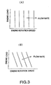
- a step S13 the exhaust gas flow rate is computed according to the map of Fig. 3 based on the engine rotation speed and load.
- Fig. 3(A) shows the characteristics of a natural intake engine
- Fig. 3(B) shows the characteristics of an engine with a turbocharger.
- the differential pressure upstream and downstream of the filter 1 increases as the particulate collection amount increases, but it fluctuates according to the exhaust gas flow rate at that time, and for an identical collection amount, the differential pressure becomes larger the higher the exhaust gas flow rate becomes.
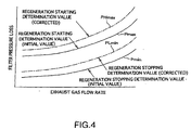
- a regeneration starting determination value which is a pressure value when regeneration starts, and a regeneration stopping value which is a pressure value when regeneration stops, are read from a table as shown in Fig. 4 which sets the regeneration determination values based on the amount of exhaust gas flow rate at that time.
- the regeneration determination value is set as a value equivalent to a pressure value when the particulate collection amount reaches a predetermined value.
- the filter pressure loss at regeneration starting i.e., the upstream/downstream differential pressure
- the differential pressure at regeneration stopping after particulate combustion falls. Therefore, the regeneration determination values are set correspondingly.
- the regeneration starting determination value and regeneration stopping determination value become larger as the exhaust gas flow rate increases.
- the running distance of the vehicle is read from the output of the running distance sensor 8, and in a step S16, based on this running distance, the regeneration starting determination value and regeneration stopping determination value are corrected.
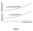
- oil ash generated by combustion of engine oil is contained in the exhaust and this oil ash deposits on the filter 1, the differential pressure upstream and downstream of the filter 1 will increase according to the oil ash deposition amount.
- the oil ash does not burn when the filter is regenerated. For this reason, the oil ash deposition amount increases the longer the engine running time.
- the correction values Kmax, Kmin are both values which increase according to the running distance.
- the regeneration starting determination value and regeneration stopping determination value after this correction are shown by the dot-and-dash line of Fig. 4, and they are both large values compared with the values before correction.
- the amount of oil ash deposited on the filter 1 increases according to the running distance of the vehicle, so the filter 1 gradually becomes clogged and filter pressure loss increases.
- the filter suffers pressure loss due to collected particulates and also due to deposition of oil ash, so by adding the pressure loss due to this oil ash to the pressure value for determining regeneration starting and stopping, determination correction values depending on the particulate collection amount can be precisely computed.
- regeneration control of the filter will be described according to the main routine of Fig. 2(A). This control is performed while reading the execution result of the above-mentioned subroutine.
- a step S1 the magnitudes of the differential pressure P upstream and downstream of the filter 1 and the regeneration starting determination value PHmax are compared, and the regeneration starting time is determined.
- the differential pressure P is larger than the determination value PHmax, it is determined that it is time for the filter to be regenerated, otherwise, the routine returns to its original state.
- the routine proceeds to a step S2 and it is determined whether or not the present running condition satisfies regeneration conditions.
- regeneration conditions such as when the engine is running in the steady state
- the routine shifts to regeneration control in a step S3.
- the system waits for a running state when the regeneration conditions are satisfied.
- the fuel injection timing of the fuel injected from the fuel injector 2 is relatively delayed, or the combustion in the engine is delayed from the regular state by injecting once again after the injection with the usual fuel injection timing, so as to raise the exhaust gas temperature, and the particulates collected by the filter 1 are thereby burned.
- a step S4 the differential pressure P upstream and downstream of the filter 1 is compared with the regeneration stopping determination value PLmin, and regeneration control is continued until the differential pressure P becomes less than the regeneration stopping determination value PLmin.
- the differential pressure upstream and downstream of the filter 1 falls to less than the regeneration stopping determination value PLmin, it is determined that the regeneration stopping time has been reached, and regeneration control is stopped.
- the particulate contained in the exhaust from the engine are collected on the filter 1, and their discharge to the outside atmosphere is prevented. As the particulate collection amount increases, the filter 1 becomes clogged, and the upstream/downstream differential pressure gradually becomes large.
- the determination of the regeneration time is performed based on a comparison of the regeneration starting pressure based on the exhaust gas flow rate at that time, and the upstream/downstream differential pressure (pressure loss) of the filter 1.
- the pressure loss of the filter 1 becomes large the more the particulate (PM) collection amount increases, and this pressure loss increases relatively due to deposition of oil ash, as shown also in Fig. 7.
- PM particulate
- these corrected determination values contain an oil ash deposition fraction, and by comparing this with the pressure loss of the filter 1, a precise determination of regeneration starting time and regeneration stopping time reflecting the actual particulate collection amount can be made.
- Fig. 9 shows the regeneration of the filter 1, and the resulting pressure loss state of the filter 2, when the regeneration determination values have been corrected relative to the oil deposition amount on the filter 1 (dot-and-dash line in the figure), and when the regeneration determination values have not been corrected relative to the oil deposition amount on the filter 1 (dotted line in the figure).
- the determination value (differential pressure) for filter regeneration starting and the determination value for regeneration stopping are low, whereas, the determination values are relatively higher due to correction after oil ash deposition.
- regeneration starting and stopping correspond precisely to the actual particulate collection amount of the filter 1, and for this reason, the regeneration time is effectively set.
- the differential pressure upstream and downstream of the filter 1 rapidly attains the regeneration starting determination value.
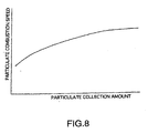
- the particulate collection amount decreases to less than in the steady state.
- the combustion rate varies due to the particulate collection amount, and the combustion rate decreases, the less the collection amount becomes.
- the time required for regeneration increases, and the fuel-cost performance deteriorates by a corresponding amount.That is, if the combustion rate falls, particulates do not burn easily, and it takes time for the differential pressure of the filter 1 to fall to the regeneration stopping determination value.
- the particulate collection amount can be determined correctly, the regeneration time is always accurately, and deterioration of fuel cost-performance is suppressed.
- the oil ash deposition amount was estimated based on the running distance of the vehicle, and the regeneration starting and stopping determination values were corrected accordingly, but in this embodiment, the following processing is performed.
- regeneration is performed when the filter differential pressure reaches a predetermined regeneration starting determination value, and even if regeneration is stopped when it has fallen to the regeneration stopping determination value, the processing time required for regeneration increases by the amount the actual particulate collection amount has decreased, and the temperature difference (outlet temperature - inlet temperature) between the inlet temperature and the outlet temperature of the filter 1 during regeneration becomes small.
- the output of the temperature sensor 4 at the inlet of the filter 1 and the output of the temperature sensor 5 at the outlet of the filter 1 during regeneration are compared, and the regeneration starting and regeneration stopping determination values are corrected using the correction values Kmax, Kmin as shown in Fig. 10.
- the particulates which are actually collected can be increased to a predetermined set amount by increasing the regeneration determination values.
- Fig. 11 shows the characteristics of the exhaust gas temperature at the inlet and outlet of the filter 1 when regeneration is performed. Regeneration starts at a time t0, the exhaust gas temperature at the inlet rises as shown by the solid line during the period t1, and subsequently, a constant temperature is maintained during regeneration. On the other hand, as the particulates collected by the filter 1 burn, the exhaust gas temperature at the outlet shown by the dotted line becomes higher than the temperature at the inlet.
- the temperature rise at the outlet side is slightly slower than the temperature rise at the inlet side, and after it eventually reaches a maximum temperature, the temperature starts to drop.
- the outlet temperature remains higher than the inlet temperature.
- the difference between the inlet temperature and outlet temperature corresponding to the particulate combustion amount may for example be computed as the average temperature difference during the interval t1, computed as a temperature difference of the inlet temperature T1b when the outlet has reached a maximum temperature T2max, or calculated as a temperature difference between an outlet temperature T2a and an inlet temperature T1a at a point (t0 + t1) when a fixed time has elapsed from the start of regeneration.
- a correction based on the temperature difference between the inlet and outlet may be performed instead of the correction of the regeneration starting determination value and regeneration stopping determination value based on the running distance by reading the vehicle running distance, which is performed in the steps S15, S16 of the flowchart of Fig. 2(B).
- the temperature difference at the filter inlet and outlet when regeneration is performed on the immediately preceding occasion is stored, and the regeneration starting and stopping determination values are corrected based thereon.
- the correction values are data obtained when the regeneration processing was performed on the immediately preceding occasion, but this approximates the latest situation and presents no problem in practice.
- the regeneration starting and stopping pressure determination values are respectively corrected so that they are increased.
- the pressure loss correction due to the effect of oil ash deposition is excluded, the regeneration determination values correspond to the particulate collection amount, and regeneration processing is always performed when the predetermined amount of particulates have collected. In this way, the time required for regeneration processing does not needlessly increase, and impairment of fuel cost-performance is suppressed as in the previous embodiment.
- the filter 1 may be a catalyst support type.
- the oil ash deposition amount is estimated depending on the regeneration time of the filter 1, and the regeneration starting determination value and regeneration stopping determination value are respectively corrected thereby.
- the regeneration starting and stopping determination values are respectively corrected to become higher according to the regeneration processing time using the correction values Kmax, Kmin shown in Fig. 12.
- the regeneration processing time is the time required from when regeneration starts to when it is determined that regeneration has stopped. This correction is also performed by the steps S 15, S 16 of the flowchart of Fig. 2(B). In this case, the regeneration starting and stopping determination values are corrected using the correction values based on the regeneration processing time on the immediately preceding occasion. In this way, oil ash deposition is excluded, and the regeneration of the filter 1 corresponds precisely to the particulate collection amount.
- the particulate collection amount for the same pressure loss of the filter 1 decreases compared to the case when oil ash does not deposit.
- the particulate collection amount varies according to the running history of the engine, i.e., the engine rotation speed/load history.
- Fig. 13 shows the particulate discharge amount based on the engine rotation speed and load.
- the particulate collection amount can be estimated.
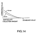
- the regeneration starting and stopping determination values are corrected by the correction values Kmax, Kmin according to the particulate collection amount as shown in Fig. 14.
- the regeneration starting and stopping determination amounts are corrected by correction values related to the particulate collection amount instead of the correction performed in the steps S 15, S16 of the flowchart of Fig. 2.
- the particulate collection amount up to next regeneration can be made to converge to a precise predetermined value.
- the pressure loss of the filter 1 was detected by a differential pressure sensor, but if the pressure fluctuation downstream of the filter is small, the pressure loss may also be estimated by detecting only the upstream exhaust gas pressure. It is also possible to detect both upstream and downstream exhaust gas pressure to estimate the pressure loss of the filter 1.
- the above description primarily provides an engine exhaust purification device for a vehicle engine having a filter which collects particulate in an exhaust passage.
- the device comprises a sensor which detects a differential pressure upstream and downstream of the filter, a sensor which detects an exhaust gas flow rate, a device which raises the exhaust gas temperature upstream of the filter, and a controller which functions to: estimate an oil ash deposition amount on the filter, set a regeneration determination value which performs regeneration of the filter based on the oil ash deposition amount and exhaust gas flow rate, and increase the exhaust gas temperature upstream of the filter to perform regeneration of the filter when it is determined that it is time to regenerate the filter by comparing the detected differential pressure and the regeneration determination value.
Landscapes
- Engineering & Computer Science (AREA)
- Chemical & Material Sciences (AREA)
- Combustion & Propulsion (AREA)
- Mechanical Engineering (AREA)
- General Engineering & Computer Science (AREA)
- Processes For Solid Components From Exhaust (AREA)
- Combined Controls Of Internal Combustion Engines (AREA)
- Electrical Control Of Air Or Fuel Supplied To Internal-Combustion Engine (AREA)
Description
- The present invention relates to an exhaust emission purification device according to the preamble portion of
claim 1. - Such an exhaust emission purification device is known from prior art document US 5,287,698.
- In order to process the exhaust gas particulate discharged from a diesel engine JP-A 7-11935 proposes disposing a filter in an exhaust system.In this case, if the particulate collection amount (mainly carbon particles) in the filter increases, the resistance of the passage will increase and the exhaust gas pressure loss of the engine will increase.
- Thus, when the collection amount of the particulate in the filter reaches a predetermined amount, the filter temperature is raised by a heater to burn the collected particulate and regenerate the filter.The regeneration time is determined based on the exhaust gas differential pressure upstream and downstream of the filter, and when the differential pressure exceeds a set value, it is determined that it is time to regenerate the filter.
- When engine oil burns, oil ash is produced although in very small amount. If the oil ash included in the exhaust gas deposits on the filter, even if not much particulates have actually collected on the filter, the above-mentioned differential pressure will become large. Oil ash cannot be burnt like particulates, and its deposition amount increases gradually with the elapsed running time. For this reason, if deposited oil ash on the filter is ignored, the determination of filter regeneration time will be incorrect.heat energy is required to raise the temperature during filter regeneration, but if unnecessary regeneration operations are repeated, fuel cost-performance will be impaired.
- It is therefore an objective of the present invention to provide an engine exhaust purification device as indicated above being capable of correctly determining the regeneration time of a filter, appropriately performing exhaust gas purification and reducing the loss of fuel cost-performance as far as possible.
- This objective is solved by an engine purification device for a vehicle having the features of
claim 1. - Further preferred embodiments are laid down in the dependent claims.
- In the following, the present invention is explained in greater detail with respect to several embodiments thereof in conjunction with the accompanying drawings, wherein:
-
- Fig. 1 is a schematic block diagram showing one embodiment.
- Fig. 2 is a flowchart describing the control of such an embodiment; Fig. 2(A) is a main routine and Fig. 2(B) is a subroutine.
- Fig. 3 shows the characteristics of exhaust gas flow rate based on engine load and engine rotation speed; Fig. 3(A) is a natural intake engine, and Fig. 3(B) is a turbo charged engine.
- Fig. 4 is a descriptive drawing showing regeneration starting and stopping characteristics.
- Fig. 5 is a diagram showing the characteristics of correction values for regeneration starting and stopping determination values based on running distance.
- Fig. 6 is a diagram showing oil ash deposition amount and filter pressure loss characteristics based on running distance.
- Fig. 7 is a diagram showing particulate collection amount and filter pressure loss characteristics, by comparing an initial state with the state after deposition of oil ash.
- Fig. 8 is a diagram showing filter pressure loss variation characteristics due to a filter regeneration operation.
- Fig. 9 is a diagram showing particulate collection amount and combustion rate characteristics during filter regeneration.
- Fig. 10 is a diagram showing the characteristics of correction values of regeneration starting and stopping determination values based on the filter inlet and outlet temperature.
- Fig. 11 is a diagram showing filter inlet and outlet temperature characteristics due to regeneration.
- Fig. 12 is a diagram showing the characteristics of correction values of regeneration starting and stopping determination values based on regeneration time.
- Fig. 13 is a characteristic diagram showing the particulate discharge amount based on the engine rotation speed and load.
- Fig. 14 is a diagram showing the characteristics of correction values of regeneration starting and stopping determination values based on the particulate collection amount.
-
- An embodiment will now be described referring to the drawings.
- First, in Fig. 1, 20 shows a diesel engine which has an
intake passage 21 and anexhaust passage 22. - A
filter 1 which collects particulates in the exhaust is installed in theexhaust passage 22. - A
controller 30 is provided which regenerates thefilter 1 when the particulate collection amount of thefilter 1 reaches a predetermined value. - The
controller 30 comprises a microprocessor, memory and input/output interface. - A
differential pressure sensor 3 is installed in a differential pressure detection passage which bypasses thefilter 1 in order to detect the exhaust gas differential pressure upstream and downstream of thefilter 1, andtemperature sensors 4, 5 are installed to detect the inlet and outlet temperatures of thefilter 1, respectively. - An engine
rotation speed sensor 6 and engine load sensor 7 are provided to detect the engine exhaust gas flow rate, and a runningdistance sensor 8 is provided to detect the running distance of the vehicle.The outputs of these sensors are sent to thecontroller 30. Based thereon, the particulate collection amount of thefilter 1 is determined and regeneration of thefilter 1 is performed with a predetermined timing, as described later. - The regeneration of the
filter 1 is performed by raising the exhaust gas temperature, by delaying the fuel injection timing of the fuel injected from the fuel injector (for example, common-rail fuel injector) 2 of thediesel engine 20 compared to the fuel injection timing during ordinary running, or by performing an additional injection once after the ordinary injection. - Fig. 2 is a flowchart for performing regeneration in the
controller 30; (A) shows the main routine, (B) shows a subroutine. These are repeatedly performed at a predetermined interval. - The regeneration of the
filter 1 will be described according to this flowchart. - First, the subroutine (B) for correction of the regeneration determination value will be described.
- In a step S11, a differential pressureP upstream and downstream of the

filter 1 is read from the output of thedifferential pressure sensor 3, and in a step S12, the engine rotation speed and load are read from the output of therotation speed sensor 6 and the load sensor 7. - In a step S13, the exhaust gas flow rate is computed according to the map of Fig. 3 based on the engine rotation speed and load.Fig. 3(A) shows the characteristics of a natural intake engine, and Fig. 3(B) shows the characteristics of an engine with a turbocharger.
- The differential pressure upstream and downstream of the
filter 1 increases as the particulate collection amount increases, but it fluctuates according to the exhaust gas flow rate at that time, and for an identical collection amount, the differential pressure becomes larger the higher the exhaust gas flow rate becomes. - In a step S14, a regeneration starting determination value which is a pressure value when regeneration starts, and a regeneration stopping value which is a pressure value when regeneration stops, are read from a table as shown in Fig. 4 which sets the regeneration determination values based on the amount of exhaust gas flow rate at that time.
- The regeneration determination value is set as a value equivalent to a pressure value when the particulate collection amount reaches a predetermined value.
- The filter pressure loss at regeneration starting, i.e., the upstream/downstream differential pressure, is large, and by comparison, the differential pressure at regeneration stopping after particulate combustion falls. Therefore, the regeneration determination values are set correspondingly.
- The regeneration starting determination value and regeneration stopping determination value become larger as the exhaust gas flow rate increases.Next, in a step S15, the running distance of the vehicle is read from the output of the running
distance sensor 8, and in a step S16, based on this running distance, the regeneration starting determination value and regeneration stopping determination value are corrected. - If oil ash generated by combustion of engine oil is contained in the exhaust and this oil ash deposits on the
filter 1, the differential pressure upstream and downstream of thefilter 1 will increase according to the oil ash deposition amount. The oil ash does not burn when the filter is regenerated. For this reason, the oil ash deposition amount increases the longer the engine running time. - Thus, it will be considered that, by correcting the aforesaid determination values according to the oil ash deposition amount using the correction values, Kmax, Kmin set by a table as shown in Fig. 5, these corrected determination values depend on the actual particulate collection amount collected in the
filter 1. A regeneration starting determination value PHmax is calculated as a basic value (initial value) Pmax+ correction value Kmax, and the regeneration stopping determination value PLmin is likewise calculated as a basic value (initial value) Pmin+Kmin. However, it is also possible to compute the regeneration determination values by multiplying the basic values by correction values. - As the oil ash deposition amount increases according to the running distance of the vehicle, the correction values Kmax, Kmin are both values which increase according to the running distance. The regeneration starting determination value and regeneration stopping determination value after this correction are shown by the dot-and-dash line of Fig. 4, and they are both large values compared with the values before correction.
- As shown in Fig. 6, the amount of oil ash deposited on the
filter 1 increases according to the running distance of the vehicle, so thefilter 1 gradually becomes clogged and filter pressure loss increases. - Thus, the filter suffers pressure loss due to collected particulates and also due to deposition of oil ash, so by adding the pressure loss due to this oil ash to the pressure value for determining regeneration starting and stopping, determination correction values depending on the particulate collection amount can be precisely computed.
- Next, regeneration control of the filter will be described according to the main routine of Fig. 2(A). This control is performed while reading the execution result of the above-mentioned subroutine.
- In a step S1, the magnitudes of the differential pressure
filter 1 and the regeneration starting determination value PHmax are compared, and the regeneration starting time is determined. When the differential pressure - When the pressure loss of the
filter 1 increases and it is determined that regeneration has started, the routine proceeds to a step S2 and it is determined whether or not the present running condition satisfies regeneration conditions. When regeneration conditions are satisfied, such as when the engine is running in the steady state, the routine shifts to regeneration control in a step S3. When the regeneration conditions are not satisfied, the system waits for a running state when the regeneration conditions are satisfied. - In the regeneration control of the step S3, the fuel injection timing of the fuel injected from the fuel injector 2 is relatively delayed, or the combustion in the engine is delayed from the regular state by injecting once again after the injection with the usual fuel injection timing, so as to raise the exhaust gas temperature, and the particulates collected by the
filter 1 are thereby burned. - In a step S4, the differential pressure
filter 1 is compared with the regeneration stopping determination value PLmin, and regeneration control is continued until the differential pressurefilter 1 falls to less than the regeneration stopping determination value PLmin, it is determined that the regeneration stopping time has been reached, and regeneration control is stopped. - Next, the overall operation will be described referring to Fig. 7-Fig. 9.
- The particulate contained in the exhaust from the engine are collected on the
filter 1, and their discharge to the outside atmosphere is prevented. As the particulate collection amount increases, thefilter 1 becomes clogged, and the upstream/downstream differential pressure gradually becomes large. - When the differential pressure becomes large, exhaust gas pressure loss will increase and the performance of the engine will be impaired. Hence, when the collected particulates exceed a predetermined amount, regeneration of the
filter 1 is performed. - The determination of the regeneration time is performed based on a comparison of the regeneration starting pressure based on the exhaust gas flow rate at that time, and the upstream/downstream differential pressure (pressure loss) of the
filter 1. - The pressure loss of the
filter 1 becomes large the more the particulate (PM) collection amount increases, and this pressure loss increases relatively due to deposition of oil ash, as shown also in Fig. 7. Initially, when the vehicle running distance is small, there is little deposition of oil ash, but when the running distance increases, the oil ash deposition amount will increase. Hence, the amount of oil ash deposited on thefilter 1 is estimated according to the running distance, and the regeneration starting determination value and stopping determination value are corrected based on this estimate. - Therefore, these corrected determination values contain an oil ash deposition fraction, and by comparing this with the pressure loss of the
filter 1, a precise determination of regeneration starting time and regeneration stopping time reflecting the actual particulate collection amount can be made. - Fig. 9 shows the regeneration of the
filter 1, and the resulting pressure loss state of the filter 2, when the regeneration determination values have been corrected relative to the oil deposition amount on the filter 1 (dot-and-dash line in the figure), and when the regeneration determination values have not been corrected relative to the oil deposition amount on the filter 1 (dotted line in the figure). - As seen from this figure, in the filter initial state shown by the solid line in the figure, the determination value (differential pressure) for filter regeneration starting and the determination value for regeneration stopping are low, whereas, the determination values are relatively higher due to correction after oil ash deposition.
- Therefore, regeneration starting and stopping correspond precisely to the actual particulate collection amount of the
filter 1, and for this reason, the regeneration time is effectively set.On the other hand, if correction is not performed despite the deposition of oil ash, even if the actual particulate amount does not reach the amount at which regeneration is necessary, as there is a pressure loss due to the deposition of oil ash, the differential pressure upstream and downstream of thefilter 1 rapidly attains the regeneration starting determination value. - In this case, the particulate collection amount decreases to less than in the steady state. As shown in Fig. 8, the combustion rate varies due to the particulate collection amount, and the combustion rate decreases, the less the collection amount becomes. Hence, the time required for regeneration increases, and the fuel-cost performance deteriorates by a corresponding amount.That is, if the combustion rate falls, particulates do not burn easily, and it takes time for the differential pressure of the
filter 1 to fall to the regeneration stopping determination value. - However, according to the teaching of the present embodiments, by estimating the oil ash deposition amount and applying a correction, the particulate collection amount can be determined correctly, the regeneration time is always accurately, and deterioration of fuel cost-performance is suppressed.
- Next, another embodiment will be described. In this embodiment, the technique of estimating the oil ash deposition amount of the
filter 1 is different. - In the preceding embodiment, the oil ash deposition amount was estimated based on the running distance of the vehicle, and the regeneration starting and stopping determination values were corrected accordingly, but in this embodiment, the following processing is performed.
- When the oil ash deposition amount increases, the particulate collection amount when the differential pressure upstream and downstream of the
filter 1 is the same will relatively decrease. - In this case, regeneration is performed when the filter differential pressure reaches a predetermined regeneration starting determination value, and even if regeneration is stopped when it has fallen to the regeneration stopping determination value, the processing time required for regeneration increases by the amount the actual particulate collection amount has decreased, and the temperature difference (outlet temperature - inlet temperature) between the inlet temperature and the outlet temperature of the
filter 1 during regeneration becomes small. Thus, the output of the temperature sensor 4 at the inlet of thefilter 1 and the output of thetemperature sensor 5 at the outlet of thefilter 1 during regeneration are compared, and the regeneration starting and regeneration stopping determination values are corrected using the correction values Kmax, Kmin as shown in Fig. 10. - Even if the differential pressure of the
filter 1 is the same, the actual particulate collection amount decreases, i.e., the oil ash deposition amount increases, the less the temperature difference between the inlet temperature and outlet temperature of thefilter 1. Therefore, the regeneration starting and regeneration stopping determination values are both corrected so that they are higher. - Even if the oil ash deposition amount increases with time, the particulates which are actually collected can be increased to a predetermined set amount by increasing the regeneration determination values.
- Fig. 11 shows the characteristics of the exhaust gas temperature at the inlet and outlet of the
filter 1 when regeneration is performed. Regeneration starts at a time t0, the exhaust gas temperature at the inlet rises as shown by the solid line during the periodfilter 1 burn, the exhaust gas temperature at the outlet shown by the dotted line becomes higher than the temperature at the inlet. - The temperature rise at the outlet side is slightly slower than the temperature rise at the inlet side, and after it eventually reaches a maximum temperature, the temperature starts to drop. During regeneration when the particulates are burning, the outlet temperature remains higher than the inlet temperature.
- The difference between the inlet temperature and outlet temperature corresponding to the particulate combustion amount may for example be computed as the average temperature difference during the interval
- A correction based on the temperature difference between the inlet and outlet may be performed instead of the correction of the regeneration starting determination value and regeneration stopping determination value based on the running distance by reading the vehicle running distance, which is performed in the steps S15, S16 of the flowchart of Fig. 2(B). The temperature difference at the filter inlet and outlet when regeneration is performed on the immediately preceding occasion is stored, and the regeneration starting and stopping determination values are corrected based thereon. The correction values are data obtained when the regeneration processing was performed on the immediately preceding occasion, but this approximates the latest situation and presents no problem in practice.
- When the temperature difference at the filter inlet and outlet becomes small, the regeneration starting and stopping pressure determination values are respectively corrected so that they are increased. As a result, the pressure loss correction due to the effect of oil ash deposition is excluded, the regeneration determination values correspond to the particulate collection amount, and regeneration processing is always performed when the predetermined amount of particulates have collected. In this way, the time required for regeneration processing does not needlessly increase, and impairment of fuel cost-performance is suppressed as in the previous embodiment.
- In this case, the
filter 1 may be a catalyst support type. - Describing now a further embodiment, the oil ash deposition amount is estimated depending on the regeneration time of the
filter 1, and the regeneration starting determination value and regeneration stopping determination value are respectively corrected thereby. - When the oil ash deposition amount increases, the particulate collection amount when the differential pressure of the filter reaches the regeneration starting determination value relatively decreases, the particulate combustion rate decreases and the processing time required for regeneration becomes longer. Hence, the regeneration starting and stopping determination values are respectively corrected to become higher according to the regeneration processing time using the correction values Kmax, Kmin shown in Fig. 12.
- The regeneration processing time is the time required from when regeneration starts to when it is determined that regeneration has stopped. This correction is also performed by the steps S 15,
S 16 of the flowchart of Fig. 2(B). In this case, the regeneration starting and stopping determination values are corrected using the correction values based on the regeneration processing time on the immediately preceding occasion. In this way, oil ash deposition is excluded, and the regeneration of thefilter 1 corresponds precisely to the particulate collection amount. - Describing now yet another embodiment, when the oil ash deposition amount increases, the particulate collection amount for the same differential pressure of the
filter 1 decreases, so the particulate collection amount until regeneration processing is predicted from the running history to predict the regeneration starting and stopping determination values. - When the oil ash deposition amount increases, the particulate collection amount for the same pressure loss of the
filter 1 decreases compared to the case when oil ash does not deposit. The particulate collection amount varies according to the running history of the engine, i.e., the engine rotation speed/load history. Fig. 13 shows the particulate discharge amount based on the engine rotation speed and load. - Therefore, by calculating the integral value of the particulate discharge amount per unit time until the next regeneration processing, the particulate collection amount can be estimated.
- When the differential pressure reaches the regeneration determination value, if the particulate collection amount calculated from the running history is small, it means that the oil ash deposition amount is large. Hence, the regeneration starting and stopping determination values are corrected by the correction values Kmax, Kmin according to the particulate collection amount as shown in Fig. 14. In this case also, the regeneration starting and stopping determination amounts are corrected by correction values related to the particulate collection amount instead of the correction performed in the steps S 15, S16 of the flowchart of Fig. 2.
- As a result, by increasing the regeneration determination values the more the particulate collection amount decreases and the higher the estimated value of the oil ash deposition amount, the particulate collection amount up to next regeneration can be made to converge to a precise predetermined value.
- In the above description, the pressure loss of the
filter 1 was detected by a differential pressure sensor, but if the pressure fluctuation downstream of the filter is small, the pressure loss may also be estimated by detecting only the upstream exhaust gas pressure. It is also possible to detect both upstream and downstream exhaust gas pressure to estimate the pressure loss of thefilter 1. - The above description primarily provides an engine exhaust purification device for a vehicle engine having a filter which collects particulate in an exhaust passage. The device comprises a sensor which detects a differential pressure upstream and downstream of the filter, a sensor which detects an exhaust gas flow rate, a device which raises the exhaust gas temperature upstream of the filter, and a controller which functions to: estimate an oil ash deposition amount on the filter, set a regeneration determination value which performs regeneration of the filter based on the oil ash deposition amount and exhaust gas flow rate, and increase the exhaust gas temperature upstream of the filter to perform regeneration of the filter when it is determined that it is time to regenerate the filter by comparing the detected differential pressure and the regeneration determination value.
Claims (13)
- Engine exhaust purification device for a vehicle having a filter (1) collecting particulates in an exhaust passage (22) comprising:characterized In thata sensor (3) for detecting a differential pressure (ΔP) upstream and downstream of the filter (1), a device for raising an exhaust gas temperature (T1a) upstream of the filter (1), and a controller (30) adapted to estimate an oil ash deposition amount on the filter (1) and to increase the exhaust gas temperature (T1a) upstream of the filter (1) to perform a regeneration of the filter (1),
the controller (30) is further adapted to determine an exhaust gas flow rate in conjunction with a sensor arrangement (6,7), and to compute a corrected pressure value (PHmax) determining the start of the filter regeneration based on the oil ash deposition amount and the exhaust gas flow rate, wherein it is determined that it is time to regenerate the filter (1) by comparing the detected differential pressure (ΔP) with the corrected pressure value (PHmax) determining the start of the filter regeneration. - Engine exhaust purification device according to claim 1, characterized by a regeneration determination value comprising a regeneration starting determination value (PHmax) and a regeneration stopping determination value (PLmin), wherein the controller is adapted to start regeneration when the differential pressure (ΔP) reaches the regeneration starting determination value (PHmax), and to stop regeneration when the differential pressure (ΔP) decreases to the regeneration stopping determination value (PLmin).
- Engine exhaust purification device according to claim 2, characterized in that the regeneration determination value is set to increase the larger the exhaust flow rate becomes.
- Engine exhaust purification device according to one of the preceding claims 1 to 3, characterized in that the exhaust gas flow rate is estimated based on an engine rotation speed and an engine load.
- Engine exhaust purification device according to at least one of the claims 2 to 4, characterized in that the regeneration determination value is set to increase the larger the oil ash deposition amount becomes.
- Engine exhaust purification device according to at least one of the preceding claims 1 to 5, characterized in that the oil ash deposition amount is estimated based on the vehicle running distance.
- Engine exhaust purification device according to at least one of the preceding claims 1 to 5, characterized in that the oil ash deposition amount is estimated based on the engine running history.
- Engine exhaust purification device according to claim 7, characterized in that the engine running history is estimated based on the engine rotation speed and load history.
- Engine exhaust purification device according to at least one of the preceding claims 1 to 5 characterized by further sensors adapted to detect an exhaust gas temperature upstream and downstream of the filter (4,5), wherein the oil ash deposition amount is estimated based on the upstream and downstream exhaust gas temperature.
- Engine exhaust purification device according to at least one of the preceding claims 1 to 5, characterized by means for measuring a regeneration processing time of the filter, wherein the oil ash deposition amount is estimated based on the filter regeneration processing time.
- Engine exhaust purification device according to at least one of the preceding claims 1 to 10, characterized by an exhaust gas temperature raise device adapted to increase the exhaust gas temperature by delaying a fuel injection timing to the engine compared to a fuel injection timing in the normal running state.
- Engine exhaust purification device according to at least one of the preceding claims 1 to 10, characterized by an exhaust gas temperature raise device adapted to increase the exhaust gas temperature by repeating fuel injection after performing a fuel injection to the engine in the normal running state.
- Engine exhaust purification device according to at least one of the preceding claims 1 to 12, characterized in that the differential pressures sensor (3) comprises a pressure sensor disposed upstream of the filter, and the differential pressure is estimated based on the output of this pressure sensor.
Applications Claiming Priority (4)
| Application Number | Priority Date | Filing Date | Title |
|---|---|---|---|
| JP2001028238 | 2001-02-05 | ||
| JP2001028238 | 2001-02-05 | ||
| JP2002004427A JP3846309B2 (en) | 2001-02-05 | 2002-01-11 | Exhaust purification device |
| JP2002004427 | 2002-01-11 |
Publications (2)
| Publication Number | Publication Date |
|---|---|
| EP1229223A1 EP1229223A1 (en) | 2002-08-07 |
| EP1229223B1 true EP1229223B1 (en) | 2004-04-21 |
Family
ID=26608918
Family Applications (1)
| Application Number | Title | Priority Date | Filing Date |
|---|---|---|---|
| EP02002551A Expired - Lifetime EP1229223B1 (en) | 2001-02-05 | 2002-02-04 | Engine exhaust emission purification device |
Country Status (3)
| Country | Link |
|---|---|
| EP (1) | EP1229223B1 (en) |
| JP (1) | JP3846309B2 (en) |
| DE (1) | DE60200383T2 (en) |
Cited By (1)
| Publication number | Priority date | Publication date | Assignee | Title |
|---|---|---|---|---|
| US7841171B2 (en) | 2005-11-09 | 2010-11-30 | Denso Corporation | Exhaust emission control device for internal combustion engine |
Families Citing this family (44)
| Publication number | Priority date | Publication date | Assignee | Title |
|---|---|---|---|---|
| US6622480B2 (en) * | 2001-02-21 | 2003-09-23 | Isuzu Motors Limited | Diesel particulate filter unit and regeneration control method of the same |
| DE10234791A1 (en) * | 2002-07-31 | 2004-02-19 | Deutz Ag | Ash load determination for particle filters |
| US7357822B2 (en) * | 2002-08-13 | 2008-04-15 | Bosch Automotive Systems Corporation | Filter control apparatus |
| US7497078B2 (en) | 2002-10-16 | 2009-03-03 | Mitsubishi Fuso Truck And Bus Corporation | Exhaust emission control device of internal combustion engine |
| JP3801135B2 (en) * | 2003-01-08 | 2006-07-26 | 日産自動車株式会社 | Engine exhaust gas purification device |
| JP3864910B2 (en) * | 2003-01-10 | 2007-01-10 | 日産自動車株式会社 | Exhaust gas purification device for internal combustion engine |
| FR2853009B1 (en) * | 2003-03-28 | 2007-07-13 | Renault Sa | METHOD FOR REGENERATING A PARTICLE FILTER AND DEVICE FOR IMPLEMENTING SUCH A METHOD |
| JP4048993B2 (en) * | 2003-04-08 | 2008-02-20 | 日産自動車株式会社 | Engine exhaust purification system |
| US7031827B2 (en) * | 2003-04-11 | 2006-04-18 | Ford Global Technologies, Llc | Computer algorithm to estimate particulate filter regeneration rates |
| DE10325183B4 (en) * | 2003-06-04 | 2013-01-31 | Robert Bosch Gmbh | Method and device for carrying out a method for determining the loading state of a arranged in an exhaust region of an internal combustion engine component |
| FR2862086B1 (en) * | 2003-11-07 | 2006-02-17 | Peugeot Citroen Automobiles Sa | SYSTEM FOR AIDING THE MAINTENANCE OF A PARTICULATE FILTER INTEGRATED IN AN EXHAUST LINE OF A MOTOR VEHICLE ENGINE |
| JP4103813B2 (en) * | 2004-02-02 | 2008-06-18 | トヨタ自動車株式会社 | Exhaust gas purification device for internal combustion engine |
| JP4125255B2 (en) * | 2004-03-11 | 2008-07-30 | トヨタ自動車株式会社 | Exhaust gas purification device for internal combustion engine |
| JP4218556B2 (en) | 2004-03-11 | 2009-02-04 | トヨタ自動車株式会社 | Particulate matter regeneration control device for internal combustion engine exhaust purification device |
| JP4044908B2 (en) | 2004-03-11 | 2008-02-06 | トヨタ自動車株式会社 | Exhaust gas purification device for internal combustion engine |
| JP4052268B2 (en) * | 2004-03-11 | 2008-02-27 | トヨタ自動車株式会社 | Exhaust gas purification device for internal combustion engine |
| JP4161932B2 (en) * | 2004-04-09 | 2008-10-08 | いすゞ自動車株式会社 | Exhaust gas purification system control method and exhaust gas purification system |
| FR2869639B1 (en) * | 2004-04-29 | 2009-06-12 | Peugeot Citroen Automobiles Sa | METHOD FOR DETERMINING THE LOAD OF A TRAP FOR POLLUTANT SUBSTANCES |
| JP4504753B2 (en) * | 2004-07-16 | 2010-07-14 | トヨタ自動車株式会社 | Exhaust gas purification device for internal combustion engine |
| EP1632667A1 (en) * | 2004-09-07 | 2006-03-08 | Renault s.a.s. | Method of regeneration of a particle filter and apparatus for implementing such a method |
| DE102004055605B4 (en) * | 2004-11-18 | 2015-10-29 | Volkswagen Ag | Method for determining soot loading of a particulate filter |
| FR2879244B1 (en) * | 2004-12-14 | 2007-03-16 | Renault Sas | DEVICE FOR CONTROLLING THE REGENERATION OF A PARTICLE FILTER FOR AN INTERNAL COMBUSTION ENGINE AND CORRESPONDING METHOD. |
| JP4574395B2 (en) * | 2005-02-28 | 2010-11-04 | ヤンマー株式会社 | Exhaust gas purification device having particulate filter regeneration function, internal combustion engine equipped with the exhaust gas purification device, and particulate filter regeneration method |
| EP1865165B1 (en) * | 2005-05-13 | 2008-12-10 | HONDA MOTOR CO., Ltd. | Exhaust emission control system for internal combustion engine and control method therefor |
| US7607295B2 (en) * | 2005-07-07 | 2009-10-27 | Nissan Motor Co., Ltd. | Particulate accumulation amount estimating system |
| JP4534969B2 (en) * | 2005-11-25 | 2010-09-01 | 株式会社デンソー | Exhaust purification device for internal combustion engine |
| JP4811024B2 (en) * | 2006-01-05 | 2011-11-09 | 日産自動車株式会社 | Exhaust gas purification filter regeneration start timing control device and regeneration start timing control method |
| JP4692376B2 (en) * | 2006-05-10 | 2011-06-01 | トヨタ自動車株式会社 | Exhaust gas purification device for internal combustion engine |
| JP4863111B2 (en) * | 2006-08-31 | 2012-01-25 | 株式会社デンソー | Exhaust purification device |
| JP4702557B2 (en) * | 2006-08-31 | 2011-06-15 | 三菱自動車工業株式会社 | Exhaust purification device |
| WO2008036010A1 (en) * | 2006-09-19 | 2008-03-27 | Industriell Plåtproduktion Ab | Exhaust gas system |
| FR2908822A1 (en) * | 2006-11-17 | 2008-05-23 | Saint Gobain Ct Recherches | METHOD OF CALIBRATING AND MANAGING AN EXHAUST LINE COMPRISING A PARTICLE FILTER |
| JP5123686B2 (en) * | 2008-02-08 | 2013-01-23 | 三菱重工業株式会社 | DPF accumulation amount estimation device |
| JP4883104B2 (en) * | 2009-02-09 | 2012-02-22 | トヨタ自動車株式会社 | Exhaust gas purification device for internal combustion engine |
| FR2942848B1 (en) * | 2009-03-06 | 2011-03-18 | Peugeot Citroen Automobiles Sa | METHOD FOR ADAPTING A REGENERATION STRATEGY OF A PARTICLE FILTER |
| FR2965013B1 (en) * | 2010-09-22 | 2012-08-31 | Renault Sa | METHOD OF ADAPTIVE ESTIMATING OF A CURRENT LOAD IN SUIEUR OF A PARTICLE FILTER |
| JP5931328B2 (en) * | 2010-09-28 | 2016-06-08 | 三菱重工業株式会社 | Engine exhaust gas purification device and purification method |
| JP5263307B2 (en) * | 2011-01-13 | 2013-08-14 | 日産自動車株式会社 | Exhaust gas purification filter regeneration start timing control device and regeneration start timing control method |
| FR2976319A1 (en) * | 2011-06-10 | 2012-12-14 | Peugeot Citroen Automobiles Sa | METHOD FOR MANAGING THE REGENERATION OF A PARTICLE FILTER |
| US9587574B2 (en) * | 2014-11-26 | 2017-03-07 | Electro-Motive Diesel, Inc. | Exhaust system using ash-compensating regeneration management |
| JP6233450B2 (en) | 2015-06-02 | 2017-11-22 | トヨタ自動車株式会社 | Control device for exhaust purification system |
| JP6146447B2 (en) * | 2015-09-15 | 2017-06-14 | 株式会社豊田自動織機 | Exhaust purification device |
| JP7211193B2 (en) * | 2019-03-25 | 2023-01-24 | 三菱自動車工業株式会社 | Exhaust purification device |
| CN113356985B (en) * | 2021-06-02 | 2022-06-03 | 重庆长安汽车股份有限公司 | Regeneration control method, device and system for particle catcher and vehicle |
Family Cites Families (7)
| Publication number | Priority date | Publication date | Assignee | Title |
|---|---|---|---|---|
| GB2239407B (en) * | 1989-12-27 | 1994-10-12 | Nissan Motor | Exhaust gas purifying device for an internal combustion engine |
| JPH07310524A (en) * | 1994-05-13 | 1995-11-28 | Nippondenso Co Ltd | Diesel particulate collection amount detector |
| IT1266889B1 (en) * | 1994-07-22 | 1997-01-21 | Fiat Ricerche | METHOD OF SELF-PRIMING REGENERATION IN A PARTICULAR FILTER FOR A DIESEL ENGINE WITH COMMON MANIFOLD INJECTION SYSTEM. |
| JP3775021B2 (en) * | 1997-11-20 | 2006-05-17 | 日産自動車株式会社 | Engine exhaust particle processing equipment |
| FR2774421B1 (en) * | 1998-02-02 | 2000-04-21 | Peugeot | SYSTEM FOR MANAGING THE OPERATION OF A PARTICLE FILTER ASSOCIATED WITH A DIESEL ENGINE IN PARTICULAR OF A MOTOR VEHICLE |
| DE60002652T2 (en) * | 1999-11-26 | 2004-04-01 | Renault S.A.S. | Control method of a particle filter and control method of an internal combustion engine |
| FR2804169B1 (en) * | 2000-01-20 | 2002-04-12 | Peugeot Citroen Automobiles Sa | SYSTEM FOR AIDING THE REGENERATION OF A PARTICLE FILTER INTEGRATED IN AN EXHAUST LINE OF A DIESEL ENGINE OF A MOTOR VEHICLE |
-
2002
- 2002-01-11 JP JP2002004427A patent/JP3846309B2/en not_active Expired - Lifetime
- 2002-02-04 DE DE60200383T patent/DE60200383T2/en not_active Expired - Lifetime
- 2002-02-04 EP EP02002551A patent/EP1229223B1/en not_active Expired - Lifetime
Cited By (1)
| Publication number | Priority date | Publication date | Assignee | Title |
|---|---|---|---|---|
| US7841171B2 (en) | 2005-11-09 | 2010-11-30 | Denso Corporation | Exhaust emission control device for internal combustion engine |
Also Published As
| Publication number | Publication date |
|---|---|
| DE60200383T2 (en) | 2004-08-26 |
| DE60200383D1 (en) | 2004-05-27 |
| JP2002303123A (en) | 2002-10-18 |
| JP3846309B2 (en) | 2006-11-15 |
| EP1229223A1 (en) | 2002-08-07 |
Similar Documents
| Publication | Publication Date | Title |
|---|---|---|
| EP1229223B1 (en) | Engine exhaust emission purification device | |
| JP4513593B2 (en) | Exhaust gas purification device for internal combustion engine | |
| EP1431531B1 (en) | Particulate filter regenerating device | |
| EP1455070B1 (en) | Regeneration of particulate filter | |
| JP3969196B2 (en) | Fuel injection control device for internal combustion engine | |
| US7219493B2 (en) | Filter regeneration in engine exhaust gas purification device | |
| EP2218884A1 (en) | Exhaust gas post-processing device | |
| US7146805B2 (en) | Regeneration control of diesel particulate filter | |
| EP1455060B1 (en) | Engine exhaust gas purification device | |
| JP2004197584A (en) | Regeneration device for particulate filter and exhaust gas purification device for engine | |
| EP1741907B1 (en) | Diesel engine exhaust gas after-treatment device | |
| EP1517012A2 (en) | Filter regeneration control | |
| EP1723322B1 (en) | Regeneration controller for exhaust purification apparatus of internal combustion engine | |
| KR101353648B1 (en) | Exhaust gas purification device for internal combustion engine | |
| US7322185B2 (en) | Removal of front end blockage of a diesel particulate filter | |
| EP1464817B1 (en) | Exhaust gas processing device and method for diesel engine | |
| US20050055999A1 (en) | Diesel engine comprising DPM filter and method of estimating amount of DPM trapped in DPM filter | |
| JP2004197722A (en) | Regeneration device for particulate filter and exhaust gas purification device for engine | |
| JP2008232073A (en) | Exhaust emission purifier | |
| JP4185882B2 (en) | Exhaust purification device | |
| JP4635582B2 (en) | Exhaust purification device | |
| JP4333230B2 (en) | Exhaust gas purification system for internal combustion engine | |
| JP4365724B2 (en) | Exhaust purification equipment | |
| JP2003129835A (en) | Exhaust gas purification device | |
| CN100577994C (en) | Internal combustion engine fuel injection control device |
Legal Events
| Date | Code | Title | Description |
|---|---|---|---|
| PUAI | Public reference made under article 153(3) epc to a published international application that has entered the european phase |
Free format text: ORIGINAL CODE: 0009012 |
|
| 17P | Request for examination filed |
Effective date: 20020204 |
|
| AK | Designated contracting states |
Kind code of ref document: A1 Designated state(s): AT BE CH CY DE DK ES FI FR GB GR IE IT LI LU MC NL PT SE TR |
|
| AX | Request for extension of the european patent |
Free format text: AL;LT;LV;MK;RO;SI |
|
| 17Q | First examination report despatched |
Effective date: 20030109 |
|
| AKX | Designation fees paid |
Designated state(s): DE FR GB |
|
| GRAP | Despatch of communication of intention to grant a patent |
Free format text: ORIGINAL CODE: EPIDOSNIGR1 |
|
| GRAS | Grant fee paid |
Free format text: ORIGINAL CODE: EPIDOSNIGR3 |
|
| GRAA | (expected) grant |
Free format text: ORIGINAL CODE: 0009210 |
|
| AK | Designated contracting states |
Kind code of ref document: B1 Designated state(s): DE FR GB |
|
| REG | Reference to a national code |
Ref country code: GB Ref legal event code: FG4D |
|
| REG | Reference to a national code |
Ref country code: IE Ref legal event code: FG4D |
|
| REF | Corresponds to: |
Ref document number: 60200383 Country of ref document: DE Date of ref document: 20040527 Kind code of ref document: P |
|
| ET | Fr: translation filed | ||
| PLBE | No opposition filed within time limit |
Free format text: ORIGINAL CODE: 0009261 |
|
| STAA | Information on the status of an ep patent application or granted ep patent |
Free format text: STATUS: NO OPPOSITION FILED WITHIN TIME LIMIT |
|
| 26N | No opposition filed |
Effective date: 20050124 |
|
| REG | Reference to a national code |
Ref country code: FR Ref legal event code: PLFP Year of fee payment: 15 |
|
| REG | Reference to a national code |
Ref country code: FR Ref legal event code: PLFP Year of fee payment: 16 |
|
| REG | Reference to a national code |
Ref country code: FR Ref legal event code: PLFP Year of fee payment: 17 |
|
| PGFP | Annual fee paid to national office [announced via postgrant information from national office to epo] |
Ref country code: FR Payment date: 20201210 Year of fee payment: 20 |
|
| PGFP | Annual fee paid to national office [announced via postgrant information from national office to epo] |
Ref country code: DE Payment date: 20210119 Year of fee payment: 20 Ref country code: GB Payment date: 20210127 Year of fee payment: 20 |
|
| REG | Reference to a national code |
Ref country code: GB Ref legal event code: PE20 Expiry date: 20220203 |
|
| PG25 | Lapsed in a contracting state [announced via postgrant information from national office to epo] |
Ref country code: GB Free format text: LAPSE BECAUSE OF EXPIRATION OF PROTECTION Effective date: 20220203 |