JP4504753B2 - Exhaust gas purification device for internal combustion engine - Google Patents
Exhaust gas purification device for internal combustion engine Download PDFInfo
- Publication number
- JP4504753B2 JP4504753B2 JP2004210439A JP2004210439A JP4504753B2 JP 4504753 B2 JP4504753 B2 JP 4504753B2 JP 2004210439 A JP2004210439 A JP 2004210439A JP 2004210439 A JP2004210439 A JP 2004210439A JP 4504753 B2 JP4504753 B2 JP 4504753B2
- Authority
- JP
- Japan
- Prior art keywords
- fuel
- amount
- internal combustion
- combustion engine
- filter
- Prior art date
- Legal status (The legal status is an assumption and is not a legal conclusion. Google has not performed a legal analysis and makes no representation as to the accuracy of the status listed.)
- Expired - Fee Related
Links
Images

Classifications
-
- F—MECHANICAL ENGINEERING; LIGHTING; HEATING; WEAPONS; BLASTING
- F02—COMBUSTION ENGINES; HOT-GAS OR COMBUSTION-PRODUCT ENGINE PLANTS
- F02D—CONTROLLING COMBUSTION ENGINES
- F02D41/00—Electrical control of supply of combustible mixture or its constituents
- F02D41/02—Circuit arrangements for generating control signals
- F02D41/021—Introducing corrections for particular conditions exterior to the engine
- F02D41/0235—Introducing corrections for particular conditions exterior to the engine in relation with the state of the exhaust gas treating apparatus
- F02D41/027—Introducing corrections for particular conditions exterior to the engine in relation with the state of the exhaust gas treating apparatus to purge or regenerate the exhaust gas treating apparatus
- F02D41/029—Introducing corrections for particular conditions exterior to the engine in relation with the state of the exhaust gas treating apparatus to purge or regenerate the exhaust gas treating apparatus the exhaust gas treating apparatus being a particulate filter
-
- F—MECHANICAL ENGINEERING; LIGHTING; HEATING; WEAPONS; BLASTING
- F02—COMBUSTION ENGINES; HOT-GAS OR COMBUSTION-PRODUCT ENGINE PLANTS
- F02D—CONTROLLING COMBUSTION ENGINES
- F02D41/00—Electrical control of supply of combustible mixture or its constituents
- F02D41/30—Controlling fuel injection
- F02D41/38—Controlling fuel injection of the high pressure type
- F02D41/40—Controlling fuel injection of the high pressure type with means for controlling injection timing or duration
- F02D41/402—Multiple injections
- F02D41/405—Multiple injections with post injections
-
- F—MECHANICAL ENGINEERING; LIGHTING; HEATING; WEAPONS; BLASTING
- F02—COMBUSTION ENGINES; HOT-GAS OR COMBUSTION-PRODUCT ENGINE PLANTS
- F02D—CONTROLLING COMBUSTION ENGINES
- F02D2250/00—Engine control related to specific problems or objectives
- F02D2250/11—Oil dilution, i.e. prevention thereof or special controls according thereto
-
- F—MECHANICAL ENGINEERING; LIGHTING; HEATING; WEAPONS; BLASTING
- F02—COMBUSTION ENGINES; HOT-GAS OR COMBUSTION-PRODUCT ENGINE PLANTS
- F02D—CONTROLLING COMBUSTION ENGINES
- F02D41/00—Electrical control of supply of combustible mixture or its constituents
- F02D41/02—Circuit arrangements for generating control signals
- F02D41/04—Introducing corrections for particular operating conditions
- F02D41/047—Taking into account fuel evaporation or wall wetting
-
- Y—GENERAL TAGGING OF NEW TECHNOLOGICAL DEVELOPMENTS; GENERAL TAGGING OF CROSS-SECTIONAL TECHNOLOGIES SPANNING OVER SEVERAL SECTIONS OF THE IPC; TECHNICAL SUBJECTS COVERED BY FORMER USPC CROSS-REFERENCE ART COLLECTIONS [XRACs] AND DIGESTS
- Y02—TECHNOLOGIES OR APPLICATIONS FOR MITIGATION OR ADAPTATION AGAINST CLIMATE CHANGE
- Y02T—CLIMATE CHANGE MITIGATION TECHNOLOGIES RELATED TO TRANSPORTATION
- Y02T10/00—Road transport of goods or passengers
- Y02T10/10—Internal combustion engine [ICE] based vehicles
- Y02T10/40—Engine management systems
Description
本発明は、内燃機関の排気浄化装置に関し、特に、内燃機関の排気通路に設けられ排気中の粒子状物質を捕集するパティキュレートフィルタを備えた内燃機関の排気浄化装置に関する。 The present invention relates to an exhaust gas purification apparatus for an internal combustion engine, and more particularly to an exhaust gas purification apparatus for an internal combustion engine provided with a particulate filter that is provided in an exhaust passage of the internal combustion engine and collects particulate matter in the exhaust gas.
内燃機関の排気浄化装置においては、排気通路に設けられた触媒の排気浄化能力を再生すべく該触媒を昇温させるために、気筒内で主燃料噴射の後に副燃料噴射を行うことによって該触媒に燃料を供給する場合がある。 In an exhaust gas purification apparatus for an internal combustion engine, in order to increase the temperature of the catalyst so as to regenerate the exhaust gas purification ability of the catalyst provided in the exhaust passage, the catalyst is obtained by performing sub fuel injection after main fuel injection in the cylinder. May be supplied with fuel.
そして、例えば、内燃機関の排気通路にNOx触媒が設けられており、副燃料噴射によって該NOx触媒に燃料を供給する場合において、前回の副燃料噴射から今回の副燃料噴射までの期間が、オイルに混入した燃料が蒸発するのに必要な時間より長い場合は今回の副燃料噴射の遅角量を大きくし、短い場合は今回の副燃料噴射の遅角量を小さくする技術が知られている(例えば、特許文献1参照。)。 For example, when a NOx catalyst is provided in the exhaust passage of the internal combustion engine and fuel is supplied to the NOx catalyst by sub fuel injection, the period from the previous sub fuel injection to the current sub fuel injection is There is known a technique for increasing the retard amount of this sub fuel injection when the time required for the fuel mixed in the fuel to evaporate is longer, and reducing the retard amount of this sub fuel injection when it is shorter. (For example, refer to Patent Document 1).
また、副燃料噴射における燃料噴射毎の燃料噴射量の上限値を、該副燃料噴射によって噴射された燃料が気筒内壁に付着することによるオイル希釈が発生しないような量とする技術も知られている(例えば、特許文献2参照。)。
内燃機関の排気通路に設けられ排気中の粒子状物質を捕集するパティキュレートフィルタ(以下、単にフィルタと称する)を備えた内燃機関の排気浄化装置においては、酸化触媒や吸蔵還元型NOx触媒等の酸化機能を有する触媒が、フィルタより上流側の排気通路に設けられているか、もしくはフィルタに担持されている場合がある。 In an exhaust gas purification apparatus for an internal combustion engine that is provided in an exhaust passage of the internal combustion engine and collects particulate matter in the exhaust gas (hereinafter simply referred to as a filter), an oxidation catalyst, an occlusion reduction type NOx catalyst, etc. In some cases, the catalyst having the above oxidation function is provided in the exhaust passage upstream of the filter or is supported on the filter.
このような場合、フィルタに堆積した粒子状物質(以下、PMと称する)を酸化・除去するときは、触媒に燃料を供給し、該触媒で燃料が酸化するときに発生する酸化熱によってフィルタを昇温させるフィルタ再生制御が実行される。 In such a case, when particulate matter (hereinafter referred to as PM) deposited on the filter is oxidized and removed, the fuel is supplied to the catalyst, and the filter is removed by the oxidation heat generated when the fuel is oxidized by the catalyst. Filter regeneration control for increasing the temperature is executed.
ここで、フィルタ再生制御では、内燃機関の気筒内で1燃焼サイクル(吸気、圧縮、膨張、排気)において主燃料噴射より後の時期に副燃料噴射を行うことによって触媒に燃料を供給する場合、副燃料噴射によって噴射される燃料は気筒内壁面に付着しやすいため、オイルへの燃料の混入量が増加し、燃料によるオイルの希釈が促進される虞がある。 Here, in the filter regeneration control, when fuel is supplied to the catalyst by performing sub fuel injection at a time after the main fuel injection in one combustion cycle (intake, compression, expansion, exhaust) in the cylinder of the internal combustion engine, Since the fuel injected by the auxiliary fuel injection easily adheres to the inner wall surface of the cylinder, the amount of fuel mixed in the oil increases, and there is a possibility that the dilution of the oil with the fuel is promoted.
本発明は、上記問題に鑑みてなされたものであって、内燃機関の排気通路に設けられたフィルタを備えた内燃機関の排気浄化装置において、フィルタに堆積したPMを酸化・除去するために行われるフィルタ再生制御を、燃料によるオイルの希釈を抑制しつつ実行することが可能な技術を提供することを課題とする。 The present invention has been made in view of the above-described problems, and is used to oxidize and remove PM deposited on a filter in an exhaust purification device for an internal combustion engine including a filter provided in an exhaust passage of the internal combustion engine. It is an object of the present invention to provide a technique capable of executing the filter regeneration control that is performed while suppressing the dilution of oil with fuel.
本発明では、上記課題を解決するために以下の手段を採用した。
即ち、本発明は、内燃機関の排気通路に設けられたフィルタを備えた内燃機関の排気浄化装置において、フィルタ再生制御を気筒内での副燃料噴射によって実行する場合、オイルの希釈度合いが高いほど、フィルタ再生制御の実行頻度を減少させる、及び/又は、フィルタ再生制御を実行するときの実行時間を短くするものである。
The present invention employs the following means in order to solve the above problems.
That is, according to the present invention, in an exhaust gas purification apparatus for an internal combustion engine having a filter provided in an exhaust passage of the internal combustion engine, when the filter regeneration control is executed by sub fuel injection in the cylinder, the higher the degree of oil dilution, This is to reduce the execution frequency of the filter regeneration control and / or shorten the execution time when executing the filter regeneration control.
より詳しくは、第一の発明に係る内燃機関の排気浄化装置は、
内燃機関の排気通路に設けられ排気中のPMを捕集するフィルタと、
該フィルタより上流側の前記排気通路に設けられているか、もしくは、該フィルタに担持されている酸化機能を有する触媒と、を備え、
前記内燃機関の気筒内で主燃料噴射より後の時期に副燃料噴射を行うことによって前記触媒に燃料を供給し、それによって前記フィルタを昇温させて前記フィルタに堆積したPMを酸化・除去するフィルタ再生制御を実行する内燃機関の排気浄化装置において、
オイルに混入している燃料の量を推定する燃料混入量推定手段を更に備え、
該燃料混入量推定手段によって推定されたオイルに混入している燃料の量が多いほど、前記フィルタ再生制御の実行頻度を減少させる、及び/又は、前記フィルタ再生制御を実行するときの実行時間を短くすることを特徴とする。
More specifically, the exhaust gas purification apparatus for an internal combustion engine according to the first invention is
A filter provided in an exhaust passage of the internal combustion engine for collecting PM in the exhaust;
Provided in the exhaust passage upstream of the filter, or a catalyst having an oxidation function carried on the filter,
Fuel is supplied to the catalyst by performing sub fuel injection at a timing after the main fuel injection in the cylinder of the internal combustion engine, thereby raising the temperature of the filter and oxidizing / removing PM deposited on the filter. In an exhaust gas purification apparatus for an internal combustion engine that executes filter regeneration control,
A fuel mixing amount estimating means for estimating the amount of fuel mixed in the oil;
As the amount of fuel mixed in the oil estimated by the fuel mixing amount estimation means increases, the execution frequency of the filter regeneration control is decreased and / or the execution time when the filter regeneration control is performed is reduced. It is characterized by shortening.
本発明においては、フィルタ再生制御の実行頻度が少ないほど、また、フィルタ再生制御を実行するときの実行時間が短いほど、副燃料噴射によって噴射され気筒内壁面に付着する燃料量を少なくすることが出来る。 In the present invention, the smaller the execution frequency of the filter regeneration control and the shorter the execution time when executing the filter regeneration control, the smaller the amount of fuel injected by the sub fuel injection and adhering to the inner wall surface of the cylinder. I can do it.
そのため、本発明によれば、オイルに混入している燃料の量(以下、燃料混入量と称する)が多いほど、フィルタ再生制御の実行によって新たにオイルに混入する燃料量をより減少させることが出来る。従って、燃料によるオイルの希釈を抑制しつつフィルタ再生制御を実行することが出来る。 Therefore, according to the present invention, as the amount of fuel mixed in the oil (hereinafter referred to as fuel mixing amount) increases, the amount of fuel newly mixed in the oil can be further reduced by executing the filter regeneration control. I can do it. Therefore, filter regeneration control can be executed while suppressing dilution of oil with fuel.
本発明においては、燃料混入量推定手段によって推定された燃料混入量が多いときは、燃料混入量が少ないときよりもフィルタ再生制御における副燃料噴射での噴射毎の燃料噴射量を減少させても良い。 In the present invention, when the fuel mixing amount estimated by the fuel mixing amount estimation means is large, the fuel injection amount for each injection in the sub fuel injection in the filter regeneration control can be reduced compared to when the fuel mixing amount is small. good.
副燃料噴射での噴射毎の燃料噴射量が少ないほど、該副燃料噴射によって噴射され気筒内壁面に付着する燃料量が少なくなる。そのため、上記制御によれば、燃料混入量が多いときは、燃料混入量が少ないときよりもフィルタ再生制御の実行によるオイルへの燃料の混入を抑制することが出来る。即ち、フィルタ再生制御によるオイルの希釈を抑制することが出来る。 The smaller the fuel injection amount for each injection in the auxiliary fuel injection, the smaller the amount of fuel injected by the auxiliary fuel injection and attached to the cylinder inner wall surface. Therefore, according to the control described above, when the amount of mixed fuel is large, it is possible to suppress the mixing of fuel into the oil due to the execution of the filter regeneration control, compared to when the amount of mixed fuel is small. That is, oil dilution due to filter regeneration control can be suppressed.
また、本発明において、触媒が排気通路に設けられている場合は該触媒より上流側の排気通路に、また、触媒がフィルタに担持されている場合は該フィルタより上流側の排気通路に燃料を添加する燃料添加弁を更に備えた場合、燃料混入量推定手段によって推定された燃料混入量が規定量以上のときは、副燃料噴射を禁止し、該副燃料噴射の代わりに燃料添加弁から燃料を添加することでフィルタ再生制御を実行しても良い。 In the present invention, when the catalyst is provided in the exhaust passage, the fuel is supplied to the exhaust passage upstream of the catalyst, and when the catalyst is carried by the filter, the fuel is supplied to the exhaust passage upstream of the filter. When the fuel addition valve to be added is further provided, when the fuel mixing amount estimated by the fuel mixing amount estimation means is equal to or greater than the specified amount, the sub fuel injection is prohibited and fuel is supplied from the fuel addition valve instead of the sub fuel injection. Filter regeneration control may be executed by adding.
ここで、規定量とは、燃料によるオイルの希釈度合いが許容範囲内となる量であって予め定められた量である。 Here, the prescribed amount is a predetermined amount that allows the degree of dilution of oil with fuel to be within an allowable range.
気筒内での副燃料噴射の代わりに、上記のように配置された燃料添加弁から排気中に燃料を添加することによって、触媒に燃料を供給することが出来、以ってフィルタ再生制御を実行することが可能となる。そして、副燃料噴射を禁止し燃料添加弁からの燃料添加によってフィルタ再生制御を実行することで、フィルタ再生制御の実行によるオイルへの燃
料の混入を防止することが出来る。従って、上記制御によれば、フィルタ再生制御によるオイルの希釈を抑制することが可能となる。
Instead of sub fuel injection in the cylinder, fuel can be supplied to the catalyst by adding fuel into the exhaust from the fuel addition valve arranged as described above, and thus filter regeneration control is executed. It becomes possible to do. Then, by prohibiting the auxiliary fuel injection and executing the filter regeneration control by adding fuel from the fuel addition valve, it is possible to prevent the fuel from being mixed into the oil due to the execution of the filter regeneration control. Therefore, according to the above control, it is possible to suppress the dilution of oil by the filter regeneration control.
また、本発明においては、燃料混入量推定手段によって推定された燃料混入量が多いほど、内燃機関の機関負荷をより低くするのが好ましい。 In the present invention, it is preferable to lower the engine load of the internal combustion engine as the fuel mixing amount estimated by the fuel mixing amount estimation means increases.
内燃機関の機関負荷が低くなるほど該内燃機関から排出されるPM量が少なくなる。その結果、フィルタに堆積するPM量も減少する。 As the engine load of the internal combustion engine decreases, the amount of PM discharged from the internal combustion engine decreases. As a result, the amount of PM deposited on the filter is also reduced.
従って、上記制御によれば、燃料混入量が増加したときに、フィルタ再生制御の実行頻度を減少させた場合や、フィルタ再生制御を実行するときの実行時間を短くした場合であっても、フィルタでのPM堆積量が過剰に多くなるのを抑制することが可能となる。 Therefore, according to the above control, even when the execution frequency of the filter regeneration control is decreased when the fuel mixing amount is increased or the execution time when the filter regeneration control is performed is shortened, the filter It is possible to suppress an excessive increase in the amount of accumulated PM.
尚、本発明においては、燃料混入量推定手段によって推定された燃料混入量はオイル交換がなされたときにリセットされる。 In the present invention, the fuel mixing amount estimated by the fuel mixing amount estimation means is reset when the oil is changed.
また、第二の発明に係る内燃機関の排気浄化装置は、
内燃機関の排気通路に設けられ排気中のPMを捕集するフィルタと、
該フィルタより上流側の前記排気通路に設けられているか、もしくは、該フィルタに担持されている酸化機能を有する触媒と、を備え、
前記内燃機関の気筒内で主燃料噴射より後の時期に副燃料噴射を行うことによって前記触媒に燃料を供給し、それによって前記フィルタを昇温させて前記フィルタに堆積したPMを酸化・除去するフィルタ再生制御を実行する内燃機関の排気浄化装置において、
前記内燃機関を備えた車両のオイル交換後の走行距離がオイル交換距離を越えた場合は、該走行距離が該オイル交換距離以下のときよりも、前記フィルタ再生制御の実行頻度を減少させる、及び/又は、前記フィルタ再生制御を実行するときの実行時間を短くすることを特徴とする。
An internal combustion engine exhaust gas purification apparatus according to the second invention
A filter provided in an exhaust passage of the internal combustion engine for collecting PM in the exhaust;
Provided in the exhaust passage upstream of the filter, or a catalyst having an oxidation function carried on the filter,
Fuel is supplied to the catalyst by performing sub fuel injection at a timing after the main fuel injection in the cylinder of the internal combustion engine, thereby raising the temperature of the filter and oxidizing / removing PM deposited on the filter. In an exhaust gas purification apparatus for an internal combustion engine that executes filter regeneration control,
When the travel distance after oil replacement of the vehicle equipped with the internal combustion engine exceeds the oil replacement distance, the frequency of execution of the filter regeneration control is decreased as compared to when the travel distance is equal to or less than the oil replacement distance; and Alternatively, the execution time when executing the filter regeneration control is shortened.
内燃機関を備えた車両において、オイル交換をしたときからの走行距離が長くなるほど燃料混入量は必然的に増加する。そこで、本発明では、内燃機関を備えた車両のオイル交換後の走行距離がオイル交換距離を越えた場合、フィルタ再生制御の実行頻度を減少させる、及び/又は、フィルタ再生制御を実行するときの実行時間を短くする。 In a vehicle equipped with an internal combustion engine, the amount of mixed fuel inevitably increases as the travel distance from when the oil is changed becomes longer. Therefore, in the present invention, when the travel distance after oil replacement of the vehicle equipped with the internal combustion engine exceeds the oil replacement distance, the frequency of executing the filter regeneration control is decreased and / or when the filter regeneration control is performed. Shorten execution time.
ここで、オイル交換距離とは、燃料によるオイルの希釈度合いが許容範囲内であると判断出来る車両の走行距離であって、オイルの種類等に応じて予め定められた値である。 Here, the oil replacement distance is a travel distance of the vehicle at which it can be determined that the degree of dilution of oil by fuel is within an allowable range, and is a value determined in advance according to the type of oil and the like.
本発明によれば、燃料混入量がある程度増加したときには、フィルタ再生制御の実行によって新たにオイルに混入する燃料量を減少させることが出来る。従って、前記と同様、燃料によるオイルの希釈を抑制しつつフィルタ再生制御を実行することが出来る。 According to the present invention, when the fuel mixing amount increases to some extent, the amount of fuel newly mixed into the oil can be reduced by executing the filter regeneration control. Therefore, the filter regeneration control can be executed while suppressing the dilution of the oil with the fuel as described above.
また、本発明においては、オイル交換後の車両の走行距離がオイル交換距離を越えたときは、該走行距離がオイル交換距離以下のときよりも内燃機関の機関負荷を低くするのが好ましい。 In the present invention, when the travel distance of the vehicle after the oil change exceeds the oil replacement distance, it is preferable to lower the engine load of the internal combustion engine than when the travel distance is equal to or less than the oil replacement distance.
このような制御によれば、オイル交換後の車両の走行距離がオイル交換距離を越えたときにはフィルタに堆積するPM量を減少させることが出来る。そのため、車両の走行距離がオイル交換距離を越えたときに、フィルタ再生制御の実行頻度を減少させた場合や、フィルタ再生制御を実行するときの実行時間を短くした場合であっても、フィルタでのPM堆積量が過剰に多くなるのをより抑制することが可能となる。 According to such control, the amount of PM accumulated on the filter can be reduced when the travel distance of the vehicle after the oil change exceeds the oil change distance. Therefore, even if the frequency of filter regeneration control is reduced when the vehicle travel distance exceeds the oil change distance, or even when the execution time for executing filter regeneration control is shortened, the filter It is possible to further suppress an excessive increase in the amount of accumulated PM.
本発明に係る内燃機関の排気浄化装置によれば、内燃機関の排気通路に設けられたフィルタに堆積したPMを酸化・除去するために行われるフィルタ再生制御を、燃料によるオイルの希釈を抑制しつつ実行することが出来る。 According to the exhaust gas purification apparatus for an internal combustion engine according to the present invention, the filter regeneration control performed to oxidize and remove PM deposited on the filter provided in the exhaust passage of the internal combustion engine suppresses dilution of oil by fuel. Can be executed.
以下、本発明に係る内燃機関の排気浄化装置の実施の形態について図面に基づいて説明する。 Embodiments of an exhaust emission control device for an internal combustion engine according to the present invention will be described below with reference to the drawings.
<内燃機関及びその吸排気系の概略構成>
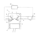
図1は、本実施例に係る内燃機関及びその吸排気系の概略構成を示す図である。内燃機関1は車両駆動用のディーゼル機関である。内燃機関1の気筒2内にはピストン3が摺動自在に設けられている。気筒2内上部の燃焼室には、吸気ポート4と排気ポート5とが接続されている。吸気ポート4および排気ポート5の燃焼室への開口部は、それぞれ吸気弁6および排気弁7によって開閉される。吸気ポート4および排気ポート5は、それぞれ吸気通路8および排気通路9に接続されている。また、気筒2には、該気筒2内に燃料を直接噴射する燃料噴射弁10が設けられている。
<Schematic configuration of internal combustion engine and intake / exhaust system thereof>
FIG. 1 is a diagram showing a schematic configuration of an internal combustion engine and its intake / exhaust system according to the present embodiment. The internal combustion engine 1 is a diesel engine for driving a vehicle. A
排気通路9には、排気中のPMを捕集するフィルタ11が設けられている。このフィルタ11には酸化触媒が担持されている。尚、フィルタ11に担持される触媒は酸化機能を有していれば良く、例えば吸蔵還元型NOx触媒であっても良い。また、フィルタ11自体には触媒が担持されず、フィルタ11より上流側の排気通路9に触媒が配置された構成としても良い。フィルタ11より下流側の排気通路9には排気の温度に対応した電気信号を出力する排気温度センサ12が設けられている。
The exhaust passage 9 is provided with a
以上述べたように構成された内燃機関1には、この内燃機関1を制御するためのECU20が併設されている。ECU20には、排気温度センサ12等の各種センサが電気配線を介して接続されており、これらの出力信号がECU20に入力される。また、ECU20には、燃料噴射弁10が電気的に接続されており、ECU20によって、この燃料噴射弁10が制御される。
The internal combustion engine 1 configured as described above is provided with an
<フィルタ再生制御>
ここで、フィルタ11に堆積したPMを酸化・除去するフィルタ再生制御について説明する。フィルタ11のPM堆積量は、燃料噴射弁10からの積算燃料噴射量等に基づいて推定される。そして、推定されたPM堆積量が後述する再生実行PM堆積量Qpm以上となった場合、本実施例では、圧縮行程上死点近傍の時期に燃料噴射弁10から燃料を噴射することで行われる主燃料噴射の後、膨張行程または排気行程において更に燃料噴射弁10から燃料を噴射することで副燃料噴射を行うことによってフィルタ再生制御を実行する。フィルタ再生制御が実行されると、副燃料噴射によって噴射された燃料がフィルタ11に担持された酸化触媒に供給され、供給された燃料が酸化触媒において酸化するときに発生する酸化熱によってフィルタ11の温度が上昇する。それによって、フィルタ11に堆積したPMが酸化し除去される。このとき、フィルタ11の温度を排気温度センサ12の検出値から推定し、推定されたフィルタ11の温度が、PMの酸化が可能であって予め定められた温度範囲内の温度となるように、副燃料噴射での燃料噴射量が制御される。また、フィルタ再生制御が実行された場合、該フィルタ再生制御の実行開始から後述する再生実行時間Δtreが経過したときに副燃料噴射が停止されてフィルタ再生制御が停止される。
<Filter regeneration control>
Here, filter regeneration control for oxidizing and removing PM deposited on the
<副燃料噴射によるオイル希釈>
上記説明したフィルタ再生制御を実行した場合、副燃料噴射は、主燃料噴射の後、即ち気筒2内おいてピストン3が上死点近傍の位置よりも下がった時期に行われるため、副燃料噴射によって噴射された燃料は主燃料噴射によって噴射された燃料に比べて気筒2内壁面に付着し易い。そのため、フィルタ再生制御実行時には燃料によるオイルの希釈が促進される虞がある。
<Oil dilution by sub fuel injection>
When the filter regeneration control described above is executed, the auxiliary fuel injection is performed after the main fuel injection, that is, at a time when the
そこで、本実施例では、燃料によるオイルの希釈度合い、即ち、オイルに混入している燃料の量(以下、燃料混入量Qfと称する)に応じて、フィルタ再生制御の実行頻度、及び、フィルタ再生制御を実行するときの実行時間を変更する。 Therefore, in this embodiment, the frequency of filter regeneration control and the filter regeneration are determined in accordance with the degree of dilution of the oil by the fuel, that is, the amount of fuel mixed in the oil (hereinafter referred to as the fuel mixed amount Qf). Change the execution time when executing control.
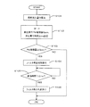
<フィルタ再生制御ルーチン>
次に、本実施例に係るフィルタ再生制御ルーチンについて図2に示すフローチャートに基づいて説明する。本ルーチンは、ECU20に予め記憶されており、内燃機関1の運転中に規定クランク角毎に繰り返し実行されるルーチンである。
<Filter regeneration control routine>
Next, the filter regeneration control routine according to the present embodiment will be described based on the flowchart shown in FIG. This routine is stored in advance in the
本ルーチンでは、ECU20は、先ずS101において、燃料混入量Qfを算出する。燃料混入量Qfの算出方法としては、前回以前のフィルタ再生制御実行毎に気筒2内壁に付着してオイルパンへ落下した落下燃料量を算出して積算し、さらに、フィルタ再生制御を実行していないときにオイルから蒸発する蒸発燃料量を算出して積算し、落下燃料量から蒸発燃料量を減算することによって算出する方法が例示出来る。
In this routine, the
次に、ECU20は、S102に進み、フィルタ再生制御の実行開始の閾値となるPM堆積量である再生実行PM堆積量Qpmと、フィルタ再生制御を実行したときの実行時間である再生実行時間Δtreとを燃料混入量Qfに基づいて設定する。
Next, the
ここで、燃料混入量Qfが多いほど再生実行PM堆積量Qpmは多くなるように設定される。再生実行PM堆積量Qpmが多くなることでフィルタ再生制御の実行頻度が減少することになる。また、燃料混入量Qfが多いほど再生実行時間Δtreは短くなるように設定される。燃料混入量Qfと再生実行PM堆積量Qpmとの関係、及び、燃料混入量Qfと再生実行時間Δtreとの関係をマップとして予めECU20に記憶させ、これらのマップから再生実行PM堆積量Qpm及び再生実行時間Δtreを導出し設定しても良い。
Here, the regeneration execution PM accumulation amount Qpm is set to increase as the fuel mixing amount Qf increases. As the regeneration execution PM accumulation amount Qpm increases, the execution frequency of the filter regeneration control decreases. Further, the regeneration execution time Δtre is set to be shorter as the fuel mixing amount Qf is larger. The relationship between the fuel mixing amount Qf and the regeneration execution PM deposition amount Qpm and the relationship between the fuel mixing amount Qf and the regeneration execution time Δtre are stored in advance in the
次に、ECU20は、S103に進み、現時点でのフィルタ11におけるPM堆積量が、S102にて設定された再生実行PM堆積量Qpm以上か否かを判別する。このS103において、肯定判定された場合、ECU20はS105に進み、否定判定された場合、ECU20は本ルーチンの実行を一旦終了する。
Next, the
S104に進んだECU20は、燃料噴射弁10からの副燃料噴射を開始することでフィルタ再生制御を実行する。
The
次に、ECU20は、S105に進み、フィルタ再生制御を開始してからの経過時間が、S102にて設定された再生実行時間Δtre以上となったか否かを判別する。このS105において、肯定判定された場合、ECU20はS106に進み、否定判定された場合、ECU20はS105を繰り返す。
Next, the
S106に進んだECU20は、フィルタ再生制御を停止して本ルーチンの実行を一旦終了する。
The
以上説明した制御ルーチンによれば、燃料混入量Qfが多いほど、フィルタ再生制御の
実行頻度が減少し、また、フィルタ再生制御を実行するときの実行時間が短くなる。その結果、燃料混入量Qfが多いほど、フィルタ再生制御の実行によって新たにオイルに混入する燃料量がより減少することになる。従って、燃料によるオイルの希釈を抑制しつつフィルタ再生制御を実行することが出来る。
According to the control routine described above, the greater the fuel mixing amount Qf, the lower the execution frequency of the filter regeneration control and the shorter the execution time when executing the filter regeneration control. As a result, the greater the fuel mixing amount Qf, the more the amount of fuel newly mixed into the oil due to the execution of the filter regeneration control. Therefore, filter regeneration control can be executed while suppressing dilution of oil with fuel.
尚、上記ルーチンを実行することで算出される燃料混入量Qfは、オイル交換がなされたときにリセットされる。 The fuel mixing amount Qf calculated by executing the above routine is reset when the oil is changed.
本実施例においては、フィルタ11でのPM堆積量が再生実行PM堆積量Qpm以上となったときにフィルタ再生制御を実行するとしたが、規定時間毎または規定走行距離毎にフィルタ再生制御をしても良い。規定時間毎にフィルタ再生制御を実行する場合は燃料混入量Qfが多いほど規定時間を長くし、規定走行距離毎にフィルタ再生制御を実行する場合は燃料混入量Qfが多いほど規定走行距離を長くする。このようにすることで、燃料混入量Qfが多いほどフィルタ再生制御の実行頻度を減少させることが出来る。
In the present embodiment, the filter regeneration control is executed when the PM accumulation amount in the
また、本実施例において、再生実行PM堆積量Qpmおよび再生実行時間Δtreのうちいずれか一方を予め定められた一定の値とし、他方のみを燃料混入量Qfに応じて変更するようにしても良い。 In the present embodiment, either one of the regeneration execution PM accumulation amount Qpm and the regeneration execution time Δtre may be set to a predetermined constant value, and only the other may be changed according to the fuel mixing amount Qf. .
さらに、本実施例においては、フィルタ再生制御を実行する際の燃料混入量Qfが多いときは、燃料混入量Qfが少ないときよりもフィルタ再生制御における副燃料噴射での噴射毎の燃料噴射量を減少させても良い。 Furthermore, in this embodiment, when the fuel mixing amount Qf when performing the filter regeneration control is large, the fuel injection amount for each injection in the sub fuel injection in the filter regeneration control is set to be smaller than when the fuel mixing amount Qf is small. It may be decreased.
副燃料噴射での噴射毎の燃料噴射量が少ないほど、該副燃料噴射によって噴射され気筒2内壁面に付着する燃料量が少なくなる。そのため、上記制御によれば、燃料混入量Qfが多いときは、燃料混入量Qfが少ないときよりもフィルタ再生制御の実行によるオイルへの燃料の混入を抑制することが出来る。即ち、フィルタ再生制御によるオイルの希釈を抑制することが出来る。
The smaller the fuel injection amount for each injection in the sub fuel injection, the smaller the fuel amount injected by the sub fuel injection and adhering to the inner wall surface of the
尚、副燃料噴射での噴射毎の燃料噴射量を減少させる場合であっても、その量を、フィルタの温度がPMの酸化が可能な温度範囲内となる量とする。 Even when the fuel injection amount for each injection in the sub fuel injection is decreased, the amount is set so that the temperature of the filter falls within a temperature range in which PM can be oxidized.
また、本実施例においては、燃料混入量Qfが多いほど、変速機の変速点を変更する等の制御によって内燃機関1の機関負荷をより低くするのが好ましい。 Further, in the present embodiment, it is preferable that the engine load of the internal combustion engine 1 is made lower by control such as changing the shift point of the transmission as the fuel mixing amount Qf increases.
内燃機関1の機関負荷を低くすることによってフィルタ11に堆積するPM量を減少させることが出来る。そのため、燃料混入量Qfが増加したときに、フィルタ再生制御の実行頻度を減少させた場合や、フィルタ再生制御を実行するときの実行時間を短くした場合であっても、フィルタ11でのPM堆積量が過剰に多くなるのを抑制することが可能となる。
By reducing the engine load of the internal combustion engine 1, the amount of PM deposited on the
<変形例>
ここで、本実施例の変形例について説明する。図3は本実施例の変形例に係る内燃機関およびその吸排気系を示す概略構成図である。この変形例の構成においてはフィルタ11より上流側の排気通路9に燃料添加弁13が設けられている。それ以外の構成は上述した図1と同様であるため説明を省略する。燃料噴射弁13はECU20と電気的に接続されており、ECU20によって制御される。
<Modification>
Here, a modification of the present embodiment will be described. FIG. 3 is a schematic configuration diagram showing an internal combustion engine and its intake / exhaust system according to a modification of the present embodiment. In this modified example, a
図3に示すように燃料添加弁13を設けた場合、フィルタ再生制御を実行する際の燃料混入量Qfが規定量以上のときは、副燃料噴射を禁止し、該副燃料噴射の代わりに燃料添
加弁13によって燃料を添加することでフィルタ再生制御を実行する。尚、ここでの規定量とは、燃料によるオイルの希釈度合いが許容範囲内となる量であって予め定められた量である。
In the case where the
副燃料噴射を燃料添加弁13からの燃料添加に代えることによって気筒2内壁面への燃料の付着を防止することが出来、その結果、フィルタ再生制御の実行によるオイルへの燃料の混入を防止することが出来る。従って、フィルタ再生制御によるオイルの希釈を抑制することが可能となる。
By substituting the fuel addition from the
本実施例に係る内燃機関及びその吸排気系の概略構成は上述した実施例1と同様であるためその説明を省略する。 Since the schematic configuration of the internal combustion engine and the intake / exhaust system thereof according to the present embodiment is the same as that of the first embodiment, the description thereof is omitted.
本実施例では、内燃機関1を備えた車両のオイル交換後の走行距離をECU20によってカウントする。そして、この走行距離がオイル交換距離を越えた場合、該走行距離が該オイル交換距離以下のときよりも、フィルタ再生制御の実行頻度を減少させると共に、フィルタ再生制御を実行するときの実行時間を短くする。
In the present embodiment, the
ここで、オイル交換距離とは、燃料によるオイルの希釈度合いが許容範囲内であると判断出来る車両の走行距離であって、オイルの種類等に応じて予め定められた値である。 Here, the oil replacement distance is a travel distance of the vehicle at which it can be determined that the degree of dilution of oil by fuel is within an allowable range, and is a value determined in advance according to the type of oil and the like.
オイル交換をしたときからの走行距離が長くなるほど燃料混入量Qfは必然的に増加するが、本実施例によれば、燃料混入量Qfがある程度増加したときには、フィルタ再生制御の実行によって新たにオイルに混入する燃料量が減少させることが出来る。従って、実施例1と同様、燃料によるオイルの希釈を抑制しつつフィルタ再生制御を実行することが出来る。 The fuel mixing amount Qf inevitably increases as the travel distance from when the oil is changed, but according to the present embodiment, when the fuel mixing amount Qf increases to some extent, the oil regeneration is newly performed by executing the filter regeneration control. The amount of fuel mixed in can be reduced. Therefore, the filter regeneration control can be executed while suppressing the dilution of the oil with the fuel, as in the first embodiment.
尚、本実施例において、フィルタ再生制御の実行頻度を減少させる方法、及び、フィルタ再生制御を実行するときの実行時間を短くする方法は、実施例1と同様である。また、本実施例においても、フィルタ再生制御の実行頻度、及び、フィルタ再生制御を実行するときの実行時間のうち一方を一定とし、他方のみをオイル交換後の車両の走行距離に応じて変更するとしても良い。 In this embodiment, the method of reducing the execution frequency of the filter regeneration control and the method of shortening the execution time when executing the filter regeneration control are the same as in the first embodiment. Also in the present embodiment, one of the execution frequency of the filter regeneration control and the execution time when the filter regeneration control is performed is made constant, and only the other is changed according to the travel distance of the vehicle after the oil change. It is also good.
また、本実施例においては、オイル交換後の車両の走行距離がオイル交換距離を越えたときは、該走行距離がオイル交換距離以下のときよりも内燃機関1の機関負荷を低くするのが好ましい。 Further, in this embodiment, when the travel distance of the vehicle after the oil change exceeds the oil change distance, it is preferable to lower the engine load of the internal combustion engine 1 than when the travel distance is equal to or less than the oil change distance. .
この場合、オイル交換後の車両の走行距離がオイル交換距離を越えたときにはフィルタ11に堆積するPM量を減少させることが出来る。そのため、車両の走行距離がオイル交換距離を越えたときに、フィルタ再生制御の実行頻度を減少させた場合や、フィルタ再生制御を実行するときの実行時間を短くした場合であっても、フィルタ11でのPM堆積量が過剰に多くなるのをより抑制することが可能となる。
In this case, when the travel distance of the vehicle after the oil change exceeds the oil change distance, the amount of PM accumulated on the
1・・・内燃機関
2・・・気筒
9・・・排気通路
10・・燃料噴射弁
11・・パティキュレートフィルタ
12・・排気温度センサ
13・・燃料添加弁
DESCRIPTION OF SYMBOLS 1 ...
Claims (7)
該パティキュレートフィルタより上流側の前記排気通路に設けられているか、もしくは、該パティキュレートフィルタに担持されている酸化機能を有する触媒と、を備え、
前記内燃機関の気筒内で主燃料噴射より後の時期に副燃料噴射を行うことによって前記触媒に燃料を供給し、それによって前記パティキュレートフィルタを昇温させて前記パティキュレートフィルタに堆積した粒子状物質を酸化・除去するフィルタ再生制御を、前記パティキュレートフィルタに堆積した粒子状物質の量が再生実行PM堆積量以上となったときに実行する内燃機関の排気浄化装置において、
オイルに混入している燃料の量を推定する燃料混入量推定手段を更に備え、
該燃料混入量推定手段によって推定された燃料の混入量が多いほど、前記再生実行PM堆積量を多く設定することで前記フィルタ再生制御の実行頻度を減少させると共に、前記フィルタ再生制御の一回あたりの実行時間を短くすることを特徴とする内燃機関の排気浄化装置。 A particulate filter provided in an exhaust passage of the internal combustion engine for collecting particulate matter in the exhaust;
Provided in the exhaust passage on the upstream side of the particulate filter, or a catalyst having an oxidation function carried on the particulate filter,
In the cylinder of the internal combustion engine, a fuel is supplied to the catalyst by performing a secondary fuel injection at a time after the main fuel injection, thereby raising the temperature of the particulate filter and depositing particles on the particulate filter. In the exhaust gas purification apparatus for an internal combustion engine that executes the filter regeneration control for oxidizing and removing the substance when the amount of the particulate matter deposited on the particulate filter exceeds the regeneration execution PM deposition amount ,
A fuel mixing amount estimating means for estimating the amount of fuel mixed in the oil;
The larger the fuel mixing amount estimated by the fuel mixing amount estimation means, the more the regeneration execution PM accumulation amount is set, so that the frequency of execution of the filter regeneration control is reduced and the filter regeneration control is performed once. An exhaust gas purification apparatus for an internal combustion engine characterized by shortening the execution time of the engine.
前記燃料混入量推定手段によって推定されたオイルに混入している燃料の量が規定量以上のときは、副燃料噴射を禁止し、該副燃料噴射の代わりに前記燃料添加弁から燃料を添加することでフィルタ再生制御を実行することを特徴とする請求項1記載の内燃機関の排気浄化装置。 When the catalyst is provided in the exhaust passage, the exhaust passage is upstream of the catalyst, and when the catalyst is supported by the particulate filter, the exhaust is upstream of the particulate filter. A fuel addition valve for adding fuel to the passage;
When the amount of fuel mixed in the oil estimated by the fuel mixing amount estimation means is equal to or greater than a specified amount, sub fuel injection is prohibited and fuel is added from the fuel addition valve instead of the sub fuel injection. 2. The exhaust gas purification apparatus for an internal combustion engine according to claim 1, wherein the filter regeneration control is executed.
、前記内燃機関の機関負荷をより低くすることを特徴とする請求項1から3のいずれかに記載の内燃機関の排気浄化装置。 Internal combustion according to the greater the amount of the mixed fuel amount estimating means fuel mixed to the estimated oil by many, one of claims 1 to 3, characterized in that the lower the engine load of the internal combustion engine Engine exhaust purification system.
該パティキュレートフィルタより上流側の前記排気通路に設けられているか、もしくは該パティキュレートフィルタに担持されている酸化機能を有する触媒と、を備え、
前記内燃機関の気筒内で主燃料噴射より後の時期に副燃料噴射を行うことによって前記触媒に燃料を供給し、それによって前記パティキュレートフィルタを昇温させて前記パティキュレートフィルタに堆積した粒子状物質を酸化・除去するフィルタ再生制御を、前記パティキュレートフィルタに堆積した粒子状物質の量が再生実行PM堆積量以上となったときに実行する内燃機関の排気浄化装置において、
前記内燃機関を備えた車両のオイル交換後の走行距離が、燃料によるオイルの希釈度合いが許容範囲内であると判断出来る走行距離であるオイル交換距離を越えた場合は、該走行距離が該オイル交換距離以下のときよりも、前記再生実行PM堆積量を多く設定することで前記フィルタ再生制御の実行頻度を減少させると共に、前記フィルタ再生制御の一回あたりの実行時間を短くすることを特徴とする内燃機関の排気浄化装置。 A particulate filter provided in an exhaust passage of the internal combustion engine for collecting particulate matter in the exhaust;
Provided in the exhaust passage upstream of the particulate filter, or a catalyst having an oxidation function carried on the particulate filter,
In the cylinder of the internal combustion engine, a fuel is supplied to the catalyst by performing a secondary fuel injection at a time after the main fuel injection, thereby raising the temperature of the particulate filter and depositing particles on the particulate filter. In the exhaust gas purification apparatus for an internal combustion engine that executes the filter regeneration control for oxidizing and removing the substance when the amount of the particulate matter deposited on the particulate filter exceeds the regeneration execution PM deposition amount ,
If the mileage after oil change of the vehicle equipped with the internal combustion engine exceeds the oil exchange distance, which is a mileage at which it can be determined that the degree of dilution of oil with fuel is within an allowable range, the mileage The filter regeneration control execution frequency is reduced by setting the regeneration execution PM accumulation amount to be larger than when the exchange distance is less than or less, and the execution time per filter regeneration control is shortened. An exhaust purification device for an internal combustion engine.
Priority Applications (4)
| Application Number | Priority Date | Filing Date | Title |
|---|---|---|---|
| JP2004210439A JP4504753B2 (en) | 2004-07-16 | 2004-07-16 | Exhaust gas purification device for internal combustion engine |
| DE602005000312T DE602005000312T2 (en) | 2004-07-16 | 2005-07-14 | A particulate filter regeneration system that compensates for the oil burned in the cylinder. |
| EP05015331A EP1617059B1 (en) | 2004-07-16 | 2005-07-14 | A particle filter regenration system which compensates for oil burnt in the combustion chamber |
| CN2005100848914A CN1721663B (en) | 2004-07-16 | 2005-07-18 | Exhaust purifying device for internal combustion engine |
Applications Claiming Priority (1)
| Application Number | Priority Date | Filing Date | Title |
|---|---|---|---|
| JP2004210439A JP4504753B2 (en) | 2004-07-16 | 2004-07-16 | Exhaust gas purification device for internal combustion engine |
Publications (2)
| Publication Number | Publication Date |
|---|---|
| JP2006029235A JP2006029235A (en) | 2006-02-02 |
| JP4504753B2 true JP4504753B2 (en) | 2010-07-14 |
Family
ID=34937850
Family Applications (1)
| Application Number | Title | Priority Date | Filing Date |
|---|---|---|---|
| JP2004210439A Expired - Fee Related JP4504753B2 (en) | 2004-07-16 | 2004-07-16 | Exhaust gas purification device for internal combustion engine |
Country Status (4)
| Country | Link |
|---|---|
| EP (1) | EP1617059B1 (en) |
| JP (1) | JP4504753B2 (en) |
| CN (1) | CN1721663B (en) |
| DE (1) | DE602005000312T2 (en) |
Families Citing this family (15)
| Publication number | Priority date | Publication date | Assignee | Title |
|---|---|---|---|---|
| JP4642546B2 (en) * | 2005-05-13 | 2011-03-02 | 本田技研工業株式会社 | Exhaust gas purification device for internal combustion engine |
| DE102006009099A1 (en) * | 2006-02-28 | 2007-08-30 | Daimlerchrysler Ag | Fuel injection system for use in e.g. diesel internal combustion engine, has pressure regulating valve that is arranged between check valve and dosing valve and is connected with system by outlet |
| JP4513785B2 (en) * | 2006-06-21 | 2010-07-28 | トヨタ自動車株式会社 | Exhaust gas purification device for internal combustion engine |
| DE102006034521B4 (en) * | 2006-07-26 | 2015-10-29 | Ford Global Technologies, Llc | Method for controlling a motor oil dilution of an internal combustion engine |
| JP4312225B2 (en) | 2006-11-09 | 2009-08-12 | トヨタ自動車株式会社 | In-vehicle diesel engine |
| FR2920824B1 (en) * | 2007-09-07 | 2015-07-03 | Renault Sas | METHOD FOR MANAGING THE OPERATION OF AT LEAST ONE CATALYTIC CONVERTER FOR INTERNAL COMBUSTION ENGINE |
| DE102008042784B4 (en) * | 2008-10-13 | 2016-01-28 | Ford Global Technologies, Llc | A method of operating a direct injection internal combustion engine having at least one exhaust aftertreatment system |
| WO2010073876A1 (en) * | 2008-12-24 | 2010-07-01 | トヨタ自動車株式会社 | Control device for vehicle |
| JP5124541B2 (en) * | 2009-08-05 | 2013-01-23 | 本田技研工業株式会社 | Engine oil replacement judgment device |
| CN101975104A (en) * | 2010-11-15 | 2011-02-16 | 中国环境科学研究院 | Oxidation type catalyst-assisting regeneration system for diesel particulate filter (DPF) |
| US8959898B2 (en) | 2011-04-26 | 2015-02-24 | GM Global Technology Operations LLC | Regeneration methods and systems for particulate filters |
| US9080494B2 (en) * | 2011-06-07 | 2015-07-14 | GM Global Technology Operations LLC | Particulate filter monitoring methods and systems |
| JP5838736B2 (en) * | 2011-11-07 | 2016-01-06 | 三菱自動車工業株式会社 | Exhaust purification equipment |
| JP7058565B2 (en) * | 2018-06-26 | 2022-04-22 | 三菱化工機株式会社 | Solid component separator controller, solid component separator, marine exhaust gas scrubber system, and marine diesel engine |
| CN110425023B (en) * | 2019-07-02 | 2020-12-04 | 一汽解放汽车有限公司 | Regeneration control method and device for diesel particulate filter, vehicle and storage medium |
Family Cites Families (8)
| Publication number | Priority date | Publication date | Assignee | Title |
|---|---|---|---|---|
| JP3932729B2 (en) | 1999-09-03 | 2007-06-20 | トヨタ自動車株式会社 | Exhaust gas purification device for internal combustion engine |
| JP3680258B2 (en) | 2000-02-25 | 2005-08-10 | トヨタ自動車株式会社 | Exhaust gas purification device for internal combustion engine |
| JP2001323835A (en) | 2000-05-15 | 2001-11-22 | Toyota Motor Corp | Exhaust emission control device for internal combustion engine |
| JP3846309B2 (en) * | 2001-02-05 | 2006-11-15 | 日産自動車株式会社 | Exhaust purification device |
| US6622480B2 (en) * | 2001-02-21 | 2003-09-23 | Isuzu Motors Limited | Diesel particulate filter unit and regeneration control method of the same |
| JP2002371900A (en) | 2001-06-19 | 2002-12-26 | Isuzu Motors Ltd | Fuel injection control method in internal combustion engine |
| JP3736417B2 (en) | 2001-10-10 | 2006-01-18 | トヨタ自動車株式会社 | Exhaust gas purification device for internal combustion engine |
| JP2004211638A (en) * | 2003-01-07 | 2004-07-29 | Nissan Motor Co Ltd | Filter regeneration control system of diesel engine |
-
2004
- 2004-07-16 JP JP2004210439A patent/JP4504753B2/en not_active Expired - Fee Related
-
2005
- 2005-07-14 EP EP05015331A patent/EP1617059B1/en not_active Expired - Fee Related
- 2005-07-14 DE DE602005000312T patent/DE602005000312T2/en active Active
- 2005-07-18 CN CN2005100848914A patent/CN1721663B/en not_active Expired - Fee Related
Also Published As
| Publication number | Publication date |
|---|---|
| EP1617059B1 (en) | 2006-12-06 |
| DE602005000312T2 (en) | 2007-06-21 |
| CN1721663B (en) | 2010-12-15 |
| CN1721663A (en) | 2006-01-18 |
| JP2006029235A (en) | 2006-02-02 |
| DE602005000312D1 (en) | 2007-01-18 |
| EP1617059A1 (en) | 2006-01-18 |
Similar Documents
| Publication | Publication Date | Title |
|---|---|---|
| EP1617059B1 (en) | A particle filter regenration system which compensates for oil burnt in the combustion chamber | |
| EP1722087B1 (en) | Exhaust gas purifying apparatus for internal combustion engine | |
| EP2079916B1 (en) | Vehicle diesel engine and control method of the same | |
| CN108301900B (en) | Exhaust gas purification device for internal combustion engine and exhaust gas purification method for internal combustion engine | |
| JP4922876B2 (en) | Exhaust gas purification system for internal combustion engine | |
| US20090044517A1 (en) | Exhaust gas purification system for an internal combustion engine | |
| JP2005214178A (en) | Exhaust emission control device for internal combustion engine | |
| JP2008111428A (en) | Exhaust gas temperature control method and exhaust gas temperature control device of internal combustion engine, and internal combustion engine system | |
| JP2007002689A (en) | Control device for internal combustion engine | |
| JP4003768B2 (en) | Exhaust gas purification system for internal combustion engine | |
| JP4269927B2 (en) | Exhaust gas purification system for internal combustion engine | |
| JP2008038779A (en) | Exhaust emission control device of internal combustion engine | |
| JP5731343B2 (en) | Exhaust gas purification system for internal combustion engine | |
| JP4095979B2 (en) | Exhaust gas purification device for internal combustion engine | |
| JP2011106340A (en) | Exhaust gas purification system for internal combustion engine | |
| JP4779785B2 (en) | Engine exhaust system temperature control device | |
| WO2014132443A1 (en) | Exhaust purification device for spark-ignited internal combustion engine | |
| JP2012026428A (en) | Exhaust emission control device of internal combustion engine | |
| JP2006220036A (en) | Control system for hybrid engine with filter | |
| JP6102856B2 (en) | Exhaust gas purification device for internal combustion engine | |
| JP2010196704A (en) | Method for regenerating exhaust gas post-treatment device | |
| JP4144504B2 (en) | Exhaust gas purification device for internal combustion engine | |
| JP4849823B2 (en) | Particulate filter regeneration control device | |
| JP4406255B2 (en) | Method for maintaining catalyst temperature of internal combustion engine | |
| JP4062229B2 (en) | Exhaust gas purification device for internal combustion engine |
Legal Events
| Date | Code | Title | Description |
|---|---|---|---|
| A977 | Report on retrieval |
Free format text: JAPANESE INTERMEDIATE CODE: A971007 Effective date: 20071101 |
|
| A131 | Notification of reasons for refusal |
Free format text: JAPANESE INTERMEDIATE CODE: A131 Effective date: 20071218 |
|
| A521 | Written amendment |
Free format text: JAPANESE INTERMEDIATE CODE: A523 Effective date: 20080218 |
|
| A02 | Decision of refusal |
Free format text: JAPANESE INTERMEDIATE CODE: A02 Effective date: 20080617 |
|
| A521 | Written amendment |
Free format text: JAPANESE INTERMEDIATE CODE: A523 Effective date: 20080808 |
|
| A911 | Transfer to examiner for re-examination before appeal (zenchi) |
Free format text: JAPANESE INTERMEDIATE CODE: A911 Effective date: 20080825 |
|
| A912 | Re-examination (zenchi) completed and case transferred to appeal board |
Free format text: JAPANESE INTERMEDIATE CODE: A912 Effective date: 20080926 |
|
| A521 | Written amendment |
Free format text: JAPANESE INTERMEDIATE CODE: A523 Effective date: 20100308 |
|
| A01 | Written decision to grant a patent or to grant a registration (utility model) |
Free format text: JAPANESE INTERMEDIATE CODE: A01 |
|
| A61 | First payment of annual fees (during grant procedure) |
Free format text: JAPANESE INTERMEDIATE CODE: A61 Effective date: 20100423 |
|
| R151 | Written notification of patent or utility model registration |
Ref document number: 4504753 Country of ref document: JP Free format text: JAPANESE INTERMEDIATE CODE: R151 |
|
| FPAY | Renewal fee payment (event date is renewal date of database) |
Free format text: PAYMENT UNTIL: 20130430 Year of fee payment: 3 |
|
| FPAY | Renewal fee payment (event date is renewal date of database) |
Free format text: PAYMENT UNTIL: 20130430 Year of fee payment: 3 |
|
| LAPS | Cancellation because of no payment of annual fees |