EP1228812A1 - A method and an apparatus for applying a surface coating on edges of a mineral fibre board - Google Patents
A method and an apparatus for applying a surface coating on edges of a mineral fibre board Download PDFInfo
- Publication number
- EP1228812A1 EP1228812A1 EP01200351A EP01200351A EP1228812A1 EP 1228812 A1 EP1228812 A1 EP 1228812A1 EP 01200351 A EP01200351 A EP 01200351A EP 01200351 A EP01200351 A EP 01200351A EP 1228812 A1 EP1228812 A1 EP 1228812A1
- Authority
- EP
- European Patent Office
- Prior art keywords
- coating
- edge
- fibre board
- mineral fibre
- applicator roller
- Prior art date
- Legal status (The legal status is an assumption and is not a legal conclusion. Google has not performed a legal analysis and makes no representation as to the accuracy of the status listed.)
- Withdrawn
Links
- 238000000576 coating method Methods 0.000 title claims abstract description 139
- 239000011248 coating agent Substances 0.000 title claims abstract description 134
- 239000000835 fiber Substances 0.000 title claims abstract description 89
- 229910052500 inorganic mineral Inorganic materials 0.000 title claims abstract description 73
- 239000011707 mineral Substances 0.000 title claims abstract description 73
- 238000000034 method Methods 0.000 title claims abstract description 34
- 239000012530 fluid Substances 0.000 claims description 58
- 230000002093 peripheral effect Effects 0.000 claims description 21
- 230000005540 biological transmission Effects 0.000 claims description 12
- 239000000463 material Substances 0.000 claims description 12
- 230000001413 cellular effect Effects 0.000 claims description 6
- 229920001971 elastomer Polymers 0.000 claims description 6
- 229910000831 Steel Inorganic materials 0.000 claims description 4
- 238000005086 pumping Methods 0.000 claims description 4
- 239000010959 steel Substances 0.000 claims description 4
- 230000002745 absorbent Effects 0.000 claims description 2
- 239000002250 absorbent Substances 0.000 claims description 2
- 230000003019 stabilising effect Effects 0.000 claims description 2
- 239000005002 finish coating Substances 0.000 claims 2
- 238000010408 sweeping Methods 0.000 claims 1
- 239000003973 paint Substances 0.000 description 7
- 210000002268 wool Anatomy 0.000 description 6
- 239000011347 resin Substances 0.000 description 5
- 229920005989 resin Polymers 0.000 description 5
- 238000010422 painting Methods 0.000 description 4
- 230000001105 regulatory effect Effects 0.000 description 4
- 239000011247 coating layer Substances 0.000 description 3
- 238000005728 strengthening Methods 0.000 description 3
- 230000006835 compression Effects 0.000 description 2
- 238000007906 compression Methods 0.000 description 2
- 238000006073 displacement reaction Methods 0.000 description 2
- 239000010410 layer Substances 0.000 description 2
- 238000004519 manufacturing process Methods 0.000 description 2
- 230000035515 penetration Effects 0.000 description 2
- XLYOFNOQVPJJNP-UHFFFAOYSA-N water Substances O XLYOFNOQVPJJNP-UHFFFAOYSA-N 0.000 description 2
- NIXOWILDQLNWCW-UHFFFAOYSA-N acrylic acid group Chemical group C(C=C)(=O)O NIXOWILDQLNWCW-UHFFFAOYSA-N 0.000 description 1
- 210000003850 cellular structure Anatomy 0.000 description 1
- 230000000295 complement effect Effects 0.000 description 1
- 238000009413 insulation Methods 0.000 description 1
- 239000011490 mineral wool Substances 0.000 description 1
- 230000007903 penetration ability Effects 0.000 description 1
- 230000003014 reinforcing effect Effects 0.000 description 1
- 238000005096 rolling process Methods 0.000 description 1
- 229920006395 saturated elastomer Polymers 0.000 description 1
- 238000009738 saturating Methods 0.000 description 1
- 239000007779 soft material Substances 0.000 description 1
- 238000009987 spinning Methods 0.000 description 1
- 238000009827 uniform distribution Methods 0.000 description 1
Images



Classifications
-
- B—PERFORMING OPERATIONS; TRANSPORTING
- B05—SPRAYING OR ATOMISING IN GENERAL; APPLYING FLUENT MATERIALS TO SURFACES, IN GENERAL
- B05C—APPARATUS FOR APPLYING FLUENT MATERIALS TO SURFACES, IN GENERAL
- B05C1/00—Apparatus in which liquid or other fluent material is applied to the surface of the work by contact with a member carrying the liquid or other fluent material, e.g. a porous member loaded with a liquid to be applied as a coating
- B05C1/006—Apparatus in which liquid or other fluent material is applied to the surface of the work by contact with a member carrying the liquid or other fluent material, e.g. a porous member loaded with a liquid to be applied as a coating for applying liquid or other fluent material to the edges of essentially flat articles
-
- B—PERFORMING OPERATIONS; TRANSPORTING
- B05—SPRAYING OR ATOMISING IN GENERAL; APPLYING FLUENT MATERIALS TO SURFACES, IN GENERAL
- B05C—APPARATUS FOR APPLYING FLUENT MATERIALS TO SURFACES, IN GENERAL
- B05C1/00—Apparatus in which liquid or other fluent material is applied to the surface of the work by contact with a member carrying the liquid or other fluent material, e.g. a porous member loaded with a liquid to be applied as a coating
- B05C1/04—Apparatus in which liquid or other fluent material is applied to the surface of the work by contact with a member carrying the liquid or other fluent material, e.g. a porous member loaded with a liquid to be applied as a coating for applying liquid or other fluent material to work of indefinite length
- B05C1/08—Apparatus in which liquid or other fluent material is applied to the surface of the work by contact with a member carrying the liquid or other fluent material, e.g. a porous member loaded with a liquid to be applied as a coating for applying liquid or other fluent material to work of indefinite length using a roller or other rotating member which contacts the work along a generating line
- B05C1/0813—Apparatus in which liquid or other fluent material is applied to the surface of the work by contact with a member carrying the liquid or other fluent material, e.g. a porous member loaded with a liquid to be applied as a coating for applying liquid or other fluent material to work of indefinite length using a roller or other rotating member which contacts the work along a generating line characterised by means for supplying liquid or other fluent material to the roller
-
- B—PERFORMING OPERATIONS; TRANSPORTING
- B05—SPRAYING OR ATOMISING IN GENERAL; APPLYING FLUENT MATERIALS TO SURFACES, IN GENERAL
- B05C—APPARATUS FOR APPLYING FLUENT MATERIALS TO SURFACES, IN GENERAL
- B05C1/00—Apparatus in which liquid or other fluent material is applied to the surface of the work by contact with a member carrying the liquid or other fluent material, e.g. a porous member loaded with a liquid to be applied as a coating
- B05C1/04—Apparatus in which liquid or other fluent material is applied to the surface of the work by contact with a member carrying the liquid or other fluent material, e.g. a porous member loaded with a liquid to be applied as a coating for applying liquid or other fluent material to work of indefinite length
- B05C1/08—Apparatus in which liquid or other fluent material is applied to the surface of the work by contact with a member carrying the liquid or other fluent material, e.g. a porous member loaded with a liquid to be applied as a coating for applying liquid or other fluent material to work of indefinite length using a roller or other rotating member which contacts the work along a generating line
- B05C1/0817—Apparatus in which liquid or other fluent material is applied to the surface of the work by contact with a member carrying the liquid or other fluent material, e.g. a porous member loaded with a liquid to be applied as a coating for applying liquid or other fluent material to work of indefinite length using a roller or other rotating member which contacts the work along a generating line characterised by means for removing partially liquid or other fluent material from the roller, e.g. scrapers
Definitions
- the applicator roller has a frusto-conical periphery on at least a part of the periphery, and the transmission roller and the applicator roller are arranged with an angle between the axis of rotation of the rollers of substantially 90° minus half the top angle of the frusto-conical peripheral contact surface of the applicator roller.
- a relatively compact design of the coating station may be achieved and an efficient transfer of the coating fluid is achieved, since a full contact between the relevant surfaces on the rollers is ensured.
- the applicator rollers 6 in this embodiment are designed similarly to the rollers 6 in the first embodiment with a peripheral profile corresponding to the edge profile 10 of the mineral fibre board 1 to be coated.
- the object achieved by this embodiment is a process for providing edges on mineral fibre boards with improved strength.
- the type of coating fluid may therefore be selected among paints with high penetration capabilities and less surface covering properties.
- the smoothness of the coated edges may not be in finishing quality, but this could be applied by running the fibre boards through a machine according to the first embodiment afterwards.
Landscapes
- Coating Apparatus (AREA)
Abstract
The present invention concerns a method and an apparatus for applying a surface
coating on edges of a mineral fibre board. In order to obtain a more uniform edge
coating in particular by more complex edge profiles, the invention describes a
method and an apparatus for applying a surface coating on edges of a mineral fibre
board wherein the applicator roller of the coating station is provided with a profiled
perimeter edge corresponding to at least a portion of the profile geometry of the first
edge to be coated on the mineral fibre board. Hereby a simple and cost effective
process and apparatus is provided for achieving a strong, uniform edge coating on a
mineral fibre board.
Description
- The present invention relates to the field of a method and an apparatus for applying a surface coating on edges of a mineral fibre board for aesthetic purposes and in order to obtain a coating for strengthening the edges..
- From British patent No.
GB 1 394 621 a method of strengthening edges of fibrous sheet material is known. By this method a resin is applied to two opposite edges of a rectangular board simultaneously by a pair of applying roller arrangements positioned on opposite sides of a conveyor arrangement. Each roller arrangement comprises an applicator roller that is partly submerged in a bath of resin and a doctor blade that limits the amount of resin on the applicator roller before the resin is deposited on the edges of the fibre board. Though the position of the doctor blade is adjustable, the amounts of coating resin transferred to the edges are inaccurate by this method. This inaccuracy leads to an uneven coating layer on the board and increases when the speed of the process is increased. Moreover, this method is unsuitable for coating an edge with an uneven geometry. Another problem with the more complex geometry is to ensure a saturation of the edge region in order to strengthening the edges and to prevent flakes of coating from falling off. - Today, mineral fibre boards are manufactured with very different densities depending on the use of the mineral fibre board, ranging from insulation batts or panels with low density (about 80 - approx. 145 kg/m3) to boards or tiles with somewhat higher densities (> 200 kg/m3) for use as e.g. ceiling panels. In particular - but not exclusively - in the latter case, particular shapes of the edge regions may be provided for assembly purposes. This makes it desirable to provide an efficient and cost-effective production process for painting the edges on the boards.
- Therefore, it is an object of the invention to provide a method and an apparatus for applying a surface coating on edges of a mineral fibre board with relatively complex edge geometry in a cost-effective manner. Another object is to provide a method and an apparatus for obtaining a uniform surface coating on the edges of a mineral fibre board. Still another object of the invention is to provide a method and an apparatus for saturating the edge region of a mineral fibre board with the surface coating.
- The invention consists of a method and an apparatus for applying a surface coating on edges of a mineral fibre board having a first and second edge situated opposite of each other, said apparatus comprising conveying means for transporting the mineral fibre board through the apparatus in a transport direction generally parallel to the first and second edges, at least one coating station comprising an applicator roller for applying a surface coating to the first edge of the mineral fibre board, a reservoir containing a coating fluid, and means for supplying the coating fluid to the applicator roller, counter support means for supporting the second edge of the mineral fibre board during the surface coating of the opposite edge for stabilising the mineral fibre board on the conveyor means in co-operation with the applicator roller, wherein said applicator roller having a profiled perimeter edge corresponding to at least a portion of the profile geometry of the first edge to be coated on the mineral fibre board.
- By the present invention, a method and an apparatus is provided whereby it is possible to obtain a uniform coating layer on the edges of a mineral fibre board, also by more complex edge profiles. This is particularly advantageous in the coating of mineral fibre panels for e.g. ceilings as the panel boards can be supplied with a painting in the edge regions with a quality finish.
- By profiling the applicator roller, a uniform layer of coating, i.e. paint, can be applied to the different edge surfaces. The resulting edge coating achieved by the invention provides the mineral fibre board with a satisfactory finish that does not require any further treatment. Moreover, edge coating according to the process of the invention may be performed at a relatively high process speed as it is ensured that a well-defined amount of coating fluid is applied to the edges in an adequate amount so that the coating covers the surface of the mineral fibre wool that has a surface that is inhomogeneous with apertures, loose wool or other irregularities. By the method according to the invention, a wide range of coating fluids with different viscosity may be used. The mineral fibre board can be either batts with low density or relatively high density fibre boards, so-called tiles.
- The profile of the applicator rollers corresponds to at least partly to the profile of the edge of the board. Sometimes, it is sufficient to coat only the visible a part of the edge of the mineral fibre panel, or only the visible part is coated a second time.
- Preferably, the profiled perimeter includes a plurality of peripheral surfaces and the applicator roller is arranged with an inclination towards the edge to be coated. Hereby, the fibre board is held firmly against the conveyor means as the applicator roller provide a slight downwardly directed force on the fibre board.
- In the preferred embodiment of the invention, the counter support means is a second coating station for simultaneous surface coating of the opposite second edge. Hereby two edges are coated simultaneously. The second coating station is similar to the first coating station in its design.
- In an embodiment of the invention, the profiled perimeter of the applicator roller of the opposing second coating station is different from that of the applicator roller of the first coating station. Hereby fibre boards with different, e.g. complementary edge profiles may be coated in a single run through the edge coating apparatus.
- When the applicator roller is rotated with a peripheral velocity substantially equal to the transport velocity of the mineral fibre board, it is ensured that the applicator roller "rolls" the coating onto the edge region of the fibre board ensuring an even layer of coating fluid along the edge.
- In a first embodiment of the invention, the coating fluid supply means includes at least one transmitting roller that is partly immersed in the reservoir and that is in peripheral contact with the applicator roller for transferring the coating fluid onto the applicator roller. Hereby, the amount of coating fluid supplied to the applicator roller may be controlled in a precise manner. The transmission roller may be provided with a profile corresponding to the peripheral profile of the applicator roller in order to distribute the coating fluid evenly on the periphery of the applicator roller.
- In the first embodiment of the invention, the transmission roller is a hard roller and the applicator roller is a soft roller provided with at least a peripheral region in an absorbent material, such as cellular rubber or similar spongy material. Hereby, it is ensured the applicator roller that a well-defined amount of coating fluid is painted onto the edges of the mineral fibre boards.
- Preferably, the applicator roller has a frusto-conical periphery on at least a part of the periphery, and the transmission roller and the applicator roller are arranged with an angle between the axis of rotation of the rollers of substantially 90° minus half the top angle of the frusto-conical peripheral contact surface of the applicator roller. Hereby, a relatively compact design of the coating station may be achieved and an efficient transfer of the coating fluid is achieved, since a full contact between the relevant surfaces on the rollers is ensured.
- Preferably, the transmission roller and the applicator rollers are rotated in the same direction, whereby the movements in the contact zone of the two rollers are oppositely directed. As the rotation velocity of the transmission roller is variable relative to the rotation velocity of the applicator roller, the amount of coating fluid transferred to the applicator roller may be regulated. In addition, the angle and/or the contact pressure between the two rollers may also be adjusted in order to transfer the prescribed amount of coating fluid.
- In a second embodiment of the invention, the coating fluid supply means includes pumping means and a supply conduit for providing a flow of coating fluid from the reservoir onto the upper surface of the applicator roller, said upper surface being inclined towards the edge to be coated. Hereby, a method and an apparatus is achieved wherein the edge region is strengthened as the edge region of a mineral fibre board is saturated with the surface coating fluid. Since the coating fluid by this embodiment of the invention penetrates into the fibre wool in the edge region, the obtained edge coating layer is very well attached and the risk of damaging the edge coating so that it "flakes off' is considerably reduced. A coating fluid with a predetermined viscosity may preferably be chosen when strong edges are required. The viscosity may be determined with respect to the density of the mineral fibre wool and the desired penetration of the fluid into the surface region.
- In order to ensure that the supplied coating fluid is directed towards the edge of the mineral fibre board to be coated, a doctor blade is provided in association with the upper surface for removing coating fluid from said surface.
- Preferably, in the second embodiment, the applicator roller is a hard roller, such as a roller of steel, a hard polymeric material or the like. Hereby, a smooth upper surface is achieved whereby the flow friction of the coating fluid towards the periphery of the applicator roller is minimised.
- In order to ensure a good finish in a single run, two coating stations arranged successively in the transport direction at each side of the mineral fibre board. Hereby, it is ensured that a good finish is achieved in a cost effective manner.
- Preferably, a second conveying means with a second transport direction generally orthogonal relative to the first transport direction is provided for conveying the partly edge-coated fibre board to one or more sets of further coating stations arranged at the second conveyor means for applying surface coating to the remaining edges of the rectangular mineral fibre board. Hereby, a rectangular mineral fibre board may be coated on all four side edges relatively quickly and without unnecessary intermediate handling of the mineral fibre boards.
- The invention is described in detail in the following with reference to the accompanying drawings, in which:
- fig. 1
- is a schematic top view of an apparatus according to a first embodiment of the invention,
- fig. 2
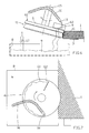
- is a detailed view of a coating station according to the first embodiment of the invention,
- fig. 3
- is a detailed view of the edge coating process according to the invention,
- fig. 4
- is a top view of the roller in the first embodiment of the invention,
- fig. 5
- is a schematic side view of same,
- fig. 6
- is a schematic side view of a second embodiment of the invention,
- fig. 7
- is a schematic top view of the same, and
- fig. 8
- is a list of edge profiles of mineral fibre boards.
- Figure 1 shows a surface coating plant for applying a coating on the
edges 10 of amineral fibre board 1. The apparatus includes a first and second coating arrangements for painting twoopposite edges 10a, 10b of a mineral fibre board in the first coating process and subsequently painting the remaining second set ofedges conveyor belts 103 for conveying themineral fibre boards 1 in a second conveyor direction generally orthogonal to the first conveyor direction. - Along each side of the first conveyor means a pair of
edge coating stations edge coating stations mineral fibre boards 1 through the equipment once or twice and/or through two of thecoating stations - In the figures 2 to 5, a
coating station applicator roller 6 that is supplied withcoating fluid 9 contained in acontainer bin 8 underneath therollers coating fluid 9 is transferred to theapplicator roller 6 by at least onetransfer roller 7. The profile ofperiphery 11 of theapplicator roller 6 corresponds to theedge profile 10 of themineral fibre board 1. Theboards 1 is forwarded by theconveyor belts 3 whereby the edge of the board is brought in contact with theapplicator rollers 6 of the twocoating stations - The
applicator roller 6 is made of a soft material, e.g. cellular rubber or similar spongy material. Theroller 6 is pressed against theedge 10 of theboard 1 with a slight pressure whilst theroller 6 is rolling on theedge 10. The peripheral velocity of theapplicator roller 6 is substantially equal to the conveyor speed of theconveyor belts 3. The coating fluid, i.e. paint, that is on theroller periphery 11 is then deposited on theedge 10 of themineral fibre board 1 or at least a predetermined portion of theedge 10, such as shown in fig. 3. A counter pressure equivalent to the slight pressure applied by theapplicator roller 6 of thefirst coating station 4 is simultaneously applied to the opposite side edge of the board, preferably by asecond applicator roller 6 of asecond coating station 5 situated opposite the first coating station 4 (see fig. 1). - The coating fluid is transferred to the
applicator roller 6 by thetransfer roller 7. Thetransfer roller 7 is partly submerged in a bath ofcoating fluid 9 in acontainer 8. A portion of coating fluid sticks to the surface of thetransfer roller 7 and is lifted out of the bath and up to the contact area between thetransfer roller 7 and theapplicator roller 6, where the coating fluid is transferred from thetransfer roller 7 to theapplicator roller 6 due to a relative movement between the tworollers transfer roller 7 may be provided with a profiled shape corresponding to that of theapplicator roller 6, such as shown in fig. 2 and 5, or - as an alternative - merely be provided with a plane surface, as shown in fig. 4 exploiting the resiliency of the periphery of theapplicator roller 6 due to the material. - The
transfer roller 7 slides on theapplicator roller 6, preferably due to a different direction of rotation of the tworollers 6, 7 (as indicated by the arrows in fig. 2). By regulating the rotation velocity of thetransfer roller 7, the amount of paint transferred from thetransfer roller 7 to theapplicator roller 6 is controlled. Hereby the amount of paint that is deposited on the edge of themineral fibre board 1 may be regulated. By high velocity on the transfer roller 7 a large amount ofcoating fluid 9 is transferred onto theapplicator roller 6 and vice versa by low velocity. - The velocities of the
applicator roller 6 and the conveyor 3 (that are equal) are normally about 20-60 m/min. The peripheral velocity of theapplicator roller 6 is calculated from a certain reference diameter DR - a kind of medium diameter, as theapplicator roller 6 does not display a well defined diameter due to the profiled shape of the periphery. The velocity of thetransfer roller 7 is preferably regulated within a range of 60 % more or less relative to the velocity of theapplicator roller 6. - The
applicator roller 6 is assembled around ashaft 13 with a hub onto which a disc of cellular rubber is provided. The particular profile of the periphery is then prepared by a grinding process or the like so that it is ensured that theroller 6 and itsperiphery 11 is concentric. - The material for the peripheral disc of the
applicator roller 6 may be a cellular rubber with a closed cellular structure, a hardness of 20-40 shore 00, a water absorbency of less than 5 %, and a compression resistance in the area of 350-650 g/cm2 to 25 % compression. - The elasticity of the material makes it possible to coat the
edges 10 with an inhomogeneous structure that is characteristic for mineral fibre wool products. It is imperative that the panel or board maintains its shape and planar position throughout the edge coating process so that it is able to absorb the elastic force from theapplicator rollers 6 on the opposite sides of thefibre board 1. - The elasticity in the cellular rubber material makes it possible to produce mineral fibre panels with coarse tolerances. The different edge profiles of the fibre boards (see some examples thereof in figure 8) makes it necessary to use
different applicator rollers 6 with correspondingperipheral profiles 11. However, as shown in fig. 4, it is not necessary to exchange thetransfer rollers 7 according the peripheral profile of theapplicator roller 6. The angle between thedrive shafts applicator roller 6 and thetransfer roller 7, respectively, is adjustable so that a full contact between the profiles of the tworollers applicator roller 6 even through the profiles of therollers board 1 and theapplicator roller 6, and between the tworollers - The coating fluid may be water based acrylic paint with a suitable viscosity. Moreover, the coating fluid may be selected according to desired properties of the edge coating, including requirements such as penetration ability and covering capability.
- A second embodiment of the invention, is shown in figures 6 and 7. In this embodiment, the
applicator roller 6 is a hard roller made of steel or the like. In this embodiment, the edge coating apparatus is designed in the same manner as in the first embodiment with one or more rollers along a first conveyor and the same along a second conveyor with an angular displacement between the two conveyors. The angular displacement may be achieved by rotation means turning the mineral fibre boards between the two aligned conveyors or by setting up the two conveyors with a mutual angle. - In the second embodiment, the
coating fluid 9 is supplied directly on theupper surface 61 of theapplicator roller 6, such as shown in fig. 6. Thecoating fluid 9 is supplied by pumping means 17 from thereservoir 8 underneath the coating station. Since theapplicator roller 6 is tilted, the upper surface is inclined towards theedge 10 of themineral fibre board 1 and the coating fluid will flow along thesurface 61 and onto the profiledperiphery 11 of theapplicator roller 6. Theapplicator roller 6 has the same velocity as theconveyor 3 and thecoating fluid 9 is deposited on theedge region 10 of themineral fibre board 1. Due to the surplus amount of paint, and thesteel roller 6, the coating fluid is forced deeper into the mineral wool of edge region reinforcing theedge 10 of themineral fibre board 1. - The
coating fluid 9 is dispensed onto the rotatingupper surface 61 of theapplicator roller 6 through thenozzle 18 of apipe 16 that is connected to the pump means 17. Since theroller 6 is spinning, thecoating fluid 9 is centrifuged towards theperipheral region 11 of theroller 6. At theupper surface 61, ascraper 62 may be arranged to ensure that surplus amounts ofcoating fluid 9 is removed from the upper surface, prior to the coating of the edge, i.e. prior to the point where theapplicator roller 6 and theedge 10 of theboard 1 makes contact. - The surplus amount of
fluid 9 is collected by thereservoir 8 underneath the coating station and reused by the pumping means 17. - The
applicator rollers 6 in this embodiment are designed similarly to therollers 6 in the first embodiment with a peripheral profile corresponding to theedge profile 10 of themineral fibre board 1 to be coated. The object achieved by this embodiment is a process for providing edges on mineral fibre boards with improved strength. The type of coating fluid may therefore be selected among paints with high penetration capabilities and less surface covering properties. The smoothness of the coated edges may not be in finishing quality, but this could be applied by running the fibre boards through a machine according to the first embodiment afterwards. - It is understood that many variations of the embodiments described above may be performed without departing from the scope of the invention as set forth in the accompanying claims.
Claims (32)
- A method of applying a surface coating on edges of a mineral fibre board having a first and second edge situated opposite of each other, including the steps of:conveying the mineral fibre board through one or more coating stations in a transport direction generally parallel to the first and second edges, in which a method in a coating station comprises:applying a surface coating to at least the first edge including:supplying a coating fluid from a reservoir to an applicator roller that by peripheral contact with the first edge of the mineral fibre board apply the coating fluid to said first edge at a perimeter edge of the roller corresponding to at least a portion of the profile geometry of the first edge of the mineral fibre board, andproviding a counter support at the second edge.
- A method according to claim 1, wherein an essentially simultaneous surface coating of the first and second edges is performed.
- A method according to claim 2, wherein the surface coating is applied to the first and second edges having different profile geometry.
- A method according to any of the preceding claims, wherein the applicator roller is rotated with a peripheral velocity substantially equal to the transport velocity of the mineral fibre board.
- A method according to claim 4, wherein the applicator roller is pressed slightly against the fibre board edge to be coated and that said pressure may be adjusted.
- A method according to any of the preceding claims, wherein at least one transmission roller supplies the coating fluid from an underlying reservoir in which the transmission wheel is partly immersed and smears the coating fluid onto the periphery of the applicator roller.
- A method according to claim 6, wherein the direction of rotation of the transfer wheel and the applicator roller is the same.
- A method according to any of claims 1 to 5, wherein the coating fluid is pumped from the reservoir and supplied onto the upper surface of the applicator roller, said upper surface being inclined towards the edge of the fibre board to be coated.
- A method according to claim 8, wherein the coating fluid is substantially removed from the upper surface by sweeping said surface.
- A method according to any of the preceding claims, wherein the mineral fibre board is transferred to a second conveying path with a second transport direction generally orthogonal relative to the first transport direction, and where further coating stations are arranged for applying surface coating to a second set of opposite edges of the mineral fibre board.
- An apparatus for applying a surface coating on edges of a mineral fibre board having a first and second edge situated opposite of each other, said apparatus comprising:conveying means for transporting the mineral fibre board through the apparatus in a transport direction generally parallel to the first and second edges;at least one coating station comprising an applicator roller for applying a surface coating to the first edge of the mineral fibre board, a reservoir containing a coating fluid, and means for supplying the coating fluid to the applicator roller;counter support means for supporting the second edge of the mineral fibre board during the surface coating of the opposite edge for stabilising the mineral fibre board on the conveyor means in co-operation with the applicator roller;said applicator roller having a profiled perimeter edge corresponding to at least a portion of the profile geometry of the first edge to be coated on the mineral fibre board.
- An apparatus according to claim 11, wherein the profiled perimeter includes a plurality of peripheral surfaces and the applicator roller is arranged with an inclination towards the edge to be coated.
- An apparatus according to claim 11 or 12, wherein the counter support means is a second coating station for simultaneous surface coating of the opposite second edge.
- An apparatus according to claim 13, wherein the second coating station comprises an applicator roller for applying a surface coating to the first edge of the mineral fibre board, a reservoir containing a coating fluid, and means for supplying the coating fluid to the applicator roller and wherein said applicator roller is provided with a profiled perimeter edge corresponding to at least a portion of the profile geometry of the first edge to be coated on the mineral fibre board.
- An apparatus according to claim 13 or 14, wherein the profiled perimeter of the applicator roller of the opposing second coating station is different from that of the applicator roller of the first coating station.
- An apparatus according to any of claims 11 to 15, wherein the applicator roller is rotated with a peripheral velocity substantially equal to the transport velocity of the mineral fibre board.
- An apparatus according to any of claims 11 to 16, wherein the coating fluid supply means include at least one transmitting roller that is partly immersed in the reservoir and that is in peripheral contact with the applicator roller for transferring the coating fluid onto the applicator roller.
- An apparatus according to claim 17, wherein the transmission roller is provided with a profile corresponding to the peripheral profile of the applicator roller.
- An apparatus according to claim 17 or 18, wherein the transmission roller is a hard roller and the applicator roller is a soft roller provided with at least a peripheral region in an absorbent material, such as cellular rubber or similar spongy material.
- An apparatus according to any of the claims 17 to 19, wherein the applicator roller has a frusto-conical periphery on at least a part of the periphery, and the transmission roller and the applicator roller are arranged with an angle between the axis of rotation of the rollers of substantially 90° minus the top angle of the frusto-conical peripheral contact surface of the applicator roller.
- An apparatus according to any of the claims 17 to 20, wherein the transmission roller and the applicator rollers are rotated in the same direction.
- An apparatus according to any of the claims 17 to 21, wherein the rotation velocity of the transmission roller is variable.
- An apparatus according to any of the claims 11 to 16, wherein the coating fluid supply means includes pumping means and a supply conduit for providing a flow of coating fluid from the reservoir onto the upper surface of the applicator roller, said upper surface being inclined towards the edge to be coated.
- An apparatus according to claim 23, wherein a doctor blade is provided in association with the upper surface for removing coating fluid from said surface.
- An apparatus according to claim 23 or 24, wherein the applicator roller is a hard roller, preferably made of steel, a hard polymeric material or the like.
- An apparatus according to any of the claims 11 to 25, wherein two coating stations arranged successively in the transport direction at each side of the mineral fibre board.
- An apparatus according to any of the claims 11 to 26, wherein a second conveying means with a second transport direction generally orthogonal relative to the first transport direction is provided for conveying the partly edge-coated fibre board to one or more sets of further coating stations arranged at the second conveyor means for applying surface coating to the remaining edges of the rectangular mineral fibre board.
- An apparatus according to any of the claims 11 to 26, wherein the applicator roller is pressed slightly against the fibre board edge to be coated and that said pressure may be adjusted.
- A mineral fibre board with one or more edges that are supplied with a finish coating by the performance of a method according to claims 1 to 7.
- A mineral fibre board with one or more edges that are supplied with a finish coating by the performance of a method according to claims 8 to 9.
- A mineral fibre board according to claim 29 or 30, wherein the density of the mineral fibre board is less than 175 kg/m3.
- A mineral fibre board according to claim 29 or 30, wherein the density of the mineral fibre board is more than 175 kg/m3.
Priority Applications (2)
| Application Number | Priority Date | Filing Date | Title |
|---|---|---|---|
| EP01200351A EP1228812A1 (en) | 2001-01-31 | 2001-01-31 | A method and an apparatus for applying a surface coating on edges of a mineral fibre board |
| PCT/DK2002/000022 WO2002060597A1 (en) | 2001-01-31 | 2002-01-14 | A method and an apparatus for applying a surface coating on edges of a mineral fibre board |
Applications Claiming Priority (1)
| Application Number | Priority Date | Filing Date | Title |
|---|---|---|---|
| EP01200351A EP1228812A1 (en) | 2001-01-31 | 2001-01-31 | A method and an apparatus for applying a surface coating on edges of a mineral fibre board |
Publications (1)
| Publication Number | Publication Date |
|---|---|
| EP1228812A1 true EP1228812A1 (en) | 2002-08-07 |
Family
ID=8179834
Family Applications (1)
| Application Number | Title | Priority Date | Filing Date |
|---|---|---|---|
| EP01200351A Withdrawn EP1228812A1 (en) | 2001-01-31 | 2001-01-31 | A method and an apparatus for applying a surface coating on edges of a mineral fibre board |
Country Status (2)
| Country | Link |
|---|---|
| EP (1) | EP1228812A1 (en) |
| WO (1) | WO2002060597A1 (en) |
Cited By (16)
| Publication number | Priority date | Publication date | Assignee | Title |
|---|---|---|---|---|
| WO2005095727A1 (en) * | 2004-04-02 | 2005-10-13 | Rockwool International A/S | Acoustic elements and their production |
| US7311224B2 (en) | 2004-11-09 | 2007-12-25 | Ecolab Inc. | Chemical dispense system for cleaning components of a fluid dispensing system |
| EP1874484A4 (en) * | 2005-04-20 | 2008-12-10 | Nordson Corp | Device for applying fluids to a contour of a substrate |
| EP1812172A4 (en) * | 2004-10-05 | 2009-11-04 | Vaelinge Innovation Ab | DEVICE AND METHOD FOR REVEATING THIN SURFACE AND BOARD BY LIQUID COATING |
| WO2010063315A1 (en) * | 2008-12-03 | 2010-06-10 | Spanolux N.V.- Div. Balterio | An apparatus for coating an edge portion of a panel |
| US8215078B2 (en) | 2005-02-15 | 2012-07-10 | Välinge Innovation Belgium BVBA | Building panel with compressed edges and method of making same |
| US8261504B2 (en) | 2006-01-11 | 2012-09-11 | Valinge Innovation Ab | V-groove |
| US8323016B2 (en) | 2006-09-15 | 2012-12-04 | Valinge Innovation Belgium Bvba | Device and method for compressing an edge of a building panel and a building panel with compressed edges |
| US8591691B2 (en) | 2009-12-17 | 2013-11-26 | Valinge Innovation Ab | Methods and arrangements relating to surface forming of building panels |
| US8683698B2 (en) | 2002-03-20 | 2014-04-01 | Valinge Innovation Ab | Method for making floorboards with decorative grooves |
| EP1796919B2 (en) † | 2004-12-16 | 2016-03-23 | Flooring Industries Limited, SARL | Floor panel imitating a wood pattern on its surface and method for manufacturing |
| EP3127617A1 (en) * | 2015-08-06 | 2017-02-08 | Windmöller Flooring Products WFP GmbH | Coating device for applying a liquid coating material to an elongated workpiece |
| EP3590610A1 (en) * | 2018-07-06 | 2020-01-08 | Saint-Gobain Ecophon AB | Tile element and method for coating a tile element |
| US11598095B2 (en) | 2016-07-12 | 2023-03-07 | Awi Licensing Llc | High solids color face and edge coatings for building panels |
| WO2023242298A1 (en) * | 2022-06-15 | 2023-12-21 | Josef Schiele | Application device, production device for producing at least partially coated and/or impregnated products, and method for cleaning an application device for a coating agent or impregnation agent by means of a cleaning unit |
| WO2023242299A1 (en) * | 2022-06-15 | 2023-12-21 | Josef Schiele | Device and method for applying an application medium to a workpiece |
Families Citing this family (3)
| Publication number | Priority date | Publication date | Assignee | Title |
|---|---|---|---|---|
| JP6575912B2 (en) * | 2016-01-12 | 2019-09-18 | パナソニックIpマネジメント株式会社 | Coating device |
| CN106140555B (en) * | 2016-08-31 | 2019-07-30 | 广东龙德创展科技有限公司 | A kind of roller side machine and its angle R roller coating structure |
| CN108636703A (en) * | 2018-07-13 | 2018-10-12 | 广州市威迪尔实业有限公司 | A kind of A seating edge sealing oil box |
Citations (8)
| Publication number | Priority date | Publication date | Assignee | Title |
|---|---|---|---|---|
| US2811133A (en) * | 1953-12-21 | 1957-10-29 | Wood Conversion Co | Panel board coating apparatus |
| US3185130A (en) * | 1962-02-12 | 1965-05-25 | M & T Chemicals Inc | Multiple roller coating apparatus |
| GB1394621A (en) * | 1972-06-14 | 1975-05-21 | Johns Manville | Method of strengthening edges of fibrous sheet material |
| US4070987A (en) * | 1976-11-18 | 1978-01-31 | Armstrong Cork Company | Edge coating apparatus |
| DE9318650U1 (en) * | 1993-12-06 | 1995-02-16 | Anton Heggenstaller AG, 86556 Kühbach | Application device for coating with paint or the like. |
| DE29508267U1 (en) * | 1995-05-22 | 1995-08-24 | Fa. Theodor Hymmen, 33613 Bielefeld | Device for applying color to a profile edge or to a straight edge surface of a workpiece |
| DE19525634A1 (en) * | 1995-07-14 | 1997-01-16 | Kolbus Gmbh & Co Kg | Application of dispersion adhesives in book binding - with adhesive being heated prior to its application. |
| WO1999051361A1 (en) * | 1998-04-07 | 1999-10-14 | Ulmadan Aps | Method, system and use of the method or system for the application of lacquer |
-
2001
- 2001-01-31 EP EP01200351A patent/EP1228812A1/en not_active Withdrawn
-
2002
- 2002-01-14 WO PCT/DK2002/000022 patent/WO2002060597A1/en not_active Ceased
Patent Citations (8)
| Publication number | Priority date | Publication date | Assignee | Title |
|---|---|---|---|---|
| US2811133A (en) * | 1953-12-21 | 1957-10-29 | Wood Conversion Co | Panel board coating apparatus |
| US3185130A (en) * | 1962-02-12 | 1965-05-25 | M & T Chemicals Inc | Multiple roller coating apparatus |
| GB1394621A (en) * | 1972-06-14 | 1975-05-21 | Johns Manville | Method of strengthening edges of fibrous sheet material |
| US4070987A (en) * | 1976-11-18 | 1978-01-31 | Armstrong Cork Company | Edge coating apparatus |
| DE9318650U1 (en) * | 1993-12-06 | 1995-02-16 | Anton Heggenstaller AG, 86556 Kühbach | Application device for coating with paint or the like. |
| DE29508267U1 (en) * | 1995-05-22 | 1995-08-24 | Fa. Theodor Hymmen, 33613 Bielefeld | Device for applying color to a profile edge or to a straight edge surface of a workpiece |
| DE19525634A1 (en) * | 1995-07-14 | 1997-01-16 | Kolbus Gmbh & Co Kg | Application of dispersion adhesives in book binding - with adhesive being heated prior to its application. |
| WO1999051361A1 (en) * | 1998-04-07 | 1999-10-14 | Ulmadan Aps | Method, system and use of the method or system for the application of lacquer |
Non-Patent Citations (1)
| Title |
|---|
| NEUMANN W: "RASTERWALZENAUFTRAGSVERFAHREN MIT DRUCKKAMMERRAKEL - EIN BESCHICHTUNGSWERKZEUG AUCH FUER STRAHLENCHEMISCH HAERTENDE SYSTEME", COATING,CH,VERLAG COATING THOMAS & CO, vol. 29, no. 12, 1 December 1996 (1996-12-01), pages 464 - 468, XP000704255, ISSN: 0590-8450 * |
Cited By (35)
| Publication number | Priority date | Publication date | Assignee | Title |
|---|---|---|---|---|
| US10471678B2 (en) | 2002-03-20 | 2019-11-12 | Valinge Innovation Ab | Floorboards with decorative grooves |
| US11498305B2 (en) | 2002-03-20 | 2022-11-15 | Valinge Innovation Ab | Floorboards with decorative grooves |
| US8683698B2 (en) | 2002-03-20 | 2014-04-01 | Valinge Innovation Ab | Method for making floorboards with decorative grooves |
| WO2005095727A1 (en) * | 2004-04-02 | 2005-10-13 | Rockwool International A/S | Acoustic elements and their production |
| CN1957147B (en) * | 2004-04-02 | 2011-03-30 | 罗克伍尔国际公司 | Acoustic components and their production |
| EA009869B1 (en) * | 2004-04-02 | 2008-04-28 | Роквул Интернэшнл А/С | Acoustic elements and their production |
| US7779964B2 (en) | 2004-04-02 | 2010-08-24 | Rockwool International A/S | Acoustic elements and their production |
| EP2422885A1 (en) * | 2004-10-05 | 2012-02-29 | Välinge Innovation AB | Coating method |
| AU2005292706B2 (en) * | 2004-10-05 | 2010-12-16 | Valinge Innovation Ab | Device and method for coating a liquid coating material on a surface portion of a sheet-shaped blank and a floorboard |
| US8042484B2 (en) | 2004-10-05 | 2011-10-25 | Valinge Innovation Ab | Appliance and method for surface treatment of a board shaped material and floorboard |
| EP1812172A4 (en) * | 2004-10-05 | 2009-11-04 | Vaelinge Innovation Ab | DEVICE AND METHOD FOR REVEATING THIN SURFACE AND BOARD BY LIQUID COATING |
| US9623433B2 (en) | 2004-10-05 | 2017-04-18 | Valinge Innovation Ab | Appliance and method for surface treatment of a board shaped material and floorboard |
| NO339266B1 (en) * | 2004-10-05 | 2016-11-21 | Vaelinge Innovation Ab | Apparatus and method for applying a liquid coating material to a surface portion of a plate-shaped blank, as well as a floor surface |
| US7311224B2 (en) | 2004-11-09 | 2007-12-25 | Ecolab Inc. | Chemical dispense system for cleaning components of a fluid dispensing system |
| EP1796919B2 (en) † | 2004-12-16 | 2016-03-23 | Flooring Industries Limited, SARL | Floor panel imitating a wood pattern on its surface and method for manufacturing |
| US8215078B2 (en) | 2005-02-15 | 2012-07-10 | Välinge Innovation Belgium BVBA | Building panel with compressed edges and method of making same |
| US8429872B2 (en) | 2005-02-15 | 2013-04-30 | Valinge Innovation Belgium Bvba | Building panel with compressed edges and method of making same |
| EP1874484A4 (en) * | 2005-04-20 | 2008-12-10 | Nordson Corp | Device for applying fluids to a contour of a substrate |
| US8261504B2 (en) | 2006-01-11 | 2012-09-11 | Valinge Innovation Ab | V-groove |
| US8940216B2 (en) | 2006-09-15 | 2015-01-27 | Valinge Innovation Ab | Device and method for compressing an edge of a building panel and a building panel with compressed edges |
| US8323016B2 (en) | 2006-09-15 | 2012-12-04 | Valinge Innovation Belgium Bvba | Device and method for compressing an edge of a building panel and a building panel with compressed edges |
| WO2010063315A1 (en) * | 2008-12-03 | 2010-06-10 | Spanolux N.V.- Div. Balterio | An apparatus for coating an edge portion of a panel |
| US8591691B2 (en) | 2009-12-17 | 2013-11-26 | Valinge Innovation Ab | Methods and arrangements relating to surface forming of building panels |
| US9447587B2 (en) | 2009-12-17 | 2016-09-20 | Valinge Innovation Ab | Methods and arrangements relating to surface forming of building panels |
| US9169654B2 (en) | 2009-12-17 | 2015-10-27 | Valinge Innovation Ab | Methods and arrangements relating to surface forming of building panels |
| EP3127617A1 (en) * | 2015-08-06 | 2017-02-08 | Windmöller Flooring Products WFP GmbH | Coating device for applying a liquid coating material to an elongated workpiece |
| US11598095B2 (en) | 2016-07-12 | 2023-03-07 | Awi Licensing Llc | High solids color face and edge coatings for building panels |
| US12546111B2 (en) | 2016-07-12 | 2026-02-10 | Awi Licensing Llc | High solids color face and edge coatings for building panels |
| EP3590610A1 (en) * | 2018-07-06 | 2020-01-08 | Saint-Gobain Ecophon AB | Tile element and method for coating a tile element |
| WO2020007782A1 (en) * | 2018-07-06 | 2020-01-09 | Saint-Gobain Ecophon Ab | Method for coating a tile element |
| US20210268539A1 (en) * | 2018-07-06 | 2021-09-02 | Saint-Gobain Ecophon Ab | Method for coating a tile element |
| EP3590610B1 (en) | 2018-07-06 | 2022-04-20 | Saint-Gobain Ecophon AB | Method for coating a tile element |
| US11679410B2 (en) | 2018-07-06 | 2023-06-20 | Saint-Gobain Ecophon Ab | Method for coating a tile element |
| WO2023242298A1 (en) * | 2022-06-15 | 2023-12-21 | Josef Schiele | Application device, production device for producing at least partially coated and/or impregnated products, and method for cleaning an application device for a coating agent or impregnation agent by means of a cleaning unit |
| WO2023242299A1 (en) * | 2022-06-15 | 2023-12-21 | Josef Schiele | Device and method for applying an application medium to a workpiece |
Also Published As
| Publication number | Publication date |
|---|---|
| WO2002060597A1 (en) | 2002-08-08 |
Similar Documents
| Publication | Publication Date | Title |
|---|---|---|
| WO2002060597A1 (en) | A method and an apparatus for applying a surface coating on edges of a mineral fibre board | |
| AU2002234428B2 (en) | Spattering apparatus | |
| JP4342728B2 (en) | Method, system and use of the method or system for lacquer application | |
| CA2434181A1 (en) | Coating device and method using wire-wound rods | |
| CN107961945A (en) | Sheepskin garment leather inverse roller coating, which is mended, hinders machine | |
| CN108787312B (en) | Automatic textile coating system and textile coating processing technology of system | |
| US20180154546A1 (en) | Method of continuous edge processing of plates and edge processing device | |
| CN201679214U (en) | Outer-wall heat preservation plate slurry and net feeding machine | |
| EP0268425A1 (en) | Roller for coating the surface of a film or sheet moving at high speed with liquid | |
| US6217946B1 (en) | Method for applying polymeric diphenylmethane diisocyanate to cellulose/gypsum based substrate | |
| CN102755954A (en) | Surface coating system and method for container steel plate | |
| KR20020070829A (en) | Method and apparatus for producing coated plate | |
| CA2546432A1 (en) | Dosing device, apparatus for applying adhesives to at least one dosing device, and substrate web | |
| US5855923A (en) | Device for levelling a particulate material web | |
| CN102921592B (en) | Automatic glue rolling device for roller coater | |
| CN209680421U (en) | A kind of two-sided painting installation of building template | |
| CN208554811U (en) | Wear-resisting assembly line gluing puts down device to plate hot melt coatings by force | |
| JPH053265Y2 (en) | ||
| CN210943459U (en) | Real stone plaque production line drying device | |
| CN211964780U (en) | Roller coating device | |
| JPH04215863A (en) | Sand scattering machine | |
| CN207377068U (en) | A kind of automatic grouting machine of metope convenient for adjusting | |
| KR20110088056A (en) | Liner Paper Water Repellent Coating Machine for Corrugated Paper | |
| JPS6236540Y2 (en) | ||
| SK8602003A3 (en) | Method for indirect thin-layer coating and device therefor |
Legal Events
| Date | Code | Title | Description |
|---|---|---|---|
| PUAI | Public reference made under article 153(3) epc to a published international application that has entered the european phase |
Free format text: ORIGINAL CODE: 0009012 |
|
| AK | Designated contracting states |
Kind code of ref document: A1 Designated state(s): AT BE CH CY DE DK ES FI FR GB GR IE IT LI LU MC NL PT SE TR |
|
| AX | Request for extension of the european patent |
Free format text: AL;LT;LV;MK;RO;SI |
|
| AKX | Designation fees paid | ||
| REG | Reference to a national code |
Ref country code: DE Ref legal event code: 8566 |
|
| STAA | Information on the status of an ep patent application or granted ep patent |
Free format text: STATUS: THE APPLICATION IS DEEMED TO BE WITHDRAWN |
|
| 18D | Application deemed to be withdrawn |
Effective date: 20030208 |